US7893358B2 - Conductor bar for the stator of a generator, and method for its production - Google Patents
Conductor bar for the stator of a generator, and method for its production Download PDFInfo
- Publication number
- US7893358B2 US7893358B2 US12/502,350 US50235009A US7893358B2 US 7893358 B2 US7893358 B2 US 7893358B2 US 50235009 A US50235009 A US 50235009A US 7893358 B2 US7893358 B2 US 7893358B2
- Authority
- US
- United States
- Prior art keywords
- bar
- band
- nonwoven
- conductor
- recited
- Prior art date
- Legal status (The legal status is an assumption and is not a legal conclusion. Google has not performed a legal analysis and makes no representation as to the accuracy of the status listed.)
- Expired - Fee Related
Links
Images


Classifications
-
- H—ELECTRICITY
- H02—GENERATION; CONVERSION OR DISTRIBUTION OF ELECTRIC POWER
- H02K—DYNAMO-ELECTRIC MACHINES
- H02K3/00—Details of windings
- H02K3/32—Windings characterised by the shape, form or construction of the insulation
- H02K3/40—Windings characterised by the shape, form or construction of the insulation for high voltage, e.g. affording protection against corona discharges
-
- H—ELECTRICITY
- H02—GENERATION; CONVERSION OR DISTRIBUTION OF ELECTRIC POWER
- H02K—DYNAMO-ELECTRIC MACHINES
- H02K3/00—Details of windings
- H02K3/32—Windings characterised by the shape, form or construction of the insulation
- H02K3/34—Windings characterised by the shape, form or construction of the insulation between conductors or between conductor and core, e.g. slot insulation
- H02K3/345—Windings characterised by the shape, form or construction of the insulation between conductors or between conductor and core, e.g. slot insulation between conductor and core, e.g. slot insulation
-
- Y—GENERAL TAGGING OF NEW TECHNOLOGICAL DEVELOPMENTS; GENERAL TAGGING OF CROSS-SECTIONAL TECHNOLOGIES SPANNING OVER SEVERAL SECTIONS OF THE IPC; TECHNICAL SUBJECTS COVERED BY FORMER USPC CROSS-REFERENCE ART COLLECTIONS [XRACs] AND DIGESTS
- Y10—TECHNICAL SUBJECTS COVERED BY FORMER USPC
- Y10T—TECHNICAL SUBJECTS COVERED BY FORMER US CLASSIFICATION
- Y10T29/00—Metal working
- Y10T29/49—Method of mechanical manufacture
- Y10T29/49002—Electrical device making
- Y10T29/49009—Dynamoelectric machine
-
- Y—GENERAL TAGGING OF NEW TECHNOLOGICAL DEVELOPMENTS; GENERAL TAGGING OF CROSS-SECTIONAL TECHNOLOGIES SPANNING OVER SEVERAL SECTIONS OF THE IPC; TECHNICAL SUBJECTS COVERED BY FORMER USPC CROSS-REFERENCE ART COLLECTIONS [XRACs] AND DIGESTS
- Y10—TECHNICAL SUBJECTS COVERED BY FORMER USPC
- Y10T—TECHNICAL SUBJECTS COVERED BY FORMER US CLASSIFICATION
- Y10T29/00—Metal working
- Y10T29/49—Method of mechanical manufacture
- Y10T29/49002—Electrical device making
- Y10T29/49117—Conductor or circuit manufacturing
Definitions
- the present invention concerns the field of rotating electrical machines. It relates to a conductor bar for the stator of a generator, and to a method for producing such a conductor bar.
- a conductor bar 10 contains a multiplicity of conductor elements 11 , which are enclosed by insulation 12 .
- the insulation consists of glass/mica bands, which are wound around and impregnated by a so-called vacuum-pressure method (see also H Sequenz: “Hergori von Wicklungen electrischer Maschinen” [production of windings of electrical machines] Springer Verlag 1973, pp. 150-154).
- the mica is provided as so-called mica paper 14 which is applied onto a glass filament fabric or glass fabric 15 in order to improve the mechanical strength.
- Mica is a mineral which belongs to the group of sheet silicates. This sheet-like atomic structure causes mica crystals to have macroscopic shapes which are also very much like platelets.
- the mica paper 14 consists of a multiplicity of platelets stacked on and above one another, all of which essentially lie in a plane.
- the glass/mica bands 13 are wound axially onto the conductor bar in a plurality of layers so that they overlap. Since the electric field is predominantly radial with respect to the bar axis, the platelets are oriented perpendicularly to the field direction. Mica platelets have a very high dielectric strength in this direction, which is then imparted to the insulation as a whole owing to the parallel alignment of the platelets.
- the insulation has a different thermal expansion coefficient to the Cu bar, with the conductor elements 11 , which it encloses, so that thermal stresses between the Cu and the insulation 12 are unavoidably formed during thermal cycles. These are greatest in or in the vicinity of the boundary layer. If the band is then wound so that the mica side faces toward the band (which would be favorable in terms of winding technology and for electrical reasons), this can easily lead to mechanical shearing with the first mica layer usually remaining attached to the Cu.
- the shearing produces sizeable cavities, which are detrimental for two reasons:
- An aspect of the invention is to provide a conductor bar in which the mechanical connection between the bar and the insulation is improved, the dielectric strength being preserved or even improved, and to present a method for its production.
- An aspect of the invention is that, in order to improve the mechanical connection between the conductor elements and the insulation, at least one interlayer is provided between the insulation and the conductor elements.
- the interlayer comprises a nonwoven, which preferably consists of glass fibers or thermoplastic synthetic fibers, in particular made of PET, or of carbon fibers, or a mixed nonwoven thereof, in particular carbon fibers and thermoplastic synthetic fibers or carbon and glass fibers.
- the nonwoven may in particular be applied onto a glass/mica band and thus be part of a three-layer band, which at the same time forms the first layer of the insulation.
- the three-layer band will be wound around the conductor elements at least in the straight section, the three-layer band preferably being wound flush in the straight section of the conductor bar.
- Another configuration of the invention is distinguished in that the interlayer consists of a layer sequence of conductive polyester nonwoven and a fabric band placed thereon.
- a band of conductive polyester nonwoven will be wound around the conductor elements at least in the straight section.
- the polyester nonwoven will in particular be wound in one layer spirally, and preferably flush, around the conductor elements.
- a web of conductive polyester nonwoven to be wound flush around the conductor elements with the longitudinal axis parallel to the longitudinal axis of the conductor bar, so as to create a gap extending in the axial direction between the adjacent longitudinal edges of the web.
- the conductor bar has an essentially rectangular cross section with narrow sides and wide sides and the conductive polyester nonwoven is adhesively bonded to the conductor elements on the narrow sides by means of a conductive resin.
- the conductive polyester nonwoven may furthermore be adhesively bonded to the conductor elements by means of a thermosetting silicone elastomer on the wide sides of the conductor bar.
- the conductive polyester nonwoven prefferably be separated from the conductor elements by a separator on the wide sides of the conductor bar.
- One configuration of the method according to the invention is characterized in that a nonwoven is applied as the interlayer, and in that a three-layer band containing the nonwoven is wound around the green bar in order to apply the nonwoven.
- Another possibility consists in initially winding a band or a web of conductive polyester nonwoven around the green bar in order to form the interlayer, and in winding a layer of a separating and absorbing fabric band over the nonwoven.
- the green bar will preferably be coated with a conductive resin on the narrow sides before the nonwoven is applied, in order to bind the nonwoven.
- thermosetting silicone elastomer may furthermore be applied onto the wide sides of the green bar before the nonwoven is applied, or a separator is applied onto the wide sides of the green bar before the nonwoven is applied.
- FIG. 1 shows a simplified cross section through a known conductor bar, with internal conductor elements and insulation externally enclosing the conductor elements;
- FIG. 2 shows the simplified cross section (not true to scale) through a glass/mica band as is used to construct the insulation of a conductor bar according to FIG. 1 ;
- FIG. 3 shows a detail of the cross section through a conductor bar according to a first exemplary embodiment of the invention, with an interlayer made of nonwoven;
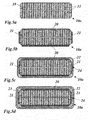
- FIG. 4 shows various steps in the production of a conductor bar according to a second exemplary embodiment of the invention, in a plurality of sub-figures ( FIGS. 4 a - e );
- FIG. 5 shows various steps in the production of a conductor bar according to a third exemplary embodiment of the invention, in a plurality of sub-figures ( FIGS. 5 a - d );
- FIG. 6 shows various steps in the production of a conductor bar according to a fourth exemplary embodiment of the invention, in a plurality of sub-figures ( FIGS. 6 a - d )
- FIG. 3 A detail of the cross section through a conductor bar according to a first exemplary embodiment of the invention is depicted in FIG. 3 .
- a thin layer of a nonwoven 17 is wound as the first layer instead of a glass/mica band 13 .
- This nonwoven 17 may consist of either glass fibers or thermoplastic synthetic fibers (for example PET) or carbon fibers.
- the nonwoven 17 is applied as the lowermost layer onto a glass/mica band with the arrangement nonwoven/mica/glass (from the inside outward).
- Such three-layer bands 16 comprising PET nonwoven are commercially available and are currently used for the manual reinsulation of connection points.
- This first layer with the three-layer band 16 may be wound either over the entire bar or only over the straight part or section of the bar, when there are the greatest dielectric stress and thermomechanical stress due to tangential forces.
- the 1 st layer is wound flush instead of overlapping at least in the straight part (see the flush fit 18 in FIG. 3 ).
- the thickness of the layer is thus reduced (which is favorable for the thermal conduction) and the first layer of mica ( 14 ) is as parallel as possible to the surface of the bar (if the winding overlaps, there will always be positions where the mica orientation also has radial components).
- FIGS. 4 , 5 and 6 depicting various steps in the production of the conductor bar.
- the method according to FIG. 4 is based on a green bar 10 a which has a rectangular cross section and comprises a multiplicity of conductor elements 11 , and whose end faces are filled with conductive cement 19 ( FIG. 4 a ).
- a rectangular cross section is a cross section having an essentially rectangular shape.
- thermosetting silicone elastomer 20 is applied onto the wide sides of the uncompacted green bar 10 a .
- the narrow sides of the green bar 10 a are not coated with the silicone elastomer 20 .
- the narrow sides may be coated with a conductive resin 21 ( FIG. 4 b ).
- the applied layers are represented with an exaggerated thickness in FIG. 4 .
- a conductive band of polyester nonwoven 22 is wound in one layer spirally ( FIG. 4 c ).
- the winding should preferably be carried out flush (i.e. without overlap).
- a layer of a fabric band 23 is then wound over this as a separating and absorber band ( FIG. 4 d ).
- the bar is subsequently compacted in the conventional way in a hot press.
- the conductive polyester nonwoven 22 is thereby also adhesively bonded to the bar; excess silicone elastomer 20 is squeezed out and absorbed by the fabric band 23 .
- the layer of adhesively bonded conductive nonwoven ( 22 ) may extend either over the entire bar or (preferably) only over the straight part (section).
- the conductor bar 10 is insulated and impregnated as usual with glass/mica band 13 (glass fabric 15 upward for all layers) in the conventional way ( FIG. 4 e ).
- Conductive PES nonwovens with a thickness of 0.1 mm are commercially available and are used for the so-called “round packing” of bars. These bands may be used either with their original width (typically 100 mm) or narrower. Also commercially available are thin carbon fiber nonwovens with a thickness of down to 30 ⁇ m.
- the silicone elastomer 20 is pressed to zero thickness on the end faces of the conductor elements 11 .
- the connection between the bar and the conductive nonwoven ( 22 ) is provided by the silicone elastomer 20 remaining in the gaps between the conductor elements 11 .
- the effect achieved by this is that the additional thickness is reduced merely to the thickness of the conductive nonwoven ( 22 ), i.e. for example 0.1 mm.
- the silicone elastomer 20 is capable of absorbing mechanical stresses without tearing. This achieves improved connection of the insulation to the bar and reduces the risk of cavitation. If separation from the bar nevertheless take place in the silicone elastomer layer, there is still the advantage that this cavity will have a floating potential and be therefore free from partial discharges.
- FIG. 5 A variant of the method shown in FIG. 4 is represented in FIG. 5 , parts which are the same being provided with the same references.
- the method according to FIG. 5 is carried out similarly as that in FIG. 4 , except that large webs of conductive nonwoven are wound around the straight part of the bar, instead of a spirally wound band of conductive polyester nonwoven 22 .
- the length of the web corresponds to the length of the straight part (section) of the bar, and the width of the web corresponds to the bar circumference or (preferably) is somewhat smaller.
- FIGS. 5 c and 5 d This creates a narrow gap 24 in the axial direction ( FIGS. 5 c and 5 d ), through which the excess resin 21 can escape.
- the web is preferably wound so that the gap lies on one of the two narrow sides, as indicated in FIGS. 5 c and 5 d .
- n webs instead of a single web with the full length L of the straight part, it is also possible to use n webs with a length of L/n.
- the other steps in this method are the same as in FIG. 4 .
- the representation of the final winding process with the glass/mica band 13 corresponding to FIG. 4 e , has been omitted to save space.
- FIG. 6 Another variant of the method shown in FIG. 4 is represented in FIG. 6 , parts which are the same again being provided with the same references.
- the green bar 10 a may be uncompacted or already compacted. Adhesive bonding between the conductive nonwoven 22 and the green bar 10 a is carried out only via the narrow sides (again with conductive resin 21 ).
- the wide sides of the green bar 10 a either remain dry or are even treated with a separator 25 (for example PTFE spray, or paste).
- a separator 25 for example PTFE spray, or paste.
- the winding with the conductive nonwoven 22 is carried out as in FIG. 4 or 5 . This reliably ensures that any cavity being formed will have a floating potential.
- the other steps are also carried out similarly as FIG. 4 or 5 .
- this variant has the advantage that it is much less thick (only an increase of 0.1-0.2 mm in the total insulation thickness).
Landscapes
- Engineering & Computer Science (AREA)
- Power Engineering (AREA)
- Insulating Bodies (AREA)
- Insulation, Fastening Of Motor, Generator Windings (AREA)
- Manufacture Of Motors, Generators (AREA)
Abstract
A conductor bar for a stator of a generator includes a plurality of internal conductor elements; an insulation wound around the plurality of internal conductor elements so as to externally enclose the plurality of internal conductor elements, the insulation including impregnated glass/mica bands; and at least one interlayer disposed between the insulation and the plurality of internal conductor elements so as to improve a mechanical connection between the plurality of internal conductor elements and the insulation.
Description
This application is a continuation of International Patent Application No. PCT/EP2008/050249, filed on Jan. 10, 2008, which claims priority to Swiss Patent Application No. CH 00067/07, filed on Jan. 18, 2007. The entire disclosure of both applications is incorporated by reference herein.
The present invention concerns the field of rotating electrical machines. It relates to a conductor bar for the stator of a generator, and to a method for producing such a conductor bar.
Known conductor bars in the stators of generators have in cross section an internal structure as depicted in FIG. 1 (see also Document DE 19817287). A conductor bar 10 contains a multiplicity of conductor elements 11, which are enclosed by insulation 12. The insulation consists of glass/mica bands, which are wound around and impregnated by a so-called vacuum-pressure method (see also H Sequenz: “Herstellung von Wicklungen electrischer Maschinen” [production of windings of electrical machines] Springer Verlag 1973, pp. 150-154). In the glass/mica bands (13 in FIG. 2 ), the mica is provided as so-called mica paper 14 which is applied onto a glass filament fabric or glass fabric 15 in order to improve the mechanical strength. Mica is a mineral which belongs to the group of sheet silicates. This sheet-like atomic structure causes mica crystals to have macroscopic shapes which are also very much like platelets.
The mica paper 14 consists of a multiplicity of platelets stacked on and above one another, all of which essentially lie in a plane. The glass/mica bands 13 are wound axially onto the conductor bar in a plurality of layers so that they overlap. Since the electric field is predominantly radial with respect to the bar axis, the platelets are oriented perpendicularly to the field direction. Mica platelets have a very high dielectric strength in this direction, which is then imparted to the insulation as a whole owing to the parallel alignment of the platelets.
That which promotes the dielectric strength, however, is detrimental to the mechanical strength—especially the thermal and mechanical strength: the insulation has a different thermal expansion coefficient to the Cu bar, with the conductor elements 11, which it encloses, so that thermal stresses between the Cu and the insulation 12 are unavoidably formed during thermal cycles. These are greatest in or in the vicinity of the boundary layer. If the band is then wound so that the mica side faces toward the band (which would be favorable in terms of winding technology and for electrical reasons), this can easily lead to mechanical shearing with the first mica layer usually remaining attached to the Cu.
The shearing produces sizeable cavities, which are detrimental for two reasons:
-
- they reduce the thermal conduction radially with respect to the bar direction;
- undesired partial discharges are ignited in them.
As a simple countermeasure to suppress the cavities, the first layer is often wound with the glass facing downward, and the second and subsequent layers with the mica facing downward.
In this case, however, two problems arise:
-
- when winding “with the mica outward”, the
mica paper 14 is bent sharply over the edges and usually breaks. At least some of the mica platelets therefore lose their alignment, which weakens the dielectric strength. - Between the 1st and 2nd layers, 2 mica layers lie directly on one another, and it is often observed that the insulation then tears between the 1st and 2nd layers, or in the mica of the 1st layer, instead of near the interface between the Cu and the 1st layer.
- when winding “with the mica outward”, the
A very different approach employs the following measure:
-
- a layer of mica paper is initially wound on the (uncured) green bar with the mica side toward the bar.
- A layer of conductive band is wound over this, and is electrically connected to the green bar in the vicinity of the lug holes. Only then is the main insulation applied with the desired thickness. If disbanding now takes place, this will be very likely to occur in the first mica layer directly on the bar. Since this cavity has a floating potential, owing to the conductor band lying above it, partial discharges are prevented.
This measure, however, does not help to prevent degradation of the thermal conduction. Added to this, another disadvantage is that the additional layer of mica and the conductor band increase the total thickness of the insulation (0.3-0.5 mm on each side).
An aspect of the invention is to provide a conductor bar in which the mechanical connection between the bar and the insulation is improved, the dielectric strength being preserved or even improved, and to present a method for its production.
An aspect of the invention is that, in order to improve the mechanical connection between the conductor elements and the insulation, at least one interlayer is provided between the insulation and the conductor elements.
One configuration of the invention is characterized in that the interlayer comprises a nonwoven, which preferably consists of glass fibers or thermoplastic synthetic fibers, in particular made of PET, or of carbon fibers, or a mixed nonwoven thereof, in particular carbon fibers and thermoplastic synthetic fibers or carbon and glass fibers.
The nonwoven may in particular be applied onto a glass/mica band and thus be part of a three-layer band, which at the same time forms the first layer of the insulation.
If the conductor bar has a straight section, the three-layer band will be wound around the conductor elements at least in the straight section, the three-layer band preferably being wound flush in the straight section of the conductor bar.
Another configuration of the invention is distinguished in that the interlayer consists of a layer sequence of conductive polyester nonwoven and a fabric band placed thereon.
If the conductor bar has a straight section, a band of conductive polyester nonwoven will be wound around the conductor elements at least in the straight section.
The polyester nonwoven will in particular be wound in one layer spirally, and preferably flush, around the conductor elements.
It is, however, also conceivable for a web of conductive polyester nonwoven to be wound flush around the conductor elements with the longitudinal axis parallel to the longitudinal axis of the conductor bar, so as to create a gap extending in the axial direction between the adjacent longitudinal edges of the web.
Preferably, the conductor bar has an essentially rectangular cross section with narrow sides and wide sides and the conductive polyester nonwoven is adhesively bonded to the conductor elements on the narrow sides by means of a conductive resin.
The conductive polyester nonwoven may furthermore be adhesively bonded to the conductor elements by means of a thermosetting silicone elastomer on the wide sides of the conductor bar.
It is, however, also conceivable for the conductive polyester nonwoven to be separated from the conductor elements by a separator on the wide sides of the conductor bar.
One configuration of the method according to the invention is characterized in that a nonwoven is applied as the interlayer, and in that a three-layer band containing the nonwoven is wound around the green bar in order to apply the nonwoven.
Another possibility consists in initially winding a band or a web of conductive polyester nonwoven around the green bar in order to form the interlayer, and in winding a layer of a separating and absorbing fabric band over the nonwoven.
If the conductor bar has an essentially rectangular cross section with narrow sides and wide sides, then the green bar will preferably be coated with a conductive resin on the narrow sides before the nonwoven is applied, in order to bind the nonwoven.
A thermosetting silicone elastomer may furthermore be applied onto the wide sides of the green bar before the nonwoven is applied, or a separator is applied onto the wide sides of the green bar before the nonwoven is applied.
The invention will be explained in more detail below with the aid of exemplary embodiments in conjunction with the drawing, in which:
A detail of the cross section through a conductor bar according to a first exemplary embodiment of the invention is depicted in FIG. 3 . On the conductor bar 10 of FIG. 3 , a thin layer of a nonwoven 17 is wound as the first layer instead of a glass/mica band 13. This nonwoven 17 may consist of either glass fibers or thermoplastic synthetic fibers (for example PET) or carbon fibers. In a preferred embodiment, the nonwoven 17 is applied as the lowermost layer onto a glass/mica band with the arrangement nonwoven/mica/glass (from the inside outward). Such three-layer bands 16 comprising PET nonwoven are commercially available and are currently used for the manual reinsulation of connection points.
The use of such three-layer bands 16 comprising PET nonwoven is known from the so-called “resin-rich” technique. In this case, the entire conductor bar is wound with triple bands. Disadvantages are on the one hand that the PET nonwoven layer has poor thermal conduction, and on the other hand the total proportion of mica in the insulation is reduced, which is unfavorable for the dielectric strength.
In the configuration according to FIG. 3 , only the first layer is applied with a three-layer band 16; winding is then carried out using a conventional glass/mica band 13 with the glass fabric 15 placed outward—as is customary. The insulation is compressed before or after the impregnation. The nonwoven 17 is thereby partially pressed into the gaps between the conductor elements 11 (see FIG. 3 ). After the bar has been cured, this structure forms an effective force fit between the bar and the insulation. Furthermore, thermoplastics have a very good extensibility so that the structure (especially at elevated temperatures) can naturally absorb any thermomechanical stresses still existing. A comparable effect is also achieved by carbon fiber nonwoven or carbon fiber/PET mixed nonwoven.
This first layer with the three-layer band 16 may be wound either over the entire bar or only over the straight part or section of the bar, when there are the greatest dielectric stress and thermomechanical stress due to tangential forces.
In a preferred embodiment, the 1st layer is wound flush instead of overlapping at least in the straight part (see the flush fit 18 in FIG. 3 ). The thickness of the layer is thus reduced (which is favorable for the thermal conduction) and the first layer of mica (14) is as parallel as possible to the surface of the bar (if the winding overlaps, there will always be positions where the mica orientation also has radial components).
Other configurations of the invention may be explained with the aid of FIGS. 4 , 5 and 6, each of these figures depicting various steps in the production of the conductor bar.
The method according to FIG. 4 is based on a green bar 10 a which has a rectangular cross section and comprises a multiplicity of conductor elements 11, and whose end faces are filled with conductive cement 19 (FIG. 4 a). As recited herein, a rectangular cross section is a cross section having an essentially rectangular shape.
A thermosetting silicone elastomer 20 is applied onto the wide sides of the uncompacted green bar 10 a. The narrow sides of the green bar 10 a are not coated with the silicone elastomer 20. In order to ensure one hundred percent binding of the conductive nonwoven with which it is subsequently wound, the narrow sides may be coated with a conductive resin 21 (FIG. 4 b). For the sake of clarity, the applied layers are represented with an exaggerated thickness in FIG. 4 .
Over the green bar 10 a prepared in this way, a conductive band of polyester nonwoven 22 is wound in one layer spirally (FIG. 4 c). The winding should preferably be carried out flush (i.e. without overlap).
A layer of a fabric band 23 is then wound over this as a separating and absorber band (FIG. 4 d). The bar is subsequently compacted in the conventional way in a hot press. The conductive polyester nonwoven 22 is thereby also adhesively bonded to the bar; excess silicone elastomer 20 is squeezed out and absorbed by the fabric band 23. The layer of adhesively bonded conductive nonwoven (22) may extend either over the entire bar or (preferably) only over the straight part (section).
After compaction, the conductor bar 10 is insulated and impregnated as usual with glass/mica band 13 (glass fabric 15 upward for all layers) in the conventional way (FIG. 4 e).
Conductive PES nonwovens with a thickness of 0.1 mm are commercially available and are used for the so-called “round packing” of bars. These bands may be used either with their original width (typically 100 mm) or narrower. Also commercially available are thin carbon fiber nonwovens with a thickness of down to 30 μm. By the pressing process, the silicone elastomer 20 is pressed to zero thickness on the end faces of the conductor elements 11. The connection between the bar and the conductive nonwoven (22) is provided by the silicone elastomer 20 remaining in the gaps between the conductor elements 11. The effect achieved by this is that the additional thickness is reduced merely to the thickness of the conductive nonwoven (22), i.e. for example 0.1 mm. In contrast to adhesive bonding with epoxy, the silicone elastomer 20 is capable of absorbing mechanical stresses without tearing. This achieves improved connection of the insulation to the bar and reduces the risk of cavitation. If separation from the bar nevertheless take place in the silicone elastomer layer, there is still the advantage that this cavity will have a floating potential and be therefore free from partial discharges.
A variant of the method shown in FIG. 4 is represented in FIG. 5 , parts which are the same being provided with the same references. The method according to FIG. 5 is carried out similarly as that in FIG. 4 , except that large webs of conductive nonwoven are wound around the straight part of the bar, instead of a spirally wound band of conductive polyester nonwoven 22. The length of the web corresponds to the length of the straight part (section) of the bar, and the width of the web corresponds to the bar circumference or (preferably) is somewhat smaller.
This creates a narrow gap 24 in the axial direction (FIGS. 5 c and 5 d), through which the excess resin 21 can escape. The web is preferably wound so that the gap lies on one of the two narrow sides, as indicated in FIGS. 5 c and 5 d. Instead of a single web with the full length L of the straight part, it is also possible to use n webs with a length of L/n. The other steps in this method are the same as in FIG. 4 . The representation of the final winding process with the glass/mica band 13, corresponding to FIG. 4 e, has been omitted to save space.
Another variant of the method shown in FIG. 4 is represented in FIG. 6 , parts which are the same again being provided with the same references. For this variant, the green bar 10 a may be uncompacted or already compacted. Adhesive bonding between the conductive nonwoven 22 and the green bar 10 a is carried out only via the narrow sides (again with conductive resin 21).
The wide sides of the green bar 10 a either remain dry or are even treated with a separator 25 (for example PTFE spray, or paste). The winding with the conductive nonwoven 22 is carried out as in FIG. 4 or 5. This reliably ensures that any cavity being formed will have a floating potential. The other steps are also carried out similarly as FIG. 4 or 5. In contrast to the prior art, in which the first layer of glass/mica band acts as a sacrificial break point, this variant has the advantage that it is much less thick (only an increase of 0.1-0.2 mm in the total insulation thickness).
- 10 conductor bar
- 10 a green bar
- 11 conductor elements
- 12 insulation
- 13 glass/mica band
- 14 mica paper
- 15 glass fabric
- 16 three-layer band
- 17 nonwoven
- 18 flush fit
- 19 cement
- 20 silicone elastomer
- 21 conductive resin
- 22 polyester nonwoven (conductive)
- 23 fabric band
- 24 gap (axial)
- 25 separator
Claims (19)
1. A conductor bar for a stator of a generator comprising:
a plurality of internal conductor elements;
an insulation wound around the plurality of internal conductor elements so as to externally enclose the plurality of internal conductor elements, the insulation including impregnated glass/mica bands; and
at least one interlayer disposed between the insulation and the plurality of internal conductor elements so as to improve a mechanical connection between the plurality of internal conductor elements and the insulation, wherein the interlayer includes a layer sequence of conductive polyester nonwoven and a fabric band, and wherein the conductor bar includes a rectangular cross section having at least one narrow side and at least one wide side and wherein a conductive resin adhesively bonds the conductive polyester nonwoven to the plurality of internal conductor elements on the at least one narrow side.
2. The conductor bar as recited in claim 1 , wherein the at least one interlayer includes a nonwoven.
3. The conductor bar as recited in claim 2 , wherein the nonwoven includes glass fibers.
4. The conductor bar as recited in claim 2 , wherein the nonwoven includes thermoplastic synthetic fibers.
5. The conductor bar as recited in claim 2 , wherein the nonwoven includes carbon fibers.
6. The conductor bar as recited in claim 2 , wherein the nonwoven includes a fabric having fibers made of at least two different materials.
7. The conductor bar as recited in claim 2 , wherein the nonwoven is disposed on the glass/mica band so as to form a three-layer band as a first insulation layer.
8. The conductor bar as recited in claim 7 , wherein the conductor bar has a straight section and the three-layer band wound around the plurality of conductor elements at least in the straight section.
9. The conductor bar as recited in claim 8 , wherein the three-layer band is wound flush in the straight section of the conductor bar.
10. The conductor bar as recited in claim 1 , wherein the conductor bar has a straight section and a band of conductive polyester nonwoven wound around the plurality of internal conductor elements at least in the straight section.
11. The conductor bar as recited in claim 10 , wherein the band of conductive polyester nonwoven is spirally wound in one layer around the plurality of internal conductor elements.
12. The conductor bar as recited in claim 10 , wherein the band of conductive polyester nonwoven is wound flush around the plurality of conductor elements so as to define a first longitudinal axis parallel to a second longitudinal axis of the conductor bar and forms a gap extending in an axial direction between the adjacent longitudinal edges of the band.
13. The conductor bar as recited in claim 1 , wherein a thermosetting silicone elastomer adhesively bonds the conductive polyester nonwoven to the plurality of internal conductor elements on the at least one wide side.
14. The conductor bar as recited in claim 1 , further comprising a separator disposed on the at least one wide side and separating the conductive polyester nonwoven from the plurality of internal conductor elements.
15. A method for producing a conductor bar comprising:
applying at least one interlayer onto a green bar, the green bar including a plurality of internal conductor elements, wherein the applying includes winding one of a band and a web of conductive polyester nonwoven around the green bar and winding a layer of separating and absorbing fabric band over the polyester nonwoven;
winding a glass/mica band around the green bar so as to form an arrangement;
impregnating and curing the arrangement, wherein the conductor bar includes a rectangular cross section having at least one narrow side and at least one wide side; and
coating the green bar on the at least one narrow side before the winding of the polyester nonwoven step so as to bind the polyester nonwoven.
16. The method as recited in claim 15 , wherein the at least one interlayer includes a nonwoven, and the applying the nonwoven includes winding a three-layer band containing the nonwoven around the green bar.
17. The method as recited in claim 15 , further comprising applying a thermosetting silicone elastomer onto the at least one wide side before the winding of the polyester nonwoven step.
18. The method as recited in claim 15 , further comprising applying a separator onto the at least one wide side before the winding of the polyester nonwoven step.
19. A conductor bar for a stator of a generator comprising:
a plurality of internal conductor elements, wherein the conductor bar has a straight section and a band of conductive polyester nonwoven wound around the plurality of internal conductor elements at least in the straight section;
an insulation wound around the plurality of internal conductor elements so as to externally enclose the plurality of internal conductor elements, the insulation including impregnated glass/mica bands; and
at least one interlayer disposed between the insulation and the plurality of internal conductor elements so as to improve a mechanical connection between the plurality of internal conductor elements and the insulation, wherein the interlayer includes a layer sequence of conductive polyester nonwoven and a fabric band, and wherein the band of conductive polyester nonwoven is wound flush around the plurality of conductor elements so as to define a first longitudinal axis parallel to a second longitudinal axis of the conductor bar and forms a gap extending in an axial direction between the adjacent longitudinal edges of the band.
Priority Applications (1)
| Application Number | Priority Date | Filing Date | Title |
|---|---|---|---|
| US13/006,502 US20110109186A1 (en) | 2007-01-18 | 2011-01-14 | Conductor bar for the stator of a generator and method for its production |
Applications Claiming Priority (3)
| Application Number | Priority Date | Filing Date | Title |
|---|---|---|---|
| CH00067/07A CH699023B1 (en) | 2007-01-18 | 2007-01-18 | Conductor bar for the stator of a generator as well as methods for its production. |
| CH00067/07 | 2007-01-18 | ||
| PCT/EP2008/050249 WO2008087093A1 (en) | 2007-01-18 | 2008-01-10 | Conductor rod for the stator of a generator, and method for the production thereof |
Related Parent Applications (1)
| Application Number | Title | Priority Date | Filing Date |
|---|---|---|---|
| PCT/EP2008/050249 Continuation WO2008087093A1 (en) | 2007-01-18 | 2008-01-10 | Conductor rod for the stator of a generator, and method for the production thereof |
Related Child Applications (1)
| Application Number | Title | Priority Date | Filing Date |
|---|---|---|---|
| US13/006,502 Continuation US20110109186A1 (en) | 2007-01-18 | 2011-01-14 | Conductor bar for the stator of a generator and method for its production |
Publications (2)
| Publication Number | Publication Date |
|---|---|
| US20100007226A1 US20100007226A1 (en) | 2010-01-14 |
| US7893358B2 true US7893358B2 (en) | 2011-02-22 |
Family
ID=37951741
Family Applications (2)
| Application Number | Title | Priority Date | Filing Date |
|---|---|---|---|
| US12/502,350 Expired - Fee Related US7893358B2 (en) | 2007-01-18 | 2009-07-14 | Conductor bar for the stator of a generator, and method for its production |
| US13/006,502 Abandoned US20110109186A1 (en) | 2007-01-18 | 2011-01-14 | Conductor bar for the stator of a generator and method for its production |
Family Applications After (1)
| Application Number | Title | Priority Date | Filing Date |
|---|---|---|---|
| US13/006,502 Abandoned US20110109186A1 (en) | 2007-01-18 | 2011-01-14 | Conductor bar for the stator of a generator and method for its production |
Country Status (7)
| Country | Link |
|---|---|
| US (2) | US7893358B2 (en) |
| EP (1) | EP2102968A1 (en) |
| JP (1) | JP2010517497A (en) |
| CN (1) | CN101584101A (en) |
| CA (1) | CA2675821A1 (en) |
| CH (1) | CH699023B1 (en) |
| WO (1) | WO2008087093A1 (en) |
Cited By (3)
| Publication number | Priority date | Publication date | Assignee | Title |
|---|---|---|---|---|
| US8097996B1 (en) | 2011-06-24 | 2012-01-17 | Dantam K Rao | Thermally conductive ground wall insulation for a stator bar |
| US9059616B1 (en) * | 2014-08-20 | 2015-06-16 | Dantam K. Rao | Insulation system for a stator bar with low partial discharge |
| EP4422037A1 (en) * | 2023-02-22 | 2024-08-28 | Siemens Gamesa Renewable Energy Innovation & Technology S.L. | Stator winding arrangement for a wind turbine generator, wind turbine generator, wind turbine and method for manufacturing a stator winding arrangement |
Families Citing this family (12)
| Publication number | Priority date | Publication date | Assignee | Title |
|---|---|---|---|---|
| DE102008000073A1 (en) * | 2008-01-17 | 2009-07-23 | Alstom Technology Ltd. | Ladder for a rotating electrical machine |
| US8278795B2 (en) * | 2009-09-18 | 2012-10-02 | Siemens Energy, Inc. | Voltage grading structure in a high-voltage stator coil of an electromotive machine |
| EP2403112A1 (en) * | 2010-07-02 | 2012-01-04 | Alstom Technology Ltd | Stator bar |
| CN102296424A (en) * | 2011-08-22 | 2011-12-28 | 海宁永大电气新材料有限公司 | Anticorona low-resistance belt and manufacture method thereof |
| US8866361B2 (en) * | 2011-10-17 | 2014-10-21 | GM Global Technology Operations LLC | Bar conductor shapes for electric machines |
| US20130093280A1 (en) * | 2011-10-17 | 2013-04-18 | GM Global Technology Operations LLC | Multi-filar bar conductors for electric machines |
| EP2645373A1 (en) * | 2012-03-26 | 2013-10-02 | Siemens Aktiengesellschaft | Material for isolation system, isolation system, outer corona protection and an electric machine |
| EP2869435A1 (en) * | 2013-11-05 | 2015-05-06 | Siemens Aktiengesellschaft | Insulation assembly, electrical equipment and electric machine with extended service life |
| JP6635935B2 (en) * | 2014-03-20 | 2020-01-29 | ゼネラル エレクトリック テクノロジー ゲゼルシャフト ミット ベシュレンクテル ハフツングGeneral Electric Technology GmbH | Insulating material and manufacturing method |
| EP3269540A1 (en) * | 2016-07-15 | 2018-01-17 | Von Roll Schweiz AG | Compressible and flexible composite material useful in particular as a construction material for batteries |
| EP3503354A1 (en) * | 2017-12-20 | 2019-06-26 | Siemens Aktiengesellschaft | Isolation of sub-conductors of a dynamoelectric machine |
| EP3793068A1 (en) * | 2019-09-12 | 2021-03-17 | GE Renewable Technologies | Conductor bar |
Citations (14)
| Publication number | Priority date | Publication date | Assignee | Title |
|---|---|---|---|---|
| DE2004228A1 (en) | 1970-01-30 | 1971-08-05 | Licentia Gmbh | Method and device for impregnating a web-like or band-shaped porous carrier body with a resin lacquer dispersion containing electrically conductive particles |
| DE2320828A1 (en) | 1973-04-25 | 1974-11-14 | Schorch Gmbh | SLOT PROTECTION FOR HIGH VOLTAGE WINDINGS OF ELECTRIC MACHINERY |
| US4865905A (en) * | 1983-06-23 | 1989-09-12 | Raychem Corporation | Article for protection of a substrate |
| US5540969A (en) * | 1992-12-28 | 1996-07-30 | Asea Brown Boveri Ltd. | Insulating tape and method of producing it |
| DE19536209A1 (en) | 1995-09-28 | 1996-12-12 | Siemens Ag | Combination band for insulating and glow protection of electrical conductor rods and conductor rod for generator |
| WO1997027661A1 (en) | 1996-01-25 | 1997-07-31 | ISOVOLTA Österreichische Isolierstoffwerke Aktiengesellschaft | Process for producing a high-voltage insulating system for electrical machines |
| US5723920A (en) * | 1994-10-12 | 1998-03-03 | General Electric Company | Stator bars internally graded with conductive binder tape |
| DE19817287A1 (en) | 1998-04-18 | 1999-10-21 | Abb Research Ltd | Winding rod for the high-voltage winding of an electrical machine and method for producing such a winding rod |
| US6043582A (en) * | 1998-08-19 | 2000-03-28 | General Electric Co. | Stable conductive material for high voltage armature bars |
| DE19860412A1 (en) | 1998-12-28 | 2000-06-29 | Abb Research Ltd | Manufacturing of motor coils involves winding oval coils, applying internal discharge protective impregnated tape, spreading coils, and applying insulation and outer discharge protection |
| US6140590A (en) * | 1997-05-16 | 2000-10-31 | Abb Research Ltd. | Stator winding insulation |
| US6288341B1 (en) | 1998-02-27 | 2001-09-11 | Hitachi, Ltd. | Insulating material windings using same and a manufacturing method thereof |
| EP1154542A1 (en) | 2000-05-12 | 2001-11-14 | ALSTOM Power N.V. | Coil insulating method |
| GB2406721A (en) | 2003-10-02 | 2005-04-06 | Gen Electric | Extruded insulation secured arround a stator bar |
-
2007
- 2007-01-18 CH CH00067/07A patent/CH699023B1/en not_active IP Right Cessation
-
2008
- 2008-01-10 WO PCT/EP2008/050249 patent/WO2008087093A1/en active Application Filing
- 2008-01-10 CA CA002675821A patent/CA2675821A1/en not_active Abandoned
- 2008-01-10 JP JP2009545892A patent/JP2010517497A/en not_active Withdrawn
- 2008-01-10 CN CN200880002522.8A patent/CN101584101A/en active Pending
- 2008-01-10 EP EP08701395A patent/EP2102968A1/en not_active Withdrawn
-
2009
- 2009-07-14 US US12/502,350 patent/US7893358B2/en not_active Expired - Fee Related
-
2011
- 2011-01-14 US US13/006,502 patent/US20110109186A1/en not_active Abandoned
Patent Citations (17)
| Publication number | Priority date | Publication date | Assignee | Title |
|---|---|---|---|---|
| DE2004228A1 (en) | 1970-01-30 | 1971-08-05 | Licentia Gmbh | Method and device for impregnating a web-like or band-shaped porous carrier body with a resin lacquer dispersion containing electrically conductive particles |
| DE2320828A1 (en) | 1973-04-25 | 1974-11-14 | Schorch Gmbh | SLOT PROTECTION FOR HIGH VOLTAGE WINDINGS OF ELECTRIC MACHINERY |
| US4865905A (en) * | 1983-06-23 | 1989-09-12 | Raychem Corporation | Article for protection of a substrate |
| US5540969A (en) * | 1992-12-28 | 1996-07-30 | Asea Brown Boveri Ltd. | Insulating tape and method of producing it |
| US5723920A (en) * | 1994-10-12 | 1998-03-03 | General Electric Company | Stator bars internally graded with conductive binder tape |
| DE19536209A1 (en) | 1995-09-28 | 1996-12-12 | Siemens Ag | Combination band for insulating and glow protection of electrical conductor rods and conductor rod for generator |
| WO1997027661A1 (en) | 1996-01-25 | 1997-07-31 | ISOVOLTA Österreichische Isolierstoffwerke Aktiengesellschaft | Process for producing a high-voltage insulating system for electrical machines |
| US6140590A (en) * | 1997-05-16 | 2000-10-31 | Abb Research Ltd. | Stator winding insulation |
| US6504102B2 (en) * | 1998-02-27 | 2003-01-07 | Hitachi, Ltd. | Insulating material, windings using same, and a manufacturing method thereof |
| US6288341B1 (en) | 1998-02-27 | 2001-09-11 | Hitachi, Ltd. | Insulating material windings using same and a manufacturing method thereof |
| US6404092B1 (en) | 1998-04-18 | 2002-06-11 | Abb Research Ltd. | Winding bar for the high-voltage winding of an electric machine, and a method for producing such a winding bar |
| DE19817287A1 (en) | 1998-04-18 | 1999-10-21 | Abb Research Ltd | Winding rod for the high-voltage winding of an electrical machine and method for producing such a winding rod |
| US6043582A (en) * | 1998-08-19 | 2000-03-28 | General Electric Co. | Stable conductive material for high voltage armature bars |
| DE19860412A1 (en) | 1998-12-28 | 2000-06-29 | Abb Research Ltd | Manufacturing of motor coils involves winding oval coils, applying internal discharge protective impregnated tape, spreading coils, and applying insulation and outer discharge protection |
| US20010045687A1 (en) | 2000-05-12 | 2001-11-29 | Thomas Baumann | Insulation of coils |
| EP1154542A1 (en) | 2000-05-12 | 2001-11-14 | ALSTOM Power N.V. | Coil insulating method |
| GB2406721A (en) | 2003-10-02 | 2005-04-06 | Gen Electric | Extruded insulation secured arround a stator bar |
Non-Patent Citations (1)
| Title |
|---|
| Sequenz, Herstellung von Wicklungen electrischer Maschinen [production of windings of electrical machines] Springer Verlag 1973, pp. 150-154. |
Cited By (4)
| Publication number | Priority date | Publication date | Assignee | Title |
|---|---|---|---|---|
| US8097996B1 (en) | 2011-06-24 | 2012-01-17 | Dantam K Rao | Thermally conductive ground wall insulation for a stator bar |
| US9059616B1 (en) * | 2014-08-20 | 2015-06-16 | Dantam K. Rao | Insulation system for a stator bar with low partial discharge |
| EP4422037A1 (en) * | 2023-02-22 | 2024-08-28 | Siemens Gamesa Renewable Energy Innovation & Technology S.L. | Stator winding arrangement for a wind turbine generator, wind turbine generator, wind turbine and method for manufacturing a stator winding arrangement |
| WO2024175263A1 (en) * | 2023-02-22 | 2024-08-29 | Siemens Gamesa Renewable Energy Innovation & Technology S.L. | Stator winding arrangement for a wind turbine generator, wind turbine generator, wind turbine and method for manufacturing a stator winding arrangement |
Also Published As
| Publication number | Publication date |
|---|---|
| CH699023B1 (en) | 2010-01-15 |
| US20110109186A1 (en) | 2011-05-12 |
| CA2675821A1 (en) | 2008-07-24 |
| US20100007226A1 (en) | 2010-01-14 |
| WO2008087093A1 (en) | 2008-07-24 |
| CN101584101A (en) | 2009-11-18 |
| EP2102968A1 (en) | 2009-09-23 |
| JP2010517497A (en) | 2010-05-20 |
Similar Documents
| Publication | Publication Date | Title |
|---|---|---|
| US7893358B2 (en) | Conductor bar for the stator of a generator, and method for its production | |
| US7893357B2 (en) | Roebel winding with conductive felt | |
| CN105324919B (en) | Method for manufacturing electric power rotary machine and electric power rotary machine | |
| US9590460B2 (en) | Electric machine with a slot liner | |
| KR101464628B1 (en) | Wrapped stator coil | |
| US4038741A (en) | Method of making electrical coils for dynamo-electric machines having band-formed insulation material | |
| JP2007174816A (en) | Stator of rotating electric machine and its manufacturing method | |
| US20140083592A1 (en) | Method of producing an electrical insulation system for an electric machine | |
| JP2000510317A (en) | Method for producing support for electric winding and structure for preventing corona | |
| JP2007282410A (en) | Rotating electric machine, stator coil thereof, its manufacturing method, and semiconductive sheet, semiconductive tape | |
| CN102185432B (en) | Method for realizing insulation around a conductive bar | |
| EP1267472B1 (en) | Electrical isolation layer for generator stator strand assembly and other uses | |
| US20090045692A1 (en) | Capped stator core wedge and related method | |
| KR101918436B1 (en) | Inorganic electrical insulation material | |
| JP2009240131A (en) | Stator coil of rotary electric machine and method of manufacturing the same | |
| US20100109469A1 (en) | Capped stator core wedge and related method | |
| US2581862A (en) | Insulation | |
| US5973269A (en) | Multi-layer insulation for winding elements of dynamoelectric machines (D.E.M.s) | |
| JP5454709B2 (en) | Method for manufacturing stator coil of rotating electric machine | |
| US9711264B2 (en) | Winding layers composed of different materials | |
| JPH09149578A (en) | High pressure rotating machine coil | |
| JP2005027456A (en) | Rotating electric machine | |
| JPS6055846A (en) | Forming method of salient-pole field pole | |
| JPH06225489A (en) | Stator coil of high voltage rotary apparatus | |
| JPS59153447A (en) | Manufacture of coil for rotary electric machine |
Legal Events
| Date | Code | Title | Description |
|---|---|---|---|
| AS | Assignment |
Owner name: ALSTOM TECHNOLOGY LTD, SWITZERLAND Free format text: ASSIGNMENT OF ASSIGNORS INTEREST;ASSIGNOR:BAUMANN, THOMAS;REEL/FRAME:023283/0176 Effective date: 20090918 |
|
| REMI | Maintenance fee reminder mailed | ||
| LAPS | Lapse for failure to pay maintenance fees | ||
| STCH | Information on status: patent discontinuation |
Free format text: PATENT EXPIRED DUE TO NONPAYMENT OF MAINTENANCE FEES UNDER 37 CFR 1.362 |
|
| FP | Lapsed due to failure to pay maintenance fee |
Effective date: 20150222 |