US7892711B2 - Azo compound, composition for photo-alignment film using the same, and method for producing photo-alignment film - Google Patents
Azo compound, composition for photo-alignment film using the same, and method for producing photo-alignment film Download PDFInfo
- Publication number
- US7892711B2 US7892711B2 US11/629,984 US62998405A US7892711B2 US 7892711 B2 US7892711 B2 US 7892711B2 US 62998405 A US62998405 A US 62998405A US 7892711 B2 US7892711 B2 US 7892711B2
- Authority
- US
- United States
- Prior art keywords
- group
- general formula
- photo
- alignment film
- represented
- Prior art date
- Legal status (The legal status is an assumption and is not a legal conclusion. Google has not performed a legal analysis and makes no representation as to the accuracy of the status listed.)
- Active, expires
Links
- 0 [1*]CC1=CC=C(N=NC2=CC=C(C)C=C2)C=C1.[2*]CC1=CC=C(N=NC2=CC=C(C)C=C2)C=C1.[3*]C.[4*]C.[5*]C.[6*]C Chemical compound [1*]CC1=CC=C(N=NC2=CC=C(C)C=C2)C=C1.[2*]CC1=CC=C(N=NC2=CC=C(C)C=C2)C=C1.[3*]C.[4*]C.[5*]C.[6*]C 0.000 description 15
- PAXVARXORSXKSK-UHFFFAOYSA-L C=CC(=O)OCCCCCCOC1=CC=C(C(=O)OC2=CC=C(N=NC3=CC=C(C4=CC=C(N=NC5=CC(C(=O)O)=C(OC(=O)C6=CC=C(OCCCCCCOC(=O)C=C)C=C6)C=C5)C=C4S(=O)(=O)O[Na])C(SOOO[Na])=C3)C=C2C(=O)O)C=C1 Chemical compound C=CC(=O)OCCCCCCOC1=CC=C(C(=O)OC2=CC=C(N=NC3=CC=C(C4=CC=C(N=NC5=CC(C(=O)O)=C(OC(=O)C6=CC=C(OCCCCCCOC(=O)C=C)C=C6)C=C5)C=C4S(=O)(=O)O[Na])C(SOOO[Na])=C3)C=C2C(=O)O)C=C1 PAXVARXORSXKSK-UHFFFAOYSA-L 0.000 description 1
- ODZAXYUWAPTKSI-UHFFFAOYSA-H C=CC(=O)OCCCCCCOC1=CC=C(C(=O)OC2=CC=C(N=NC3=CC=C(C4=CC=C(N=NC5=CC(C(=O)O)=C(OC(=O)C6=CC=C(OCCCCCCOC(=O)C=C)C=C6)C=C5)C=C4S(=O)(=O)O[Na])C(SOOO[Na])=C3)C=C2C(=O)O)C=C1.O=C(O[Na])C1=CC(N=NC2=CC=C(C3=CC=C(NNC4=CC(C(=O)O[Na])=C(O)C=C4)C=C3S(=O)(=O)O[Na])C(SOOO[Na])=C2)=CC=C1O Chemical compound C=CC(=O)OCCCCCCOC1=CC=C(C(=O)OC2=CC=C(N=NC3=CC=C(C4=CC=C(N=NC5=CC(C(=O)O)=C(OC(=O)C6=CC=C(OCCCCCCOC(=O)C=C)C=C6)C=C5)C=C4S(=O)(=O)O[Na])C(SOOO[Na])=C3)C=C2C(=O)O)C=C1.O=C(O[Na])C1=CC(N=NC2=CC=C(C3=CC=C(NNC4=CC(C(=O)O[Na])=C(O)C=C4)C=C3S(=O)(=O)O[Na])C(SOOO[Na])=C2)=CC=C1O ODZAXYUWAPTKSI-UHFFFAOYSA-H 0.000 description 1
- RXWPOKGHXSDRDY-UHFFFAOYSA-L C=CC(=O)OCCCCCCOC1=CC=C(C(=O)OC2=CC=C(N=NC3=CC=C(C4=CC=C(N=NC5=CC(C(F)(F)F)=C(OC(=O)C6=CC=C(OCCCCCCOC(=O)C=C)C=C6)C=C5)C=C4S(=O)(=O)O[Na])C(SOOO[Na])=C3)C=C2C(F)(F)F)C=C1 Chemical compound C=CC(=O)OCCCCCCOC1=CC=C(C(=O)OC2=CC=C(N=NC3=CC=C(C4=CC=C(N=NC5=CC(C(F)(F)F)=C(OC(=O)C6=CC=C(OCCCCCCOC(=O)C=C)C=C6)C=C5)C=C4S(=O)(=O)O[Na])C(SOOO[Na])=C3)C=C2C(F)(F)F)C=C1 RXWPOKGHXSDRDY-UHFFFAOYSA-L 0.000 description 1
- RNHXTCZZACTEMK-UHFFFAOYSA-N CCOC1=CC=C(C(=O)OC)C=C1 Chemical compound CCOC1=CC=C(C(=O)OC)C=C1 RNHXTCZZACTEMK-UHFFFAOYSA-N 0.000 description 1
- SMTSREAETJOWJV-UHFFFAOYSA-J O=C(O[Na])C1=CC(N=NC2=CC=C(C3=CC=C(N=NC4=CC(C(=O)O[Na])=C(O)C=C4)C=C3S(=O)(=O)O[Na])C(SOOO[Na])=C2)=CC=C1O Chemical compound O=C(O[Na])C1=CC(N=NC2=CC=C(C3=CC=C(N=NC4=CC(C(=O)O[Na])=C(O)C=C4)C=C3S(=O)(=O)O[Na])C(SOOO[Na])=C2)=CC=C1O SMTSREAETJOWJV-UHFFFAOYSA-J 0.000 description 1
- QNOFMVGWLGMCCX-UHFFFAOYSA-L O=S(=O)(O[Na])C1=CC(N=NC2=CC(C(F)(F)F)=C(O)C=C2)=CC=C1C1=CC=C(N=NC2=CC=C(O)C(C(F)(F)F)=C2)C=C1SOOO[Na] Chemical compound O=S(=O)(O[Na])C1=CC(N=NC2=CC(C(F)(F)F)=C(O)C=C2)=CC=C1C1=CC=C(N=NC2=CC=C(O)C(C(F)(F)F)=C2)C=C1SOOO[Na] QNOFMVGWLGMCCX-UHFFFAOYSA-L 0.000 description 1
Images

Classifications
-
- C—CHEMISTRY; METALLURGY
- C07—ORGANIC CHEMISTRY
- C07C—ACYCLIC OR CARBOCYCLIC COMPOUNDS
- C07C245/00—Compounds containing chains of at least two nitrogen atoms with at least one nitrogen-to-nitrogen multiple bond
- C07C245/02—Azo compounds, i.e. compounds having the free valencies of —N=N— groups attached to different atoms, e.g. diazohydroxides
- C07C245/06—Azo compounds, i.e. compounds having the free valencies of —N=N— groups attached to different atoms, e.g. diazohydroxides with nitrogen atoms of azo groups bound to carbon atoms of six-membered aromatic rings
- C07C245/08—Azo compounds, i.e. compounds having the free valencies of —N=N— groups attached to different atoms, e.g. diazohydroxides with nitrogen atoms of azo groups bound to carbon atoms of six-membered aromatic rings with the two nitrogen atoms of azo groups bound to carbon atoms of six-membered aromatic rings, e.g. azobenzene
-
- C—CHEMISTRY; METALLURGY
- C07—ORGANIC CHEMISTRY
- C07C—ACYCLIC OR CARBOCYCLIC COMPOUNDS
- C07C309/00—Sulfonic acids; Halides, esters, or anhydrides thereof
- C07C309/01—Sulfonic acids
- C07C309/28—Sulfonic acids having sulfo groups bound to carbon atoms of six-membered aromatic rings of a carbon skeleton
- C07C309/45—Sulfonic acids having sulfo groups bound to carbon atoms of six-membered aromatic rings of a carbon skeleton containing nitrogen atoms, not being part of nitro or nitroso groups, bound to the carbon skeleton
- C07C309/46—Sulfonic acids having sulfo groups bound to carbon atoms of six-membered aromatic rings of a carbon skeleton containing nitrogen atoms, not being part of nitro or nitroso groups, bound to the carbon skeleton having the sulfo groups bound to carbon atoms of non-condensed six-membered aromatic rings
-
- C—CHEMISTRY; METALLURGY
- C09—DYES; PAINTS; POLISHES; NATURAL RESINS; ADHESIVES; COMPOSITIONS NOT OTHERWISE PROVIDED FOR; APPLICATIONS OF MATERIALS NOT OTHERWISE PROVIDED FOR
- C09B—ORGANIC DYES OR CLOSELY-RELATED COMPOUNDS FOR PRODUCING DYES, e.g. PIGMENTS; MORDANTS; LAKES
- C09B35/00—Disazo and polyazo dyes of the type A<-D->B prepared by diazotising and coupling
- C09B35/02—Disazo dyes
- C09B35/039—Disazo dyes characterised by the tetrazo component
- C09B35/08—Disazo dyes characterised by the tetrazo component the tetrazo component being a derivative of biphenyl
- C09B35/10—Disazo dyes characterised by the tetrazo component the tetrazo component being a derivative of biphenyl from two coupling components of the same type
- C09B35/14—Disazo dyes characterised by the tetrazo component the tetrazo component being a derivative of biphenyl from two coupling components of the same type from hydroxy compounds
-
- C—CHEMISTRY; METALLURGY
- C09—DYES; PAINTS; POLISHES; NATURAL RESINS; ADHESIVES; COMPOSITIONS NOT OTHERWISE PROVIDED FOR; APPLICATIONS OF MATERIALS NOT OTHERWISE PROVIDED FOR
- C09B—ORGANIC DYES OR CLOSELY-RELATED COMPOUNDS FOR PRODUCING DYES, e.g. PIGMENTS; MORDANTS; LAKES
- C09B43/00—Preparation of azo dyes from other azo compounds
- C09B43/18—Preparation of azo dyes from other azo compounds by acylation of hydroxyl group or of mercapto group
- C09B43/20—Preparation of azo dyes from other azo compounds by acylation of hydroxyl group or of mercapto group with monocarboxylic acids, carbamic acid esters or halides, mono- isocyanates or haloformic acid esters
- C09B43/22—Preparation of azo dyes from other azo compounds by acylation of hydroxyl group or of mercapto group with monocarboxylic acids, carbamic acid esters or halides, mono- isocyanates or haloformic acid esters having the carboxylic group directly attached to an aromatic carbocyclic ring
-
- C—CHEMISTRY; METALLURGY
- C09—DYES; PAINTS; POLISHES; NATURAL RESINS; ADHESIVES; COMPOSITIONS NOT OTHERWISE PROVIDED FOR; APPLICATIONS OF MATERIALS NOT OTHERWISE PROVIDED FOR
- C09B—ORGANIC DYES OR CLOSELY-RELATED COMPOUNDS FOR PRODUCING DYES, e.g. PIGMENTS; MORDANTS; LAKES
- C09B67/00—Influencing the physical, e.g. the dyeing or printing properties of dyestuffs without chemical reactions, e.g. by treating with solvents grinding or grinding assistants, coating of pigments or dyes; Process features in the making of dyestuff preparations; Dyestuff preparations of a special physical nature, e.g. tablets, films
- C09B67/0033—Blends of pigments; Mixtured crystals; Solid solutions
- C09B67/0046—Mixtures of two or more azo dyes
- C09B67/0055—Mixtures of two or more disazo dyes
-
- C—CHEMISTRY; METALLURGY
- C09—DYES; PAINTS; POLISHES; NATURAL RESINS; ADHESIVES; COMPOSITIONS NOT OTHERWISE PROVIDED FOR; APPLICATIONS OF MATERIALS NOT OTHERWISE PROVIDED FOR
- C09B—ORGANIC DYES OR CLOSELY-RELATED COMPOUNDS FOR PRODUCING DYES, e.g. PIGMENTS; MORDANTS; LAKES
- C09B69/00—Dyes not provided for by a single group of this subclass
- C09B69/10—Polymeric dyes; Reaction products of dyes with monomers or with macromolecular compounds
- C09B69/106—Polymeric dyes; Reaction products of dyes with monomers or with macromolecular compounds containing an azo dye
-
- G—PHYSICS
- G02—OPTICS
- G02F—OPTICAL DEVICES OR ARRANGEMENTS FOR THE CONTROL OF LIGHT BY MODIFICATION OF THE OPTICAL PROPERTIES OF THE MEDIA OF THE ELEMENTS INVOLVED THEREIN; NON-LINEAR OPTICS; FREQUENCY-CHANGING OF LIGHT; OPTICAL LOGIC ELEMENTS; OPTICAL ANALOGUE/DIGITAL CONVERTERS
- G02F1/00—Devices or arrangements for the control of the intensity, colour, phase, polarisation or direction of light arriving from an independent light source, e.g. switching, gating or modulating; Non-linear optics
- G02F1/01—Devices or arrangements for the control of the intensity, colour, phase, polarisation or direction of light arriving from an independent light source, e.g. switching, gating or modulating; Non-linear optics for the control of the intensity, phase, polarisation or colour
- G02F1/13—Devices or arrangements for the control of the intensity, colour, phase, polarisation or direction of light arriving from an independent light source, e.g. switching, gating or modulating; Non-linear optics for the control of the intensity, phase, polarisation or colour based on liquid crystals, e.g. single liquid crystal display cells
- G02F1/133—Constructional arrangements; Operation of liquid crystal cells; Circuit arrangements
- G02F1/1333—Constructional arrangements; Manufacturing methods
- G02F1/1337—Surface-induced orientation of the liquid crystal molecules, e.g. by alignment layers
- G02F1/133711—Surface-induced orientation of the liquid crystal molecules, e.g. by alignment layers by organic films, e.g. polymeric films
-
- G—PHYSICS
- G02—OPTICS
- G02F—OPTICAL DEVICES OR ARRANGEMENTS FOR THE CONTROL OF LIGHT BY MODIFICATION OF THE OPTICAL PROPERTIES OF THE MEDIA OF THE ELEMENTS INVOLVED THEREIN; NON-LINEAR OPTICS; FREQUENCY-CHANGING OF LIGHT; OPTICAL LOGIC ELEMENTS; OPTICAL ANALOGUE/DIGITAL CONVERTERS
- G02F1/00—Devices or arrangements for the control of the intensity, colour, phase, polarisation or direction of light arriving from an independent light source, e.g. switching, gating or modulating; Non-linear optics
- G02F1/01—Devices or arrangements for the control of the intensity, colour, phase, polarisation or direction of light arriving from an independent light source, e.g. switching, gating or modulating; Non-linear optics for the control of the intensity, phase, polarisation or colour
- G02F1/13—Devices or arrangements for the control of the intensity, colour, phase, polarisation or direction of light arriving from an independent light source, e.g. switching, gating or modulating; Non-linear optics for the control of the intensity, phase, polarisation or colour based on liquid crystals, e.g. single liquid crystal display cells
- G02F1/133—Constructional arrangements; Operation of liquid crystal cells; Circuit arrangements
- G02F1/1333—Constructional arrangements; Manufacturing methods
- G02F1/1337—Surface-induced orientation of the liquid crystal molecules, e.g. by alignment layers
- G02F1/13378—Surface-induced orientation of the liquid crystal molecules, e.g. by alignment layers by treatment of the surface, e.g. embossing, rubbing or light irradiation
- G02F1/133788—Surface-induced orientation of the liquid crystal molecules, e.g. by alignment layers by treatment of the surface, e.g. embossing, rubbing or light irradiation by light irradiation, e.g. linearly polarised light photo-polymerisation
-
- C—CHEMISTRY; METALLURGY
- C09—DYES; PAINTS; POLISHES; NATURAL RESINS; ADHESIVES; COMPOSITIONS NOT OTHERWISE PROVIDED FOR; APPLICATIONS OF MATERIALS NOT OTHERWISE PROVIDED FOR
- C09K—MATERIALS FOR MISCELLANEOUS APPLICATIONS, NOT PROVIDED FOR ELSEWHERE
- C09K2323/00—Functional layers of liquid crystal optical display excluding electroactive liquid crystal layer characterised by chemical composition
- C09K2323/03—Viewing layer characterised by chemical composition
Definitions
- the present invention relates to a novel azo compound, a composition for a liquid crystal alignment film using the same, and a method for producing the same and, more particularly, to a novel azo compound for a liquid crystal alignment film (hereinafter referred to as a photo-alignment film), which can align liquid crystal molecules by irradiating with light without rubbing, a composition for photo-alignment film, containing the same, and a method for producing a photo-alignment film by coating the composition for photo-alignment film.
- a novel azo compound for a liquid crystal alignment film hereinafter referred to as a photo-alignment film
- a state of a molecular alignment of a liquid crystal is changed by an action of electric field so as to utilize a change in optical characteristics involved in the action for display.
- the liquid crystal is used in the state of being sandwitched by two substrates.
- the inside of substrates is subjected to an aligning treatment so as to align liquid crystal molecules to a specific direction.
- a rubbing method which includes the steps of providing a polymer film made of polyimide on a substrate made of a glass and rubbing with a cloth in one direction, is used in the aligning treatment. Consequently, liquid crystal molecules, which are in contact with the substrate, are aligned so that the major axis (director) is parallel to the rubbing direction.
- the rubbing method has an advantage in that a production apparatus is simple, alignment defects are caused by scratch or dust on the surface of an alignment film in the production processes, and thus an adverse influence may be exerted on the resulting display characteristics.
- a TFT type liquid crystal cell which has often been used, recently, a TFT element provided preliminarily on a substrate is broken by static electricity generated in the rubbing process, which results in decrease of the yield on production.
- a photo-aligning method which includes the step of irradiating a coating film provided on a substrate with polarized light to cause liquid crystal alignment, has intensively been studied because of simpleness.
- the photo-aligning method for example, a method by means of photoisomerization or rearrangement of a photo-aligning group capable of exerting a photo-aligning function in an organic molecule, for example, an azo group; a method by means of photodimerization of a cinnamoyl group, a cumarin group, or a chalcone group; a method by means of photocrosslinking of a benzophenone group; and a method by means of photolysis of a polyimide resin have been proposed.
- a method by means of photoisomerization or rearrangement of a photo-aligning group capable of exerting a photo-aligning function in an organic molecule for example, an azo group
- a method by means of photodimerization of a cinnamoyl group, a cumarin group, or a chalcone group a method by means of photocrosslinking of a benzophenone group
- a method utilizing azobenzene is attractive because high sensitivity and high alignment-regulating force is obtained.
- a method which includes the step of irradiating an azo compound represented by the formula (A) with light having anisotropy thereby producing a photo-alignment film, is known (for example, see non-patent reference 1).
- an azo compound represented by the formula (B) in which a polymerizable functional group is included in an azo compound for the purpose of stabilizing an alignment state of these photo-aligning groups for example, see patent reference 1).
- the patent reference 1 discloses a method including the steps of coating a composition for photo-alignment film containing a dichromatic dye having one or more polymerizable functional groups in a molecule on a substrate, irradiating the coated substrate with polarized light thereby imparting a liquid crystal aligning function, and polymerizing the polymerizable functional groups through heating or light irradiation to obtain a photo-alignment film.
- the dichromatic dye is low molecular and can be simply aligned, and also it has two or more polymerizable functional group and can be easily polymerized, and thus a photo-alignment film having excellent long-term stability can be provided.
- the liquid crystal device using the photoalignment film obtained by the method had a problem such as a low voltage-holding ratio. It is necessary to hold the applied voltage until the following writing in a TFT type liquid crystal cell, and a problem such as flickering of a screen arises when the voltage-holding ratio is low. Therefore, it is an important object to improve the voltage-holding ratio so as to put a photo-alignment film into practical use.
- An object to be achieved by the present invention is to provide a novel azo compound used to produce a photo-alignment film which exhibits good alignment properties and also exhibits a high voltage-holding ratio even at high temperature, and a composition for photo-alignment film using the same, and a method for producing the photo-alignment film.
- the present inventors considered that carboxy groups of azo compounds represented by the compounds (A) and (B) exert an adverse influence on the voltage-holding ratio, and they have intensively studied and found that a liquid crystal device capable of achieving a high voltage-holding ratio even at high temperature can be obtained by using, as an alignment film, an azo compound in which a carboxy group is substituted by an alkoxy group, an acid amide group, or a hydroxyalkyl group. Thus, the object has been achieved.
- the present invention provides an azo compound represented by a general formula (1):
- R 1 and R 2 each independently represents a hydroxy group, or a polymerizable functional group selected from the group consisting of a (meth)acryloyl group, a (meth)acryloyloxy group, a (meth)acrylamide group, a vinyl group, a vinyloxy group, and a maleimide group;
- X 1 represents single bond when R 1 is a hydroxy group and represents a linking group represented by -(A 1 -B 1 ) m - when R 1 is a polymerizable functional group;
- X 2 represents a single bond when R 2 is a hydroxy group and represents a linking group represented by -(A 2 -B 2 ) n - when R 2 is a polymerizable functional group, wherein A 1 is bonded to R 1 , A 2 is bonded to R 2 , and B 1 and B 2 each is bonded to an adjacent phenylene group;
- a 1 and A 2 each independently represents a single bond, or a pheny
- the present invention provides a composition for photo-alignment film, which contains an azo compound represented by the general formula (1), and a method for producing a photo-alignment film, which includes coating the composition for photo-alignment film on a substrate, and irradiating the coated substrate with light having anisotropy.
- (meth)acryl means either or both of acryl and methacryl.
- (meth)acryloyl means either or both of acryloyl and methacryloyl.
- the azo compound represented by the general formula (1) is easily aligned in a fixed direction to a polarization plane or an incidence plane by irradiation with light having anisotropy such as polarized light or incident light from a tilted direction to a film plane, and thus a film having high anisotropy in the plane and a high alignment-regulating force is obtained.
- the resulting alignment film exhibits a high voltage-holding ratio.
- the photo-alignment film composition of the present invention exhibits high affinity with a glass substrate or an oxide transparent electrode such as ITO. Therefore, a uniform coating film can be obtained by coating a solution of the photo-alignment film composition of the present invention on a substrate and removing a solvent with drying, and a photo-alignment film having both good alignment-regulating force and voltage-holding ratio can be obtained by a photo-alignment operation. Furthermore, a photo-alignment film having high stability can be obtained by polymerizing polymerizable functional groups through heating or light irradiation.
- FIG. 1 is a graph showing a relation between a value of a ratio of the content of a compound represented by the general formula (1-1) to the sum of the content of a compound represented by the general formula (1-1) and the content of a compound represented by the general formula (2), as a “composition ratio”, and an order parameter.
- FIG. 2 is a graph showing a relation between a value of a ratio of the content of a compound represented by the general formula (1-1) to the sum of the content of a compound represented by the general formula (1-1) and the content of a compound represented by the general formula (2), as a “composition ratio”, and an alignment minimum dose.
- R 1 and R 2 each independently represents a hydroxy group, or a polymerizable functional group selected from the group consisting of a (meth)acryloyl group, a (meth)acryloyloxy group, a (meth)acrylamide group, a vinyl group, a vinyloxy group, and a maleimide group.
- R 1 and R 2 preferably represent a polymerizable functional group in view of stability to light or heat.
- polymerizable functional groups a (meth)acryloyloxy group or a maleimide group is particularly preferable.
- X 1 represents single bond when R 1 is a hydroxy group and represents a linking group represented by -(A 1 -B 1 ) m - when R 1 is a polymerizable functional group; and X 2 represents a single bond when R 2 is a hydroxy group and represents a linking group represented by -(A 2 -B 2 ) n - when R 2 is a polymerizable functional group.
- a 1 and A 2 each independently represents a single bond, or a divalent hydrocarbon group.
- Examples of the divalent hydrocarbon group represented by A 1 and A 2 include linear alkylene groups having 1 to 18 carbon atoms, such as a methylene group, an ethylene group, a trimethylene group, a tetramethylene group, a pentamethylene group, a hexamethylene group, a heptamethylene group, an octamethylene group, a nonamethylene group, a decamethylene group, an undecamethylene group, and a dodecamethylene group; branched alkylene groups having 1 to 18 carbon atoms, such as a 1-methylethylene group, a 1-ethyltriethylene group, a 2-methyltriethylene group, a 1-methyltetraethylene group, a 2-methyltetraethylene group, a 1-methylpentamethylene group, a 2-methylpentamethylene group, and a 3-methylpentamethylene group; phenylene groups such as a p-phenylene group; phenylene groups having a linear or branched alkoxy group having
- B 1 and B 2 each independently represents a single bond, —O—, —CO—O—, —O—CO—, —CO—NH—, —NH—CO—, —NH—CO—O—, or —O—CO—NH—.
- m and n each independently represents an integer of 0 to 4 provided that a plurality of A 1 (s), B 1 (s), A 2 (s) and B 2 (s) may be the same or different when m or n is 2 or more, and A 1 or A 2 interposed between two B 1 (s) or B 2 (s) is not a single bond.
- X 1 and X 2 in the general formula (1) may be the same or different.
- linking groups X 1 and X 2 have the structure represented by the following formula (3) (the structure of -(A 1 -B 1 ) m - in which m is 2, namely, the structure of A 1 -B 1 -A 1 -B 1 -, A 1 : —(CH 2 ) p -, B 1 : —O—, A 1 : phenylene group, B 1 : —COO—) because a high alignment-regulating force can be obtained when used as the composition for photo-alignment film:
- R 3 and R 4 each independently represents —OR 7 (wherein, R 7 represents an alkyl group having 2 to 6 carbon atoms, a cycloalkyl group having 3 to 6 carbon atoms, or an alkyl group having 1 to 6 carbon atoms substituted with a lower alkoxy group having 1 to 6 carbon atoms), a hydroxyalkyl group having 1 to 4 carbon atoms (the hydroxyalkyl group represents an alkyl group substituted with a hydroxy group), or —CONR 8 R 9 (wherein R 8 and R 9 each independently represents a hydrogen atom or an alkyl group having 1 to 6 carbon atoms).
- alkyl group having 2 to 6 carbon atoms represented by R 7 include an ethyl group, propyl group, a butyl group, a pentyl group, a hexyl group, and a 1-methylethyl group.
- alkyl groups an ethyl group and a propyl group are particularly preferable.
- Examples of the cycloalkyl group having 3 to 6 carbon atoms represented by R 7 include a cyclopropyl group, a cyclobutyl group, a cyclopentyl group, and a cyclohexyl group.
- Examples of the alkyl group having 1 to 6 carbon atoms substituted with a lower alkoxy group having 1 to 6 carbon atoms represented by R 7 include a methoxymethyl group and a 1-ethoxyethyl group. Like a tetrahydropyranyl group, a cyclic structure may be formed. Among these groups, a methoxymethyl group is particularly preferable.
- hydroxyalkyl group having 1 to 4 carbon atoms represented by R 7 include a hydroxymethyl group, a 1-hydroxyethyl group, a 2-hydroxyethyl group, a 1-hydroxypropyl group, a 2-hydroxypropyl group, a 3-hydroxypropyl group, and a 1-hydroxybutyl group.
- a hydroxymethyl group is particularly preferable.
- Examples of the alkyl group having 1 to 6 carbon atoms represented by R 8 and R 9 include a methyl group, an ethyl group, a propyl group, a butyl group, a pentyl group, a hexyl group, and a 1-methylethyl group.
- a hydrogen atom, a methyl group, an ethyl group, a propyl group, a butyl group, and a pentyl group are particularly preferable as R 8 and R 9 .
- R 3 and R 4 are substituted on the meta-position of phenylene groups at both ends of a 4,4′-(bisphenylazo)biphenyl backbone because excellent photo-alignment properties are obtained.
- R 5 and R 6 each independently represents a carboxy group, a sulfo group, a nitro group, an amino group, or a hydroxy group provided that a carboxy group or a sulfo group may be bonded to an alkali metal to form a salt.
- a functional group having high affinity with a transparent electrode made of glass or ITO is preferable, and a carboxy group and a sulfo group are more preferable, and a sulfo group or a salt thereof are particularly preferable.
- a compound represented by the general formula (1′) in which R 5 and R 6 are substituted on the 2- and 2′-positions of the 4,4′-bis(phenylazo)biphenyl backbone is particularly preferable because excellent photo-alignment properties are obtained:
- a compound (1-1′) in which the general formula (1) is (1′) and at least one of R 3 and R 4 is —CONR 8 R 9 is particularly preferable:
- R 1 to R 6 , X 1 and X 2 represent the same groups as those represented by the general formula (1), provided that at least one of R 3 and R 4 represents —CONR 8 R 9 (wherein, R 8 and R 9 each independently represents a hydrogen atom or an alkyl group having 1 to 6 carbon atoms)).
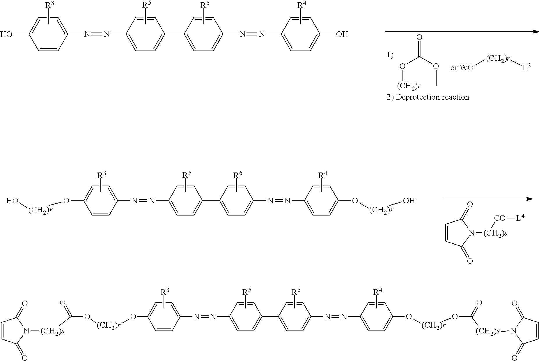
- the azo compound represented by the general formula (1) can be easily synthesized, for example, by the following method. Namely, a diazonium salt is synthesized by the diazotization reaction between a benzidine derivative and sodium nitrite. Then, the diazonium salt mixture obtained in the above process is reacted with a phenol derivative to obtain an azo compound having a hydroxy group.
- the azo compound thus obtained is reacted with carboxylic acid, carboxylic acid chloride, carboxylic anhydride, or an alkyl halide, each having a polymerizable functional group such as acryloyloxy group or maleimide group in the following scheme to obtain an azo compound having a polymerizable functional group.
- R 3 to R 6 are as defined in the general formula (1), R 20 represents hydrogen or a methyl group, p represents an integer of 1 to 18, and L 1 represents a hydroxyl group, a chlorine atom, or a pivaloyl group);
- R 3 to R 6 are as defined in the general formula (1), r represents an integer of 1 to 18, s represents an integer of 1 to 4, w represents a hydrogen atom, or a protective group such as an acetyl group, a benzoyl group, a tetrahydropyranyl group, a methoxymethyl group, or a t-butyldimethylsilyl group, L 3 represents a chlorine atom, a bromine atom, an iodine atom, or a sulfonate ester group such as a methanesulfonyloxy group, and L 4 represents a hydroxyl group, a chlorine atom, or a pivaloyloxy group);
- R 3 to R 6 are as defined in the general formula (1), t represents an integer of 1 to 18, u represents an integer of 1 to 4, X represents a hydrogen atom, or a protective group such as acetyl group, benzoyl group, tetrahydropyranyl group, methoxymethyl group, or t-butyldimethylsilyl group, and L 5 and L 6 each independently represents a hydroxyl group, a chlorine atom, or a pivaloyloxy group).
- the composition for photo-alignment film of the present invention is not specifically limited as long as it contains the azo compound represented by the general formula (1) and may include only the azo compound represented by the general formula (1). Also, it is possible to add other components, for example, additives such as solvents for improving coatability to the substrate, polymerization initiators, polymer materials for adjusting viscosity of the composition, leveling agents, thixotropic agents, gelatinizers, thickeners, surfactants, ultraviolet absorbers, infrared absorbers, antioxidants, and surface treating agents as long as alignment capability of the liquid crystal does not drastically deteriorate.
- additives such as solvents for improving coatability to the substrate, polymerization initiators, polymer materials for adjusting viscosity of the composition, leveling agents, thixotropic agents, gelatinizers, thickeners, surfactants, ultraviolet absorbers, infrared absorbers, antioxidants, and surface treating agents as long as alignment capability of the liquid crystal does not drastically deteriorate.
- the solvent which can be used in the composition for photo-alignment film of the present invention, is not specifically limited as long as it can dissolve the azo compound represented by the general formula (1), and examples thereof include N-methyl pyrrolidone, 2-butoxyethanol, N,N-dimethylformamide, ⁇ -butyrolactone, dimethyl sulfoxide, ethylene glycol, toluene, tetrahydrofuran, chlorobenzene, dimethylformamide, ⁇ -butyrolactone, dimethyl sulfoxide, ethylene glycol, toluene, tetrahydrofuran, chlorobenzene, and N,N-dimethyl acetamide.
- a solution of N-methyl pyrrolidone, butylcellosolve, or N,N-dimethylformamide is preferable because the solution is excellent in coatability to the substrate made of glass and a uniform film can be obtained.
- These solvents are preferably selected taking account of coatability and a volatilization rate of the solvent after coating, and two or more kinds thereof can be used in combination.
- the concentration of the azo compound represented by the general formula (1) is adjusted to at least 0.2% by mass, and particularly preferably within a range from 0.5 to 10% by mass.
- the polymer material for adjusting viscosity of the composition for photo-alignment film of the present invention includes, for example, a material which can form a film on the substrate and has high solubility to the solvent, and is also excellent in compatibility with the azo compound represented by the general formula (1).
- Specific examples thereof include polyvinyl alcohol, polyimide, polymaleimide, polyester, and polyamide.
- polyimide is particularly preferable because it is excellent in heat resistance and film forming properties on the substrate.
- the content of these polymer materials is preferably 60% or less, and particularly preferably 30% or less, based on the solid content of the photo-alignment film composition.
- a small amount of a thermal polymerization initiator or a photopolymerization initiator is preferably added for the purpose of increasing a polymerization rate.
- these polymerization initiators known polymerization initiators can be used. Since liquid crystal display characteristics may deteriorate when the amount is too large, the content of the polymerization initiator is preferably adjusted to 5% or less based on the solid content.
- an azo compound (1-1) in which at least one of R 3 and R 4 is —CONR 8 R 9 (wherein R 8 and R 9 each independently represents a hydrogen atom or an alkyl group having 1 to 6 carbon atoms) among the azo compound represented by the general formula (1) in combination with an azo compound represented by the general formula (2) because a photo-alignment film, which has high sensitivity and attains sufficient liquid crystal alignment properties in a low dose, can be obtained.
- a photo-alignment film which has particularly high sensitivity to ultraviolet light and visible light and also has sufficient liquid crystal alignment capability in a low dose, can be obtained.
- a photo-alignment film having an absolute value of an order parameter of 0.02 or more can be obtained at a light intensity of 250 mJ or less:
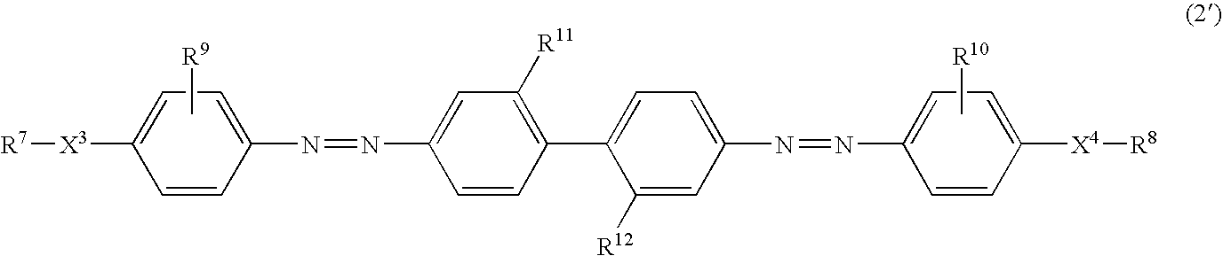
- R 7 and R 8 represent the same groups as those represented by R 1 and R 2 in the general formula (1)
- X 3 represents the same group represented by X 1 in the general formula (1)
- X 4 represents the same group represented by X 2 in the general formula (1)
- R 9 and R 10 each independently represents a carboxy group which may be bonded to an alkali metal to form a salt
- R 11 and R 12 represent the same groups as those represented by R 5 and R 6 in the general formula (1)).
- R 11 and R 12 each independently represents a carboxy group, a sulfo group, a nitro group, an amino group, or a hydroxy group, provided that the carboxy group or sulfo group may be bonded to an alkali metal to form a salt.
- a functional group having high affinity with a transparent electrode made of glass or ITO is preferable, and a carboxy group and a sulfo group are more preferable, and a sulfo group is particularly preferable.
- a compound represented by the general formula (2′) in which R 11 and R 12 are substituted on the 2- and 2′-positions of the 4,4′-bis(phenylazo)biphenyl backbone is particularly preferable because excellent photo-alignment properties are obtained:
- composition for photo-alignment film containing a compound represented by the general formula (1-1′) and a compound represented by the general formula (2′) can be exemplified as a preferable aspect.
- a mixing ratio of the azo compound (1-1) to a compound represented by the general formula (2) is preferably a mixing ratio so that a ratio of the content of the azo compound (1-1) is from 0.02 to 0.5 based on the sum of the content of the azo compound (1-1 ) and the content of the compound represented by the general formula (2).
- the mixing ratio is from 0.05 to 0.3, sufficient liquid crystal alignment capability can be obtained in a low dose.
- composition has high sensitivity
- a complex is formed by the interaction between an amide group of the azo compound (1-1 ) and a carboxy group of the compound represented by the general formula (2), and sensitivity to light increases as compared with the case where only the compound represented by the general formula (2) is used, and thus it becomes easy to realign an azo group.
- the method for producing a photo-alignment film of the present invention includes the steps of optionally adjusting viscosity of the photo-alignment film composition using the solvent or polymer material, coating the solution of the photo-alignment film composition on a substrate, and aligning the azo compound represented by the general formula (1) (both compounds when an azo compound represented by the general formula (2) is included) through light having anisotropy to obtain a photo-alignment film.
- a polymerizable functional group is polymerized by heating or irradiating with light after a photo-aligning treatment.
- the substrate used in the present invention is a substrate which is usually used in a liquid crystal display including a photo-alignment film, and particularly preferably a substrate having heat resistance enough to endure heat in the production of a liquid crystal display.
- the substrate include substrate made of glass or a heat-resistant polymer.
- the substrate is used in the state of being provided with a transparent electrode made of ITO on the surface thereof.
- the composition for photo-alignment film of the present invention is coated on a substrate using a method such as a spin coating method, a printing method, a die coating method, or a dipping method, and, after drying, a photo-alignment operation of the resulting coating film is conducted.
- a printing method is excellent in mass productivity and therefore particularly preferable.
- Photo-alignment is conducted by irradiating with light which can serve as light having anisotropy in the coating film.
- the coating film is irradiated with polarized light such as linearly polarized light or elliptically polarized light, or irradiated with unpolarized light from a tilted direction to a film plane.
- the polarized light may be linearly polarized light or elliptically polarized light, but is preferably linearly polarized light having a high extinction ratio so as to efficiently conduct photo-alignment.
- an incidence angle of unpolarized light is preferably within a range from 10° to 80° to a glass substrate normal line, and is most preferably from 20° to 60° taking account of uniformity of irradiation energy on the irradiated surface, the resulting pre-tilt angle, and alignment efficiency.
- Light to be irradiated is light in a range in which the azo compound represented by the general formula (1) has absorption. Specifically, ultraviolet light within a wavelength of 300 to 500 nm in which strong absorption attributed to ⁇ * transition of azobenzene is present.
- Examples of the light source for light to be irradiated include a xenon lamp, a high-pressure mercury-vapor lamp, an ultrahigh-pressure mercury-vapor lamp, a metal halide lamp, and an ultraviolet laser such as He—Cd laser or YAG laser.
- An ultrahigh-pressure mercury-vapor lamp is particularly preferable because emission intensity of an ultraviolet light having a wavelength of 365 nm is large, which is closer to a maximum absorption wavelength of the azo compound represented by the general formula (1).
- R 1 and R 2 of the azo compound represented by the general formula (1) is a polymerizable functional group
- a polymerization operation is conducted.
- the polymerization operation is conducted by thermal polymerization, it is conducted by heating a substrate which was coated with the photo-alignment film composition and then subjected to the photo-alignment operation, as described above.
- the heating temperature is preferably within a range from 100 to 300° C., and more preferably from 100 to 200° C.
- the polymerization operation is conducted by irradiation with light, it is preferably to irradiate with light having a wavelength, which is not absorbed by an azobenzene backbone, so as not to cause turbulence of an alignment state of already obtained material for photo-alignment film, namely, light having a wavelength which is different from that imparts liquid crystal alignment capability.
- More stable photo-alignment film is obtained by conducting the polymerization operation and a liquid crystal display capable of maintaining a high voltage-holding ratio by using the photo-alignment film.
- the photo-alignment film produced by the composition for photo-alignment film of the present invention is used for the purpose of mainly aligning a liquid crystal composition, and examples thereof will now be described but are not to be considered as limiting.
- a liquid crystal display including a photo-alignment film made of the composition for photo-alignment film of the present invention is produced by a conventionally known method.
- An example of the method for producing a TN type liquid crystal display will now be described.
- the composition for photo-alignment film of the present invention is coated and dried, and then an aligning treatment is conducted by means of visible light or ultraviolet light. Then, surfaces of the photo-alignment films are allowed to face each other via a spacer so as to make alignment directions of the respective photo-alignment films to intersect perpendicularly each other, and two substrates are laminated using a sealing material.
- a liquid crystal is filled into the space between two substrates through a pore opened when laminated using the sealing material.
- a TN type liquid crystal display can be produced by laminating a polarizing plate on the external side of the resulting liquid crystal cell so that the alignment direction of a photo-alignment film in the respective substrates and the direction of polarized light transmitted agree.
- An optically anisotropic body can also be produced by aligning a liquid crystal compound having a polymerizable group using a photo-alignment film made of the composition for photo-alignment film of the present invention, followed by polymerization. It is produced by a conventionally known method, and an example thereof will now be described.
- the composition for photo-alignment film of the present invention is coated and dried and then an aligning treatment is conducted by means of visible light or ultraviolet light.
- a material such as polymerizable liquid crystal composition capable of forming an optically anisotropic body is coated, or interposed between two substrate followed by polymerization, thereby making it possible to produce an optically anisotropic body.
- Example 3 the esterification reaction was conducted to obtain a compound No. A-8 from the compound No. A-1 obtained in Example 1 and 4-(6-acryloyloxyhexyloxy)benzoic acid.
- Example 6 B-1 obtained in Example 6 was suspended in 50 ml of pyridine, and a solution prepared by dissolving the acid chloride prepared by the above method in 3.0 ml of tetrahydrofuran was added at room temperature. After stirring at room temperature for 4 hours, the reaction solution was poured into an aqueous 1 N hydrochloric acid, followed by extraction with dichloromethane. The organic layer was washed in turn with an aqueous 2 N hydrochloric acid and water, and then dried over anhydrous magnesium sulfate.
- photo-alignment films were produced by the following method using compounds Nos. A-1, A-7, B-1, C-1, C-5, and C-7.
- photo-alignment films were produced by the following method using compounds Nos. A-8, A-10, and B-8.
- the surface of the resulting coating film was irradiated with ultraviolet parallel light having a wavelength of about 365 nm from an angle of 45° diagonally with the glass substrate through a band pass filter using an ultrahigh-pressure mercury vapor lamp.
- the exposure amount was 5 J/cm 2 in terms of integrated light quantity.
- the photo-alignment film thus obtained was thermally polymerized by heating under a nitrogen atmosphere at 150° C. for one hour.
- An epoxy-based adhesive containing silica beads having a diameter of 10 ⁇ m (manufactured by Mitsui Chemicals under the trade name of “Struct Bond XN-5A”) was coated on the peripheral surface of a photo-alignment film of a glass substrate with a photo-alignment film, excluding a liquid crystal filling port. After preliminarily curing at 80° C. for 30 minutes, another glass substrate with a photo-alignment film, which is not coated with an adhesive, was laid so that alignment surfaces are perpendicularly intersected each other, followed by contact bonding and further curing at 150° C. for 90 minutes.
- a liquid crystal composition for driving TFT (manufactured by Dainippon Ink and Chemicals, Inc. under the trade name of “11-3323”) was poured from a liquid crystal filling port under vacuum, and then the liquid crystal filling port was sealed with an epoxy-based adhesive to obtain TN liquid crystal cells for evaluation.
- the TN liquid crystal cells for evaluation were heated to the temperature higher than a transition temperature of the liquid crystal, and then slowly cooled to room temperature, and then subjected to evaluation.
- a polarizing microscope equipped with a photomultiplier under cross-nicol condition was used. Assumed that a light transmittance when light from a tungsten lamplight source of the polarizing microscope was completely shielded is 0% and that a light transmittance when a polarizing plate is applied on parallel-nicol in the state where a sample is not placed on a sample stage is 100%, an output from the photomultiplier was reduced.
- the TN liquid crystal cells were arranged in the direction in which the light transmittance increases most remarkably in the state where no voltage is applied, and then a voltage of 0 to 5 V was applied between electrodes of the TN liquid crystal cells, followed by sweeping, thereby obtaining a voltage-light transmittance (V-T) curve.
- V-T voltage-light transmittance
- Contrast ratio light transmittance when 4 V is applied/light transmittance when 0 V is applied (measured at room temperature)
- TN liquid crystal cell for evaluation were allowed to stand at 80° C. for 1000 hours, and alignment properties were visually evaluated, and also a voltage-holding ratio was measured.
- a voltage-holding ratio was measured by the above evaluation procedure.
- a change rate relative to an initial value calculated from a difference in a voltage-holding ratio before and after a thermal endurance test was used as an indicator for evaluation of thermal endurance.
- TN liquid crystal cells were produced in the same manner as in Example 10, except that each of the compounds represented by the formulas (a) and (b) was used.
- TN liquid crystal cells were produced in the same manner as in Example 16, except that each of the compounds represented by the formulas (c) and (d) was used.
- the liquid crystal alignment properties, voltage-holding ratio, and thermal endurance were evaluated.
- compositions containing a compound represented by the general formula (1) and a compound represented by the general formula (2) are shown below.
- Each of the resulting compositions for photo-alignment films (1) to (9) was coated on a glass substrate using a spin coater and then dried at 100° C. for one minute.
- the surface of the resulting coating film was irradiated with light according to the following irradiation conditions A and B to obtain a photo-alignment film.
- liquid crystal alignment capability order parameter, alignment minimum dose
- Linear polarized and parallel light of visible ultraviolet light having a wavelength of about 300 to 500 nm was irradiated from the direction perpendicular to a glass substrate through a wavelength cut filter and a polarization filter using an ultrahigh-pressure mercury vapor lamp to obtain a photo-alignment film.
- Parallel light of unpolarized visible ultraviolet light having a wavelength of about 300 to 500 nm (irradiation energy: 50 mW/cm 2 , integrated light quantity: 50, 100, 150, 200, 250, 300, 400, or 500 mJ) was irradiated from an angle of 45° diagonally with a glass substrate through a wavelength cut filter using an ultrahigh-pressure mercury vapor lamp to obtain a photo-alignment film.
- An order parameter was calculated from an absorbance, and anisotropy and its direction of a photo-alignment film were evaluated.
- a polarization visible ultraviolet spectrophotometer was used for the measurement of an absorbance.
- the order parameter shows a positive value when an azo compound is aligned in parallel to the direction of polarized light irradiated on an alignment film, while the order parameter shows a negative value when the azo compound is aligned in perpendicular to the direction of polarized light irradiated on the alignment film.
- a photo-alignment film produced at an integrated light quantity of 100 mJ was used.
- a ⁇ denotes an absorbance when the polarization direction of ultraviolet light irradiated for alignment of a photo-alignment film is in parallel to the direction of polarized light which is incident for measurement of an absorbance
- a ⁇ denotes an absorbance when the polarization direction of ultraviolet light irradiated for alignment of a photo-alignment film is in perpendicular to the direction of polarized light which is incident for measurement of an absorbance
- An epoxy-based adhesive containing silica beads having a diameter of 10 ⁇ m (manufactured by Mitsui Chemicals under the trade name of “Struct Bond XN-5A”) was coated on the peripheral surface of a photo-alignment film of a glass substrate with a photo-alignment film, excluding a liquid crystal filling port. After preliminarily curing at 80° C. for 30 minutes, another glass substrate, which is not coated with an adhesive, was laid so that alignment surfaces are perpendicularly intersected each other, followed by contact bonding and further curing at 150° C. for 90 minutes. Subsequently, a liquid crystal composition for driving TFT (manufactured by Dainippon Ink and Chemicals, Inc. under the trade name of “11-3323”) was poured from a liquid crystal filling port under vacuum, and then the liquid crystal filling port was sealed with an epoxy-based adhesive to obtain TN liquid crystal cells for evaluation.
- a liquid crystal composition for driving TFT manufactured by Da
- TN liquid crystal cells were produced using a photo-alignment film produced at an integrated light quantity of 20, 40, 60, 80, 100, 150, or 200 mJ.
- TN liquid crystal cells were produced using a photo-alignment film produced at an integrated light quantity of 50, 100, 150, 200, 250, 300, 400, or 500 mJ.
- the integrated light quantity of 100 mJ or less is a target value.
- the integrated light quantity of 300 mJ or less is a target value.
- a glass substrate with no photo-alignment film was laminated on a glass substrate by the above method. Assumed that a light transmittance at 400 to 700 nm in the state where a polarizing plate is applied on parallel-nicol is 100%, a light transmittance in the case of a cross-nicol of the resulting TN liquid crystal cells and a light transmittance in the case of a parallel-nicol were measured using a visible ultraviolet spectrophotometer. Integrated light quantity of a photo-alignment film produced at the smallest integrated light quantity among TN evaluation cells in which a difference in light transmittance is 90% or more was taken as an alignment minimum dose.
- the photo-alignment films produced by using the compound No. C-1 and the compound No. C-7 alone as the azo compound (1-1) exhibit excellent alignment properties and high voltage-holding ratio even at high temperature as shown in Table 6.
- the photo-alignment films of Examples 19 to 23 obtained by mixing a compound represented by the formula (a) as the compound represented by the general formula (2) with an azo compound (1-1) have improved sensitivity to photo-alignment properties, and a liquid crystal can be aligned at a small dose.
- These photo-alignment films are excellent as compared with the photo-alignment film of Comparative Example 6 obtained by using the compound (a) alone.
- the photo-alignment films of Examples 19 to 23 exhibit higher sensitivity than that of the photo-alignment film of Example 26 which contains the azo compound (1-1) in the proportion of 0.6 based on the sum of the content of an azo compound (1) and a compound represented by the general formula (2).
- an absolute value of an order parameter could be adjusted to more than 0.02 at an alignment minimum dose of 80 mJ or less in the irradiation condition A, or an alignment minimum dose of 250 mJ or less in the irradiation condition B.
- FIG. 1 is a graph showing a relation between a value of a ratio of the content of a compound represented by the general formula (1-1) to the sum of the content of a compound represented by the general formula (1-1) and the content of a compound represented by the general formula (2), (content of the compound represented by the general formula (1-1)/(content of the compound represented by the general formula (1-1)+content of the compound represented by the general formula (2)), as a “composition ratio”, and an order parameter.
- FIG. 2 is a graph showing a relation between the “composition ratio”, and an alignment minimum dose.
- the alignment minimum dose was 100 mJ or less in terms of an integrated light quantity in the irradiation condition A, and was 300 mJ or less in terms of an integrated light quantity in the irradiation condition B, and thus all target values were achieved.
- the azo compound of the present invention since the azo compound is easily aligned in a fixed direction to a polarization plane or an incidence plane by irradiation with light having anisotropy such as polarized light or incident light from a tilted direction to a film plane, and thus a film having high anisotropy in the plane and a high alignment-regulating force is obtained.
- the resulting alignment film exhibits a high voltage-holding ratio. Therefore, the alignment film is industrially useful.
Landscapes
- Chemical & Material Sciences (AREA)
- Physics & Mathematics (AREA)
- Organic Chemistry (AREA)
- Nonlinear Science (AREA)
- Mathematical Physics (AREA)
- Crystallography & Structural Chemistry (AREA)
- General Physics & Mathematics (AREA)
- Optics & Photonics (AREA)
- Spectroscopy & Molecular Physics (AREA)
- Chemical Kinetics & Catalysis (AREA)
- Liquid Crystal (AREA)
- Addition Polymer Or Copolymer, Post-Treatments, Or Chemical Modifications (AREA)
- Organic Low-Molecular-Weight Compounds And Preparation Thereof (AREA)
Abstract

(wherein, R1 and R2 each independently represents a hydroxy group, or a polymerizable functional group selected from the group consisting of a (meth)acryloyl group, a (meth)acryloyloxy group, a (meth)acrylamide group, a vinyl group, a vinyloxy group, and a maleimide group; X1 represents single bond when R1 is a hydroxy group and represents a linking group represented by -(A1-B1)m- when R1 is a polymerizable functional group; X2 represents a single bond when R2 is a hydroxy group and represents a linking group represented by -(A2-B2)n- when R2 is a polymerizable functional group; R3 and R4 each independently represents —OR7, a hydroxyalkyl group having 1 to 4 carbon atoms, or —CONR8R9; and R5 and R6 each independently represents a carboxy group, a sulfo group, a nitro group, amino group, or a hydroxy group).
Description

- [Non-patent reference 1] Molecular Crystals and Liquid Crystals, 2000 (352), p 27, the same document 2001 (360), p 81, and Liquid Crystals, 2002 (29), p 1321).
- [Patent reference 1] Japanese Unexamined Patent Application, First Publication No. 2002-250924.

(wherein, R1 and R2 each independently represents a hydroxy group, or a polymerizable functional group selected from the group consisting of a (meth)acryloyl group, a (meth)acryloyloxy group, a (meth)acrylamide group, a vinyl group, a vinyloxy group, and a maleimide group; X1 represents single bond when R1 is a hydroxy group and represents a linking group represented by -(A1-B1)m- when R1 is a polymerizable functional group; X2 represents a single bond when R2 is a hydroxy group and represents a linking group represented by -(A2-B2)n- when R2 is a polymerizable functional group, wherein A1 is bonded to R1, A2 is bonded to R2, and B1 and B2 each is bonded to an adjacent phenylene group; A1 and A2 each independently represents a single bond, or a phenylene or arylene group which may have a linear alkylene group having 1 to 18 carbon atoms, a branched alkylene group having 1 to 18 carbon atoms, or a linear or branched alkoxy group having 1 to 18 carbon atoms; B1 and B2 each independently represents a single bond, —O—, —CO—O—, —O—CO—, —CO—NH—, —NH—CO—, —NH—CO—O—, or —O—CO—NH—; m and n each independently represents an integer of 0 to 4, provided that a plurality of A1(s), B1(s), A2(s) and B2(s) is the same or different when m or n is 2 or more, A1 or A2 interposed between two B1(s) or B2(s) is not a single bond, and a combination of A1 and B1 or a combination of A2 and B2 is not a combination of only a linear alkylene group and —O—; R3 and R4 each independently represents —OR7 (wherein, R7 represents an alkyl group having 2 to 6 carbon atoms, a cycloalkyl group having 3 to 6 carbon atoms, or an alkyl group having 1 to 6 carbon atoms substituted with a lower alkoxy group having 1 to 6 carbon atoms), a hydroxyalkyl group having 1 to 4 carbon atoms, or —CONR8R9 (wherein, R8 and R9 each independently represents a hydrogen atom or an alkyl group having 1 to 6 carbon atoms); and R5 and R6 each independently represents a carboxy group, a sulfo group, a nitro group, amino group, or a hydroxy group, provided that a carboxy group and a sulfo group may be bonded to an alkali metal to form a salt).

(wherein, p represents an integer of 1 to 18).

(wherein, R1 to R6, and X1 and X2 represent the same group as those represented by the general formula (1)).

(wherein, R1 to R6, X1 and X2 represent the same groups as those represented by the general formula (1), provided that at least one of R3 and R4 represents —CONR8R9 (wherein, R8 and R9 each independently represents a hydrogen atom or an alkyl group having 1 to 6 carbon atoms)).
(Production Method)

(wherein, R3 to R6 are as defined in the general formula (1), R20 represents hydrogen or a methyl group, p represents an integer of 1 to 18, and L1 represents a hydroxyl group, a chlorine atom, or a pivaloyl group);
(wherein, R3 to R6 are as defined in the general formula (1), r represents an integer of 1 to 18, s represents an integer of 1 to 4, w represents a hydrogen atom, or a protective group such as an acetyl group, a benzoyl group, a tetrahydropyranyl group, a methoxymethyl group, or a t-butyldimethylsilyl group, L3 represents a chlorine atom, a bromine atom, an iodine atom, or a sulfonate ester group such as a methanesulfonyloxy group, and L4 represents a hydroxyl group, a chlorine atom, or a pivaloyloxy group);

(wherein, R3 to R6 are as defined in the general formula (1), t represents an integer of 1 to 18, u represents an integer of 1 to 4, X represents a hydrogen atom, or a protective group such as acetyl group, benzoyl group, tetrahydropyranyl group, methoxymethyl group, or t-butyldimethylsilyl group, and L5 and L6 each independently represents a hydroxyl group, a chlorine atom, or a pivaloyloxy group).

| TABLE 1 | ||||||||
| Compound No. | R1 | X1 | R2 | X2 | R3 | R4 | R5 | R6 |
| A-1 | OH | Single bond | OH | Single bond | 3-OCH2CH3 | 3′-OCH2CH3 | 2-SO3Na | 2′-SO3Na |
| A-2 | OH | Single bond | OH | Single bond | 3-OCH2CH3 | 3′-OCH2CH3 | 2-SO3H | 2′-SO3H |
| A-3 | OH | Single bond | OH | Single bond | 3-OCH2CH2-CH3 | 3′-OCH2CH2-CH3 | 2-SO3Na | 2′-SO3Na |
| A-4 | OH | Single bond | OH | Single bond | 3-OCH2CH2-CH3 | 3′-OCH2CH2-CH3 | 2-SO3H | 2′-SO3H |
| A-5 | OH | Single bond | OH | Single bond | 3-OCH-(CH3)2 | 3′-OCH(CH3)2 | 2-SO3Na | 2′-SO3Na |
| A-6 | OH | Single bond | OH | Single bond | 3-OCH-(CH3)2 | 3′-OCH(CH3)2 | 2-SO3H | 2′-SO3H |
| A-7 | OH | Single bond | OH | Single bond | 3-OCH2O-CH3 | 3′-OCH2OCH3 | 2-SO3Na | 2′-SO3Na |
| A-8 | CH2CH- | Formula (3a) | CH2CH-COO | Formula (3a) | 3-OCH2CH3 | 3′-OCH2CH3 | 2-SO3Na | 2′-SO3Na |
| COO | ||||||||
| A-9 | CH2CH- | Formula (3b) | CH2CH-COO | Formula (3b) | 3-OCH2CH3 | 3′-OCH2CH3 | 2-SO3Na | 2′-SO3Na |
| COO | ||||||||
| A-10 | CH2CH- | Formula (3a) | CH2CH-COO | Formula (3a) | 3-OCH2O-CH3 | 3′-OCH2OCH3 | 2-SO3Na | 2′-SO3Na |
| COO | ||||||||
| TABLE 2 | ||||||||
| Compound No. | R1 | X1 | R2 | X2 | R3 | R4 | R5 | R6 |
| B-1 | OH | Single bond | OH | Single bond | 3-CH2OH | 3′-CH2OH | 2-SO3Na | 2′-SO3Na |
| B-2 | OH | Single bond | OH | Single bond | 3-CH2OH | 3′-CH2OH | 2-SO3H | 2′-SO3H |
| B-3 | OH | Single bond | OH | Single bond | 3-CH(OH)CH3 | 3′-CH(OH)CH3 | 2-SO3Na | 2′-SO3Na |
| B-4 | OH | Single bond | OH | Single bond | 3-CH(OH)CH3 | 3′-CH(OH)CH3 | 2-SO3H | 2′-SO3H |
| B-5 | OH | Single bond | OH | Single bond | 3-CH2CH2OH | 3′-CH2CH2OH | 2-SO3Na | 2′-SO3Na |
| B-6 | OH | Single bond | OH | Single bond | 3-CH2CH2OH | 3′-CH2CH2OH | 2-SO3H | 2′-SO3H |
| B-7 | CH2CHCOO | Formula (3c) | CH2CHCOO | Formula (3c) | 3-CH2OH | 3′-CH2OH | 2-SO3Na | 2′-SO3Na |
| B-8 | CH2CHCOO | Formula (3a) | CH2CHCOO | Formula (3a) | 3-CH2OH | 3′-CH2OH | 2-SO3Na | 2′-SO3Na |
| B-9 | CH2CHCOO | Formula (3b) | CH2CHCOO | Formula (3b) | 3-CH2OH | 3′-CH2OH | 2-SO3Na | 2′-SO3Na |
| B-10 | CH2CHCOO | Formula (3d) | CH2CHCOO | Formula (3d) | 3-CH2OH | 3′-CH2OH | 2-SO3Na | 2′-SO3Na |
| B-11 | CH2C(CH3)COO | Formula (3a) | CH2C(CH3)COO | Formula (3a) | 3-CH2OH | 3′-CH2OH | 2-SO3Na | 2′-SO3Na |
| TABLE 3 | ||||||||
| Compound No. | R1 | X1 | R2 | X2 | R3 | R4 | R5 | R6 |
| C-1 | OH | Single bond | OH | Single bond | 3-CONH2 | 3′-CONH2 | 2-SO3Na | 2′-SO3Na |
| C-2 | OH | Single bond | OH | Single bond | 3-CONH2 | 3′-CONH2 | 2-SO3H | 2′-SO3H |
| C-3 | OH | Single bond | OH | Single bond | 3-CONH-(CH3) | 3′-CONH(CH3) | 2-SO3Na | 2′-SO3Na |
| C-4 | OH | Single bond | OH | Single bond | 3-CONH-(CH3) | 3′-CONH(CH3) | 2-SO3H | 2′-SO3H |
| C-5 | OH | Single bond | OH | Single bond | 3-CON-(CH3)2 | 3′-CON(CH3)2 | 2-SO3Na | 2′-SO3Na |
| C-6 | OH | Single bond | OH | Single bond | 3-CON(CH3)2 | 3′-CON(CH3)2 | 2-SO3H | 2′-SO3H |
| C-7 | OH | Single bond | OH | Single bond | 3-CONH-(n-C4H9) | 3′-CONH(n-C4H9) | 2-SO3Na | 2′-SO3Na |
| C-8 | OH | Single bond | OH | Single bond | 3-CONH-(n-C4H9) | 3′-CONH(n-C4H9) | 2-SO3H | 2′-SO3H |
| C-9 | CH2CH- | Formula (3a) | CH2CH- | Formula (3a) | 3-CONH2 | 3′-CONH2 | 2-SO3Na | 2′-SO3Na |
| COO | COO | |||||||
| C-10 | CH2CH- | Formula (3a) | CH2CH- | Formula (3a) | 3-CONH-(n-C4H9) | 3′-CONH(n-C4H9) | 2-SO3Na | 2′-SO3Na |
| COO | COO | |||||||
| TABLE 4 | ||||||||
| Compound | ||||||||
| No. | R1 | X1 | R2 | X2 | R3 | R4 | R5 | R6 |
| D-1 | OH | Single bond | OH | Single bond | 3-OCH2CH3 | 3′-OCH2CH3 | 2-CO2H | 2′-CO2H |
| D-2 | OH | Single bond | OH | Single bond | 3-CH2OH | 3′-CH2OH | 2-CO2H | 2′-CO2H |
| D-3 | OH | Single bond | OH | Single bond | 3-CONH2 | 3′-CONH2 | 2-CO2H | 2′-CO2H |
| D-4 | OH | Single bond | OH | Single bond | 3-CONH-(n-C4H9) | 3-CONH-(n-C4H9) | 2-CO2H | 2′-CO2H |
| D-5 | CH2CH-COO | Formula (3a) | CH2CH-COO | Formula (3a) | 3-OCH2CH3 | 3′-OCH2CH3 | 2-CO2h | 2′-CO2H |
| D-6 | CH2CH-COO | Formula (3a) | CH2CH-COO | Formula (3a) | 3-CH2OH | 3′-CH2OH | 2-CO2H | 2′-CO2H |
| D-7 | CH2CH-COO | Formula (3a) | CH2CH-COO | Formula (3a) | 3-CONH-(n-C4H9) | 3′-CONH-(n-C4H9) | 2-CO2H | 2′-CO2H |
| D-8 | Formula (4) | Formula (3e) | Formula (4) | Formula (3e) | 3-OCH2CH3 | 3′-OCH2CH3 | 2-SO3Na | 2′-SO3Na |
| D-9 | Formula (4) | Formula (3f) | Formula (4) | Formula (3f) | 3-OCH2CH3 | 3′-OCH2CH3 | 2-SO3Na | 2′-SO3Na |
| D-10 | Formula (4) | Formula (3e) | Formula (4) | Formula (3e) | 3-CH2OH | 3′-CH2OH | 2-SO3Na | 2′-SO3Na |
| D-11 | Formula (4) | Formula (3e) | Formula (4) | Formula (3e) | 3-CON(CH3)2 | 3′-CON(CH3)2 | 2-SO3Na | 2′-SO3Na |
(Composition for Photo-alignment Film)

(wherein, R7 and R8 represent the same groups as those represented by R1 and R2 in the general formula (1), X3 represents the same group represented by X1 in the general formula (1), X4 represents the same group represented by X2 in the general formula (1), R9 and R10 each independently represents a carboxy group which may be bonded to an alkali metal to form a salt, and R11 and R12 represent the same groups as those represented by R5 and R6 in the general formula (1)).

(wherein, R7 to R12, and X3 and X4 represent the same groups as those represented by the general formula (2)).
| TABLE 5 | |
| Compound | |
| No. | 1H-NMR (dimethyl sulfoxide-d6) δ ppm |
| A-1 | 1.38 (t, J=6.8 Hz, 6H), 4.14 (q, J=6.8 Hz, 4H), 6.98 (d, |
| J=7.8 Hz, 2H), 7.4 to 7.55 (m, 6H), 7.69 (dd, J=2.0, | |
| 8.3 Hz, 2H), 8.31 (d, J=2.0 Hz, 2H) | |
| A-7 | 3.46 (s, 6H), 5.27 (s, 4H), 6.98 (d, J=8.3 Hz, 2H), |
| 7.45 (d, J=8.3 Hz, 2H), 7.54 (dd, J=2.4, 8.3 Hz, 2H), | |
| 7.62 (d, J=2.4 Hz, 2H), 7.68 (dd, J=2.0, 8.3 Hz, 2H), | |
| 8.30 (d, J=2.0 Hz, 2H) | |
| A-8 | 1.3 to 1.55 (m, 14H), 1.65 (m, 4H), 1.76 (m, 4H), 4.13 |
| (m, 12H), 5.94 (dd, J=1.8, 10.0 Hz, 2H), 6.18 (dd, | |
| J=10.0, 17.0 Hz, 2H), 6.33 (dd, J=1.8, 17.0 Hz, 2H), | |
| 7.15 (d, J=8.8 Hz, 4H), 7.52 (d, J=8.2 Hz, 2H), 7.61 | |
| (d, J=8.0 Hz, 2H), 7.73 (dd, J=2.1, 8.2 Hz, 2H), 7.85 | |
| (m, 4H), 8.12 (d, J=8.8 Hz, 4H), 8.50 (d, J=2.5 Hz, 2H) | |
| A-10 | 1.30 to 1.55 (m, 8H), 1.66 (m, 4H), 1.78 (m, 4H), 3.38 |
| (s, 6H), 4.13 (m, 8H), 5.34 (s, 4H), 5.94 (dd, J=1.8, | |
| 10.1 Hz, 2H), 6.18 (dd, J=10.1, 17.2 Hz, 2H), 6.33 | |
| (dd, J=1.8, 17.2 Hz, 2H), 7.14 (d, J=8.9 Hz, 4H), | |
| 7.52 (d, J=8.4 Hz, 2H), 7.60 (d, J=8.1 Hz, 2H), 7.72 | |
| (dd, J=2.2, 8.4 Hz, 2H), 7.83 (m, 4H), 8.12 (d, J=8.9 Hz, | |
| 4H), 8.43 (d, J=2.6 Hz, 2H) | |
| B-1 | 4.55 (s, 4H), 6.97 (d, J=8.7 Hz, 2H), 7.49 (d, |
| J=8.1 Hz, 2H), 7.71 (dd, J=2.2, 8.1 Hz, 2H), 7.74 | |
| (dd, J=2.5, 8.7 Hz, 2H), 7.97 (d, J=2.5 Hz, 2H), 8.31 | |
| (d, J=2.2 Hz, 2H), 10.3 (brd, 2H) | |
| B-8 | 1.3 to 1.55 (m, 8H), 1.66 (m, 4H), 1.76 (m, 4H), 4.13 |
| (m, 8H), 4.58 (s, 4H), 5.94 (dd, J=1.8, 10.3 Hz, 2H), 6.18 | |
| (dd, J=10.3, 17.2 Hz, 2H), 6.32 (dd, J=1.8, 17.2 Hz, 2H), | |
| 7.15 (d, J=8.8 Hz, 4H), 7.49 (d, J=8.4 Hz, 2H), 7.60 | |
| (d, J=7.7 Hz, 2H), 7.85 (dd, J=2.2, 7.7 Hz, 2H), 7.95 | |
| (d, J=8.4 Hz, 2H), 8.13 (m, 6H), 8.43 (d, J=2.2 Hz, 2H) | |
| C-1 | 6.68 (d, J=8.8 Hz, 2H), 7.36 (brd, 2H), 7.41 |
| (d, J=8.3 Hz, 2H), 7.64 (dd, J=2.4, 8.3 Hz, 2H), 7.80 | |
| (dd, J=2.4, 8.8 Hz, 2H), 8.28 (d, J=2.4 Hz, 2H), 8.46 | |
| (d, J=2.4 Hz, 2H), 9.87 (brd, 2H) | |
| C-5 | 2.9 (brd, 6H), 7.08 (d, J=8.8 Hz, 2H), 7.50 |
| (d, J=8.2 Hz, 2H), 7.72 (m, 4H), 7.88 (dd, J=2.4, | |
| 8.8 Hz, 2H), 8.32 (d, J=2.4 Hz, 2H) | |
| C-7 | 0.92 (t, J=7.1 Hz, 6H), 1.3 to 1.55 (m, 8H), |
| 3.29 (m, 4H), 6.35 (d, J=9.2 Hz, 2H), 7.55 (dd, J=2.3, | |
| 8.0 Hz, 2H), 7.63 (dd, J=2.9, 9.2 Hz, 2H), 8.21 (d, | |
| J=2.3 Hz, 2H), 8.33 (d, J=2.9 Hz, 2H) | |


- A: exhibit good alignment uniformly in one direction
- B: exhibit good alignment, but is inferior to A
- C: exhibit partial alignment, but defects exist
- D: exhibit no alignment (evaluated at room temperature)
(Voltage-Holding Ratio)
| TABLE 6 | |||||
| Liquid crystal | Liquid crystal | ||||
| alignment | alignment | Voltage-holding | Change in | ||
| properties | properties (visual) | ratio (%) | voltage- | ||
| Compound | Contrast | After thermal | After thermal | holding | |||
| Examples | No. | ratio | Initial | endurance test | Initial | endurance test | ratio (%) |
| Example 10 | A-1 | 89.5 | A | A | 93.2 | 92.3 | −0.97 |
| Example 11 | A-7 | 91.2 | A | A | 83.3 | 82.9 | −0.48 |
| Example 12 | B-1 | 92.4 | A | A | 90.5 | 90.1 | −0.44 |
| Example 13 | C-1 | 89.4 | B | B | 96.5 | 95.9 | −0.62 |
| Example 14 | C-5 | 88.3 | B | B | 93.2 | 92.9 | −0.32 |
| Example 15 | C-7 | 88.5 | B | B | 95.8 | 95.4 | −0.42 |
| Example 16 | A-8 | 88.2 | B | B | 96.1 | 96.2 | −0.10 |
| Example 17 | A-10 | 89.3 | A | A | 94.3 | 94.1 | −0.21 |
| Example 18 | B-8 | 88.9 | A | A | 95.4 | 95.2 | −0.21 |
| Comparative | (a) | 94.5 | A | A | 81.2 | 78.5 | −3.33 |
| Example 1 | |||||||
| Comparative | (b) | 91.3 | A | A | 21.1 | 18.5 | −12.32 |
| Example 2 | |||||||
| Comparative | (c) | 89.9 | B | B | 37.2 | 30.3 | −18.55 |
| Example 3 | |||||||
| Comparative | (d) | 87.5 | C | C | 89.2 | 89.1 | −0.11 |
| Example 4 | |||||||
| TABLE 7 | |||||||||
| Example | Example | Example | Example | Example | Comparative | Example | Example | Example | |
| Compound No. | 19 | 20 | 21 | 22 | 23 | Example 6 | 24 | 25 | 26 |
| Composition for photo- | (1) | (2) | (3) | (4) | (5) | (6) | (7) | (8) | (9) |
| alignment film | |||||||||
| (a) | 0.7 | 0.55 | 0.95 | 0.9 | 0.9 | 1 | 0.4 | ||
| C-1 | 0.3 | 0.45 | 0.05 | 0.1 | 1 | 0.6 | |||
| C-7 | 0.1 | 1 | |||||||
| Irradiation condition A | |||||||||
| (Order parameter) | −0.07 | −0.061 | −0.075 | −0.078 | −0.082 | −0.051 | −0.019 | −0.015 | −0.039 |
| (Alignment minimum dose) | 60 | 80 | 60 | 40 | 20 | 100 | >200 | >200 | 200 |
| Irradiation condition B | |||||||||
| (Order parameter) | −0.029 | −0.024 | −0.038 | −0.039 | −0.042 | −0.022 | −0.012 | −0.01 | −0.015 |
| (Alignment minimum dose) | 200 | 250 | 200 | 150 | 150 | 300 | >500 | >500 | >500 |
(Light Irradiation Conditions)
(Irradiation Condition A)
(wherein, A ∥ denotes an absorbance when the polarization direction of ultraviolet light irradiated for alignment of a photo-alignment film is in parallel to the direction of polarized light which is incident for measurement of an absorbance, and A⊥ denotes an absorbance when the polarization direction of ultraviolet light irradiated for alignment of a photo-alignment film is in perpendicular to the direction of polarized light which is incident for measurement of an absorbance).
(Alignment Minimum Dose)
Claims (10)


Applications Claiming Priority (7)
| Application Number | Priority Date | Filing Date | Title |
|---|---|---|---|
| JP2004194424 | 2004-06-30 | ||
| JP2004-194424 | 2004-06-30 | ||
| JPP2004-194424 | 2004-06-30 | ||
| JPP2004-257138 | 2004-09-03 | ||
| JP2004-257138 | 2004-09-03 | ||
| JP2004257138 | 2004-09-03 | ||
| PCT/JP2005/011844 WO2006003893A1 (en) | 2004-06-30 | 2005-06-28 | Azo compound, composition for optical alignment film using same, and method for producing optical alignment film |
Publications (2)
| Publication Number | Publication Date |
|---|---|
| US20070254220A1 US20070254220A1 (en) | 2007-11-01 |
| US7892711B2 true US7892711B2 (en) | 2011-02-22 |
Family
ID=35782700
Family Applications (1)
| Application Number | Title | Priority Date | Filing Date |
|---|---|---|---|
| US11/629,984 Active 2028-05-31 US7892711B2 (en) | 2004-06-30 | 2005-06-28 | Azo compound, composition for photo-alignment film using the same, and method for producing photo-alignment film |
Country Status (7)
| Country | Link |
|---|---|
| US (1) | US7892711B2 (en) |
| EP (1) | EP1767523B1 (en) |
| JP (1) | JP4629043B2 (en) |
| KR (1) | KR100819416B1 (en) |
| HK (1) | HK1106760A1 (en) |
| TW (1) | TWI360570B (en) |
| WO (1) | WO2006003893A1 (en) |
Cited By (2)
| Publication number | Priority date | Publication date | Assignee | Title |
|---|---|---|---|---|
| US20120035293A1 (en) * | 2010-07-07 | 2012-02-09 | Boydston Andrew J | On-demand photoinitiated polymerization |
| US11266495B2 (en) | 2019-10-20 | 2022-03-08 | Rxsight, Inc. | Light adjustable intraocular lens with a modulable absorption front protection layer |
Families Citing this family (22)
| Publication number | Priority date | Publication date | Assignee | Title |
|---|---|---|---|---|
| TWI406061B (en) * | 2005-11-10 | 2013-08-21 | Dainippon Ink & Chemicals | Composition for photoalignment film, optically anisotropic body and method of producing same |
| JP4950514B2 (en) * | 2006-02-27 | 2012-06-13 | 株式会社 日立ディスプレイズ | Manufacturing method and manufacturing apparatus for liquid crystal display device |
| JP4775796B2 (en) * | 2006-03-14 | 2011-09-21 | 独立行政法人物質・材料研究機構 | Liquid crystal alignment film, liquid crystal alignment agent, and liquid crystal display element |
| JP5549047B2 (en) * | 2006-05-30 | 2014-07-16 | 三菱化学株式会社 | Azo dyes for anisotropic dye films |
| JP5028055B2 (en) * | 2006-09-22 | 2012-09-19 | Dic株式会社 | Composition for optical alignment film and optical anisotropic body |
| JP4151746B2 (en) * | 2006-11-08 | 2008-09-17 | Dic株式会社 | Composition for photo-alignment film, photo-alignment film, and optical anisotropic body |
| DE102006062457A1 (en) * | 2006-12-28 | 2008-07-03 | Bayer Innovation Gmbh | Optical storage layer useful for recording analog or digital data and information comprises a photoaddressable polymer and an additive |
| EP1975687A1 (en) * | 2007-03-29 | 2008-10-01 | Rolic AG | Method of uniform and defect free liquid crystal aligning layers |
| JP2008304499A (en) * | 2007-06-05 | 2008-12-18 | Sony Corp | Optical compensation member, liquid crystal display device, composition for alignment layer, and alignment layer |
| JP5076810B2 (en) * | 2007-10-31 | 2012-11-21 | Dic株式会社 | Composition for photo-alignment film, photo-alignment film, and optical anisotropic body |
| JP2010175931A (en) * | 2009-01-30 | 2010-08-12 | Dic Corp | Composition for optical alignment film, optical alignment film, and optically anisotropic body |
| TWI373671B (en) | 2009-02-26 | 2012-10-01 | Au Optronics Corp | Alighment material composition and alignment layer |
| JP5776920B2 (en) * | 2009-06-17 | 2015-09-09 | Dic株式会社 | Method for producing biaxial retardation film |
| JP2012194297A (en) * | 2011-03-16 | 2012-10-11 | Nitto Denko Corp | Composition and method for manufacturing polarizing film using the same |
| US9353226B2 (en) | 2011-05-27 | 2016-05-31 | Fraunhofer-Gesellschaft zur Förderung der angewandten Forschung e.V. | Compounds containing (meth)acrylate groups and sulfonate or sulfate groups, polymers and condensates made therefrom and use of the polymers and condensates |
| JP5382468B2 (en) * | 2011-06-30 | 2014-01-08 | Dic株式会社 | Composition for optical alignment film and optical anisotropic body |
| JP5772864B2 (en) * | 2013-04-16 | 2015-09-02 | Dic株式会社 | Method for measuring tilt angle of alignment film, photo-alignment film, optical anisotropic body |
| JP6461544B2 (en) * | 2014-10-08 | 2019-01-30 | 株式会社ジャパンディスプレイ | Liquid crystal display device and manufacturing method thereof |
| CN113396359A (en) * | 2019-02-05 | 2021-09-14 | 日产化学株式会社 | Liquid crystal aligning agent, liquid crystal alignment film, and liquid crystal display element using same |
| KR20210137495A (en) * | 2019-03-12 | 2021-11-17 | 닛산 가가쿠 가부시키가이샤 | Liquid crystal aligning agent, liquid crystal aligning film, and liquid crystal display element using same |
| JP7463720B2 (en) * | 2019-12-25 | 2024-04-09 | Dic株式会社 | Azo Powder Composition |
| JP7453354B2 (en) * | 2020-04-20 | 2024-03-19 | 富士フイルム株式会社 | Photoalignment films, laminates, image display devices, and azo compounds |
Citations (11)
| Publication number | Priority date | Publication date | Assignee | Title |
|---|---|---|---|---|
| EP0525478A2 (en) | 1991-07-26 | 1993-02-03 | F. Hoffmann-La Roche Ag | Liquid crystal display cell |
| US20020098295A1 (en) | 2000-11-24 | 2002-07-25 | Hong Kong University Of Science And Technology | Method of manufacturing photo-alignment layer |
| JP2002250924A (en) | 2000-11-24 | 2002-09-06 | Hong Kong Univ Of Science & Technology | Method for manufacturing photo-alignment film |
| JP2004083810A (en) | 2002-08-28 | 2004-03-18 | Dainippon Ink & Chem Inc | Composition for vertically aligned membrane and method for producing vertically aligned membrane |
| JP2004302272A (en) | 2003-03-31 | 2004-10-28 | Hong Kong Univ Of Science & Technology | Composition for liquid crystal alignment film, liquid crystal alignment film, method for manufacturing liquid crystal alignment film and maleimide compound |
| JP2004361653A (en) | 2003-06-04 | 2004-12-24 | Hong Kong Univ Of Science & Technology | Ferroelectric liquid crystal element |
| JP2005049386A (en) | 2003-07-29 | 2005-02-24 | Dainippon Ink & Chem Inc | Method for manufacturing optical alignment layer, and optical alignment layer |
| JP2005173548A (en) | 2003-07-31 | 2005-06-30 | Dainippon Ink & Chem Inc | Optically anisotropic substance and method for manufacturing the same |
| JP2005173586A (en) | 2003-11-20 | 2005-06-30 | Hong Kong Univ Of Science & Technology | Liquid crystal pretilt angle imparting agent for optical alignment film, optical alignment film composition and method for manufacturing optical alignment film |
| JP2005173547A (en) | 2003-07-31 | 2005-06-30 | Dainippon Ink & Chem Inc | Method for manufacturing optically anisotropic substance |
| US7419620B2 (en) * | 2001-05-08 | 2008-09-02 | Rolic Ltd C/O Rolic Technologies Ltd | Dichroic mixtures |
-
2005
- 2005-06-28 TW TW094121550A patent/TWI360570B/en active
- 2005-06-28 KR KR1020077000016A patent/KR100819416B1/en active IP Right Grant
- 2005-06-28 WO PCT/JP2005/011844 patent/WO2006003893A1/en not_active Application Discontinuation
- 2005-06-28 JP JP2006528710A patent/JP4629043B2/en active Active
- 2005-06-28 US US11/629,984 patent/US7892711B2/en active Active
- 2005-06-28 EP EP05765249A patent/EP1767523B1/en active Active
-
2008
- 2008-01-15 HK HK08100489.0A patent/HK1106760A1/en unknown
Patent Citations (11)
| Publication number | Priority date | Publication date | Assignee | Title |
|---|---|---|---|---|
| EP0525478A2 (en) | 1991-07-26 | 1993-02-03 | F. Hoffmann-La Roche Ag | Liquid crystal display cell |
| US20020098295A1 (en) | 2000-11-24 | 2002-07-25 | Hong Kong University Of Science And Technology | Method of manufacturing photo-alignment layer |
| JP2002250924A (en) | 2000-11-24 | 2002-09-06 | Hong Kong Univ Of Science & Technology | Method for manufacturing photo-alignment film |
| US7419620B2 (en) * | 2001-05-08 | 2008-09-02 | Rolic Ltd C/O Rolic Technologies Ltd | Dichroic mixtures |
| JP2004083810A (en) | 2002-08-28 | 2004-03-18 | Dainippon Ink & Chem Inc | Composition for vertically aligned membrane and method for producing vertically aligned membrane |
| JP2004302272A (en) | 2003-03-31 | 2004-10-28 | Hong Kong Univ Of Science & Technology | Composition for liquid crystal alignment film, liquid crystal alignment film, method for manufacturing liquid crystal alignment film and maleimide compound |
| JP2004361653A (en) | 2003-06-04 | 2004-12-24 | Hong Kong Univ Of Science & Technology | Ferroelectric liquid crystal element |
| JP2005049386A (en) | 2003-07-29 | 2005-02-24 | Dainippon Ink & Chem Inc | Method for manufacturing optical alignment layer, and optical alignment layer |
| JP2005173548A (en) | 2003-07-31 | 2005-06-30 | Dainippon Ink & Chem Inc | Optically anisotropic substance and method for manufacturing the same |
| JP2005173547A (en) | 2003-07-31 | 2005-06-30 | Dainippon Ink & Chem Inc | Method for manufacturing optically anisotropic substance |
| JP2005173586A (en) | 2003-11-20 | 2005-06-30 | Hong Kong Univ Of Science & Technology | Liquid crystal pretilt angle imparting agent for optical alignment film, optical alignment film composition and method for manufacturing optical alignment film |
Non-Patent Citations (6)
| Title |
|---|
| A. X. Lupea et al. "Disazo-Pigments from Salicylamides" Chem. Bull. Univ. Timisoara, vol. 40, No. 54, 1995, pp. 57-62. |
| N. Novoseletski, et al.;"Alignment of Nematic Liquid Crystals by Photo-oriented layers;" Mol. Cryst. and Liq. Cryst.; vol. 352; 2000; pp. 27-35 (5 Sheets.). |
| Notice of Reasons for Rejection mailed on Oct. 27, 2009, issued on the Japanese Patent Application No. 2006-528710 and the English translation thereof. |
| S.I. Torgova, et al.; Influence of Chemical Structure on the Aligning Power of Photo-Oriented Films; Mol. Cryst. And Liq. Cryst.; vol. 360; 2001; pp. 81-91 (6 Sheets.). |
| Supplementary European Search Report dated Jul. 27, 2009 issued for EP Application No. 05765249.7. |
| V. Chigrinov, et al.; "Synthesis and properties of azo dye aligning layers for liquid crystal cells;" Liquid Crystals; vol. 29; No. 10; 2002; pp. 1321-1327. |
Cited By (4)
| Publication number | Priority date | Publication date | Assignee | Title |
|---|---|---|---|---|
| US20120035293A1 (en) * | 2010-07-07 | 2012-02-09 | Boydston Andrew J | On-demand photoinitiated polymerization |
| US8604098B2 (en) * | 2010-07-07 | 2013-12-10 | California Institute Of Technology | On-demand photoinitiated polymerization |
| US8933143B2 (en) | 2010-07-07 | 2015-01-13 | California Institute Of Technology | On-demand photoinitiated polymerization |
| US11266495B2 (en) | 2019-10-20 | 2022-03-08 | Rxsight, Inc. | Light adjustable intraocular lens with a modulable absorption front protection layer |
Also Published As
| Publication number | Publication date |
|---|---|
| JPWO2006003893A1 (en) | 2008-04-17 |
| JP4629043B2 (en) | 2011-02-09 |
| TWI360570B (en) | 2012-03-21 |
| KR20070052736A (en) | 2007-05-22 |
| TW200615365A (en) | 2006-05-16 |
| KR100819416B1 (en) | 2008-04-08 |
| US20070254220A1 (en) | 2007-11-01 |
| EP1767523A4 (en) | 2009-08-26 |
| EP1767523B1 (en) | 2011-08-24 |
| EP1767523A1 (en) | 2007-03-28 |
| HK1106760A1 (en) | 2008-03-20 |
| WO2006003893A1 (en) | 2006-01-12 |
Similar Documents
| Publication | Publication Date | Title |
|---|---|---|
| US7892711B2 (en) | Azo compound, composition for photo-alignment film using the same, and method for producing photo-alignment film | |
| JP5186734B2 (en) | Azo compound, composition for photo-alignment film, photo-alignment film and liquid crystal display element | |
| US6582776B2 (en) | Method of manufacturing photo-alignment layer | |
| JP7189296B2 (en) | Photoactive polymer material | |
| JP3883848B2 (en) | Method for producing photo-alignment film | |
| US6733958B2 (en) | Material for photo-alignment layer, photo-alignment layer and method of manufacturing the same | |
| JP5316740B2 (en) | Method for forming liquid crystal alignment film | |
| JP4900632B2 (en) | Photo-alignment film material, photo-alignment film and method for producing the same | |
| US8009264B2 (en) | Composition for photo-alignment film, photo-alignment film, and optically anisotropic medium | |
| JP4888690B2 (en) | Method for producing photo-alignment film | |
| TWI513714B (en) | Polymer for liquid crystal vertical alignment layer, liquid crystal vertical alignment layer and liquid crystal display element | |
| JP5310548B2 (en) | Polymerizable liquid crystal compound, liquid crystal composition and polymer | |
| KR100711901B1 (en) | Polymer for liquid crystal aligning and liquid crystal display using the same | |
| TW201943845A (en) | Liquid crystal alignment agent, liquid crystal alignment film, liquid crystal element, polymer, and compound | |
| JP4522662B2 (en) | Composition for liquid crystal alignment film, liquid crystal alignment film, method for producing liquid crystal alignment film, and maleimide compound | |
| JP6358400B2 (en) | Polymer for photo-alignment film, polymer solution, photo-alignment film, optical anisotropic body, and liquid crystal display element | |
| CN100577635C (en) | Azo compound, composition for optical alignment film using same, and method for producing optical alignment film | |
| WO2015029596A1 (en) | Method for producing polarizing film | |
| JP2004361653A (en) | Ferroelectric liquid crystal element | |
| TW202104157A (en) | Method for the preparation of photoaligning polymer materials and compositions |
Legal Events
| Date | Code | Title | Description |
|---|---|---|---|
| AS | Assignment |
Owner name: DAINIPPON INK AND CHEMICALS, INC., JAPAN Free format text: ASSIGNMENT OF ASSIGNORS INTEREST;ASSIGNORS:KONDO, HITOSHI;KUWANA, YASUHIRO;TAKADA, HIROKAZU;AND OTHERS;REEL/FRAME:018739/0634;SIGNING DATES FROM 20061027 TO 20061214 Owner name: HONG KONG UNIVERSITY OF SCIENCE & TECHNOLOGY, CHIN Free format text: ASSIGNMENT OF ASSIGNORS INTEREST;ASSIGNORS:KONDO, HITOSHI;KUWANA, YASUHIRO;TAKADA, HIROKAZU;AND OTHERS;REEL/FRAME:018739/0634;SIGNING DATES FROM 20061027 TO 20061214 |
|
| STCF | Information on status: patent grant |
Free format text: PATENTED CASE |
|
| FEPP | Fee payment procedure |
Free format text: PAYOR NUMBER ASSIGNED (ORIGINAL EVENT CODE: ASPN); ENTITY STATUS OF PATENT OWNER: LARGE ENTITY |
|
| FPAY | Fee payment |
Year of fee payment: 4 |
|
| MAFP | Maintenance fee payment |
Free format text: PAYMENT OF MAINTENANCE FEE, 8TH YEAR, LARGE ENTITY (ORIGINAL EVENT CODE: M1552) Year of fee payment: 8 |
|
| MAFP | Maintenance fee payment |
Free format text: PAYMENT OF MAINTENANCE FEE, 12TH YEAR, LARGE ENTITY (ORIGINAL EVENT CODE: M1553); ENTITY STATUS OF PATENT OWNER: LARGE ENTITY Year of fee payment: 12 |