US7891475B2 - Isolator decoupler - Google Patents
Isolator decoupler Download PDFInfo
- Publication number
- US7891475B2 US7891475B2 US11/977,637 US97763707A US7891475B2 US 7891475 B2 US7891475 B2 US 7891475B2 US 97763707 A US97763707 A US 97763707A US 7891475 B2 US7891475 B2 US 7891475B2
- Authority
- US
- United States
- Prior art keywords
- wedge disk
- wedge
- tapered portion
- pulley
- hub
- Prior art date
- Legal status (The legal status is an assumption and is not a legal conclusion. Google has not performed a legal analysis and makes no representation as to the accuracy of the status listed.)
- Expired - Fee Related, expires
Links
Images


Classifications
-
- F—MECHANICAL ENGINEERING; LIGHTING; HEATING; WEAPONS; BLASTING
- F16—ENGINEERING ELEMENTS AND UNITS; GENERAL MEASURES FOR PRODUCING AND MAINTAINING EFFECTIVE FUNCTIONING OF MACHINES OR INSTALLATIONS; THERMAL INSULATION IN GENERAL
- F16D—COUPLINGS FOR TRANSMITTING ROTATION; CLUTCHES; BRAKES
- F16D41/00—Freewheels or freewheel clutches
- F16D41/22—Freewheels or freewheel clutches with clutching ring or disc axially shifted as a result of lost motion between actuating members
-
- F—MECHANICAL ENGINEERING; LIGHTING; HEATING; WEAPONS; BLASTING
- F16—ENGINEERING ELEMENTS AND UNITS; GENERAL MEASURES FOR PRODUCING AND MAINTAINING EFFECTIVE FUNCTIONING OF MACHINES OR INSTALLATIONS; THERMAL INSULATION IN GENERAL
- F16F—SPRINGS; SHOCK-ABSORBERS; MEANS FOR DAMPING VIBRATION
- F16F15/00—Suppression of vibrations in systems; Means or arrangements for avoiding or reducing out-of-balance forces, e.g. due to motion
- F16F15/10—Suppression of vibrations in rotating systems by making use of members moving with the system
- F16F15/12—Suppression of vibrations in rotating systems by making use of members moving with the system using elastic members or friction-damping members, e.g. between a rotating shaft and a gyratory mass mounted thereon
- F16F15/121—Suppression of vibrations in rotating systems by making use of members moving with the system using elastic members or friction-damping members, e.g. between a rotating shaft and a gyratory mass mounted thereon using springs as elastic members, e.g. metallic springs
- F16F15/124—Elastomeric springs
- F16F15/126—Elastomeric springs consisting of at least one annular element surrounding the axis of rotation
-
- F—MECHANICAL ENGINEERING; LIGHTING; HEATING; WEAPONS; BLASTING
- F16—ENGINEERING ELEMENTS AND UNITS; GENERAL MEASURES FOR PRODUCING AND MAINTAINING EFFECTIVE FUNCTIONING OF MACHINES OR INSTALLATIONS; THERMAL INSULATION IN GENERAL
- F16F—SPRINGS; SHOCK-ABSORBERS; MEANS FOR DAMPING VIBRATION
- F16F15/00—Suppression of vibrations in systems; Means or arrangements for avoiding or reducing out-of-balance forces, e.g. due to motion
- F16F15/10—Suppression of vibrations in rotating systems by making use of members moving with the system
- F16F15/12—Suppression of vibrations in rotating systems by making use of members moving with the system using elastic members or friction-damping members, e.g. between a rotating shaft and a gyratory mass mounted thereon
- F16F15/129—Suppression of vibrations in rotating systems by making use of members moving with the system using elastic members or friction-damping members, e.g. between a rotating shaft and a gyratory mass mounted thereon characterised by friction-damping means
-
- F—MECHANICAL ENGINEERING; LIGHTING; HEATING; WEAPONS; BLASTING
- F16—ENGINEERING ELEMENTS AND UNITS; GENERAL MEASURES FOR PRODUCING AND MAINTAINING EFFECTIVE FUNCTIONING OF MACHINES OR INSTALLATIONS; THERMAL INSULATION IN GENERAL
- F16H—GEARING
- F16H55/00—Elements with teeth or friction surfaces for conveying motion; Worms, pulleys or sheaves for gearing mechanisms
- F16H55/32—Friction members
- F16H55/36—Pulleys
-
- F—MECHANICAL ENGINEERING; LIGHTING; HEATING; WEAPONS; BLASTING
- F16—ENGINEERING ELEMENTS AND UNITS; GENERAL MEASURES FOR PRODUCING AND MAINTAINING EFFECTIVE FUNCTIONING OF MACHINES OR INSTALLATIONS; THERMAL INSULATION IN GENERAL
- F16F—SPRINGS; SHOCK-ABSORBERS; MEANS FOR DAMPING VIBRATION
- F16F2230/00—Purpose; Design features
- F16F2230/0052—Physically guiding or influencing
- F16F2230/0064—Physically guiding or influencing using a cam
-
- F—MECHANICAL ENGINEERING; LIGHTING; HEATING; WEAPONS; BLASTING
- F16—ENGINEERING ELEMENTS AND UNITS; GENERAL MEASURES FOR PRODUCING AND MAINTAINING EFFECTIVE FUNCTIONING OF MACHINES OR INSTALLATIONS; THERMAL INSULATION IN GENERAL
- F16H—GEARING
- F16H55/00—Elements with teeth or friction surfaces for conveying motion; Worms, pulleys or sheaves for gearing mechanisms
- F16H55/32—Friction members
- F16H55/36—Pulleys
- F16H2055/366—Pulleys with means providing resilience or vibration damping
Definitions
- the invention relates to an isolator decoupler, and more particularly, to an isolator decoupler comprising first and second cooperating tapered members.
- Diesel engine usage for passenger application is increasing due to the benefit of better fuel economy. Further, gasoline engines are increasing compression ratios to improve the fuel efficiency. As a result, diesel and gasoline engine accessory drive systems have to overcome the vibrations of greater magnitude from crankshafts due to above mentioned changes in engines.
- crankshaft isolators and alternator decoupler/isolators have been widely used for engines with high angular vibration to filter out vibration in engine operation speed range.
- a crankshaft isolator can function very well in engine running speed range; it still presents problems during engine start up or shut down due to the natural frequency of the isolator itself.
- An alternator decoupler/isolator can eliminate the belt slipping issue at an alternator pulley, but it can not resolve belt slip taking place at the crankshaft pulley.
- both a crankshaft isolator and alternator decoupler/isolator have to be used together. Unfortunately, this adds to the cost of the accessory drive system significantly and often vehicle manufacturers are not willing to pay for it.
- U.S. Pat. No. 6,044,943 discloses a crankshaft decoupler having a mounting hub, a pulley rotatably mounted on the mounting hub, an annular carrier mounted within said pulley, a biasing device mounted therebetween, and a one way clutch mounted between the annular carrier and the pulley.
- the biasing device cushions the belt drive from crankshaft impulses and lowers the angular resonant frequency of the belt system.
- the one way clutch prevents sudden reversal of the belt tension in the drive due to start/stop of the engine or sudden deceleration of the engine and prevents momentary reverse slip belt squeal as a result of the tensioners' inadequate output for the reverse mode.
- the one way clutch limits the maximum amount of torque which may be transmitted preventing belt slippage during momentary overload.
- the primary aspect of the invention is to provide an isolator decoupler comprising first and second cooperating tapered members.
- the invention comprises an isolator decoupler comprising a first tapered portion for connecting to a driving shaft, a second tapered portion cooperatively engaging the first tapered portion, the second tapered portion having a frictional engagement with a pulley, and an elastomeric member operatingly disposed between the second tapered portion and the pulley.
- FIG. 1 is a cut away perspective view of the isolator decoupler.
- FIG. 2 is a front exploded view of the isolator decoupler in FIG. 1 .
- FIG. 3 is an exploded view of an alternate embodiment.
- FIG. 4 is an exploded view of yet another alternate embodiment.
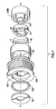
- FIG. 5 is a cut away cross section of the embodiment in FIG. 4 .
- FIG. 6 is a cut away perspective view of an alternate embodiment.
- FIG. 7 is a exploded view of the alternate embodiment in FIG. 6 .
- FIG. 8 is a perspective view of the alternate embodiment in FIG. 6 .
- FIG. 1 is a cut away perspective view of the isolator decoupler.
- the isolator decoupler eliminates belt slip due to engine deceleration and also filters out reverse vibration during engine start up/shut down.
- Isolator decoupler 100 comprises a compact design. The components of the isolator decoupler are contained within the pulley 50 . Wedge disk 10 is cooperatively engaged with wedge disk 20 . Wedge disk 20 is attached to a hub 30 .
- Wedge disk 10 comprises a plurality of tapered portions 11 which are disposed about the circumference of disk 10 .
- Each tapered portion 11 cooperatively engages a tapered portion 21 of wedge disk 20 .
- Each tapered portion extends along an axis of rotation A-A having an included angle ⁇ .
- the number of tapered portions 11 , 21 and the angle ⁇ of each tapered portion is selected based on the torque load requirements of the accessory drive and disengagement response time.
- Angle ⁇ is determined with reference to a normal plane which extends normal to an axis of rotation. Angle ⁇ is situated normal to the normal plane. The normal plane is substantially parallel to surface 13 .
- Springs 60 are disposed between each wedge disk 10 and wedge disk 20 .
- Springs 60 are used to resiliently maintain a predetermined relationship between wedge disk 10 and wedge disk 20 , namely, keeping wedge disk 10 in contact with isolator plate 40 .
- the spring shape or number of springs can be varied as well depending upon the operating requirements, for example using leaf springs, rubber members, coil springs and so on.
- Wedge disk 10 can comprise plastic material, or plastic combined with metal, or any other suitable molding material having like strength.
- Wedge disk 20 can comprise stamped sheet metal, cast iron, flow formed aluminum, plastic or similar material.
- Wedge surfaces 12 , 22 are in sliding contact with each other.
- Each wedge surface 12 , 22 comprise a very low coefficient of friction (COF) of less than approximately 0.2 to facilitate ease of relative movement.
- surface 13 is coated or molded with a high COF material in the range of approximately 0.5 to approximately 3.0.
- Surface 13 is made of a durable material such as metal or plastic.
- Wedge disk surface 13 is slidingly engaged with isolator plate 40 .
- a resilient spring member 70 Disposed between isolator plate 40 and pulley 50 is a resilient spring member 70 .
- Spring member 70 is attached to pulley 50 and isolator plate 40 .
- Spring member 70 comprises either natural rubber or synthetic polymers or a metal spring, each known in the art, or a combination of two or more of the foregoing. Spring member 70 isolates and absorbs crankshaft pulses that would otherwise be transmitted to the pulley and thereby to the belt driven accessories (not shown).
- Hub 30 is connected to an engine crankshaft (not shown) using fasteners such as bolts (not shown) through holes 31 .
- Hub 30 can be press fit to engage hub member 32 .
- wedge disk 10 On engine start-up as the crankshaft turns wedge disk 20 in the engine rotation direction wedge disk 10 is pushed toward isolator plate 40 by interaction of the tapered portions 11 , 21 . Wedge disk 10 drives pulley 50 through friction force imparted to the isolator plate 40 and thereby through elastomeric member 70 to pulley 50 . Pulley 50 then drives the engine accessory system through a belt engaged with surface 51 , see FIG. 2 .
- pulley 50 will be driven in the reverse direction by the momentum of the belt drive system through the belt.
- Wedge disk 10 and wedge disk 20 move axially toward each as tapered portions 11 , 21 slide together.
- Relative axial movement of wedge disk 10 with respect to wedge disk 20 causes surface 13 to disengage from isolator plate 40 , thereby temporarily disengaging the pulley from the crankshaft.
- This instantaneous reversal of torque flow direction allows the pulley to temporarily overrun the crankshaft rotation.
- Springs 60 allow for a soft engagement between wedge disk 10 and isolator plate 40 during reverse running or stop events.
- FIG. 2 is a front exploded view of the isolator in FIG. 11 .
- Wedge disk 20 is nested within hub 30 .
- Wedge disk 10 is cooperatively engaged with wedge disk 20 .
- Springs 60 are disposed at an end of each tapered portion 11 , 21 , between each wedge disk 10 , 20 .
- Hub member 32 is attached to hub 30 using fasteners 33 , or by other suitable means such as staking, welding or riveting.
- Rim 34 of member 32 captures pulley 50 , bushing 80 , elastomeric member 70 , isolator plate 40 , bushing 82 , wedge disk 20 , wedge disk 10 between member 32 and hub 30 .
- a low friction bushing 81 is disposed between member 32 and pulley 50 to hold alignment and to allow relative movement between them.
- Bushing 82 is disposed between pulley 50 and isolator plate 40 to hold alignment and to allow relative movement between them.
- Bushing 83 is disposed between isolator plate 40 and hub 30 to hold alignment and to allow relative movement between them.
- the bushings may comprise any low friction bushing or bearing suitable for the service.
- FIG. 3 is an exploded view of an alternate embodiment.
- the components in this alternate embodiment are as described for FIGS. 1 and 2 with the exception of springs 61 .
- each spring 61 comprises a coil spring which is compressed between the wedge disk 10 and wedge disk 20 during operation.
- Recesses 62 receive each spring 61 .
- FIG. 4 is an exploded view of yet another alternate embodiment.
- wedge disk 10 and wedge disk 20 are replaced with cooperating wedge circular portions 200 and 300 .
- Each wedge circular portion 200 , 300 has a tapered shape.
- Disposed between each wedge circular portion 200 , 300 is a spring 700 .
- Each spring 700 bears upon a portion 200 and urges each portion 300 into contact with a hub plate surface 403 .
- Each wedge portion comprises an angle ( ⁇ ). Angle ⁇ is situated parallel to a plane which extends normal to an axis of rotation A-A.
- Hub portion 320 is attached to hub 301 using fasteners 330 .
- Elastomeric member 402 is attached to pulley 500 and to hub plate 400 .
- Bushing 401 is disposed between hub plate 400 and hub portion 301 .
- Bushing 404 is disposed between hub portion 301 and pulley 500 .
- Bushings 601 , 602 and 603 are each low friction to allow relative movement between adjacent components.
- Each wedge surface 304 is coated or molded in with a high COF in the range of approximately 0.5 to approximately 3.0 and made of durable material such as metal or plastic.
- the number of wedge portions 200 , 300 and the angle ⁇ of each portion is selected based on the torque load requirements of the accessory drive and disengagement response time.
- the surface of each wedge portion 200 , 300 each have a coefficient of friction of less than approximately 0.2.
- Wedge circular portions 200 are fixedly attached to and/or form a part of hub 301 . Portions 300 are not attached to hub 301 . Each portion 300 “floats” between and is constrained by each adjacent portion 200 and surface 403 . With the wedge circular portions, a frictional driving force is generated between surface 304 of portion 300 and outer diameter surface 401 as a result of the relative movement (wedging) between portion 200 and portion 300 . As a result of movement of portion 200 with respect to portion 300 caused by rotation of hub 301 , portion 300 is pressed radially inward upon surface 403 of the isolator to transfer the torque from the hub 301 , through portions 300 to the isolator plate 400 . Torque is then transmitted through elastomeric member 402 and thereby to pulley 500 during normal, non-accelerating running condition. Pulley 500 drives a belt (not shown).
- wedge portion 300 moves relative to portion 200 to disengage portion 300 from the surface 403 . This releases the frictional force between portion 300 and surface 403 , thereby allowing isolator to decouple the belt from the crankshaft and thereby to overrun the crankshaft during deceleration (shut-down) or start up.
- FIG. 5 is a cut away cross section of the embodiment in FIG. 4 .
- Hub portion 301 is omitted from this figure for reasons of clarity.
- Spring member 501 holds each wedge portion 300 away from hub portion 301 . Since hub portion 301 has some small amount of relative movement with respect to the wedge members 300 , the spacing effect of spring member 501 prevents undue rubbing, wear, frictional heating and damping between wedge members 300 and hub portion 301 .
- FIG. 6 is a cut away perspective view of an alternate embodiment.
- the resilient spring member 70 is not used.
- the components in this alternate embodiment are as described in FIGS. 1 through 5 except as specifically provided for in this FIG. 6 .
- a low friction bushing 502 is disposed between flange 501 and pulley flange 503 .
- Flange 501 is fixedly connected to end 301 of hub 3000 , for example, by a press fit.
- Wedge disk 20 is fixedly engaged within hub 3000 .
- Wedge disk 20 does not rotate with respect to hub 3000 .
- Tapered portions 11 and wedge disk 20 operate as described in FIGS. 1 through 5 .
- Surface 13 of tapered portions 11 frictionally engage wedge disk 20 and flange 503 .
- Belt engaging surface 504 is for engaging a belt (not shown).
- FIG. 7 is an exploded view of the alternate embodiment in FIG. 6 .
- Hub 3000 is fixedly attached to a shaft, such as an alternator shaft (not shown).
- Wedge disk 20 rotates with hub 3000 .
- Wedge disk 10 and wedge disk 20 and tapered portions 11 operate as described for FIGS. 1-5 .
- FIG. 8 is a perspective view of the alternate embodiment in FIG. 6 .
- Notches 201 engage cooperating tabs 301 in hub 3000 , which assures that wedge disk 20 fixedly rotates with hub 3000 .
Abstract
Description
Claims (6)
Priority Applications (9)
| Application Number | Priority Date | Filing Date | Title |
|---|---|---|---|
| US11/977,637 US7891475B2 (en) | 2007-10-25 | 2007-10-25 | Isolator decoupler |
| RU2010120796/11A RU2442041C1 (en) | 2007-10-25 | 2008-10-17 | Isolating disconnector |
| CA2702818A CA2702818C (en) | 2007-10-25 | 2008-10-17 | Isolator decoupler |
| EP08842194A EP2203655B1 (en) | 2007-10-25 | 2008-10-17 | Isolator decoupler |
| JP2010531012A JP5337810B2 (en) | 2007-10-25 | 2008-10-17 | Isolator separator |
| KR1020107011183A KR101179317B1 (en) | 2007-10-25 | 2008-10-17 | Isolator decoupler |
| CN200880112963.3A CN101836004B (en) | 2007-10-25 | 2008-10-17 | Isolator decoupler |
| BRPI0817815 BRPI0817815A2 (en) | 2007-10-25 | 2008-10-17 | INSULATING DECAPLER |
| PCT/US2008/011896 WO2009054919A1 (en) | 2007-10-25 | 2008-10-17 | Isolator decoupler |
Applications Claiming Priority (1)
| Application Number | Priority Date | Filing Date | Title |
|---|---|---|---|
| US11/977,637 US7891475B2 (en) | 2007-10-25 | 2007-10-25 | Isolator decoupler |
Publications (2)
| Publication Number | Publication Date |
|---|---|
| US20090107791A1 US20090107791A1 (en) | 2009-04-30 |
| US7891475B2 true US7891475B2 (en) | 2011-02-22 |
Family
ID=40467291
Family Applications (1)
| Application Number | Title | Priority Date | Filing Date |
|---|---|---|---|
| US11/977,637 Expired - Fee Related US7891475B2 (en) | 2007-10-25 | 2007-10-25 | Isolator decoupler |
Country Status (9)
| Country | Link |
|---|---|
| US (1) | US7891475B2 (en) |
| EP (1) | EP2203655B1 (en) |
| JP (1) | JP5337810B2 (en) |
| KR (1) | KR101179317B1 (en) |
| CN (1) | CN101836004B (en) |
| BR (1) | BRPI0817815A2 (en) |
| CA (1) | CA2702818C (en) |
| RU (1) | RU2442041C1 (en) |
| WO (1) | WO2009054919A1 (en) |
Cited By (18)
| Publication number | Priority date | Publication date | Assignee | Title |
|---|---|---|---|---|
| US20100009796A1 (en) * | 2008-07-09 | 2010-01-14 | Fitz Frank A | Cam damped pulley for rotary devices |
| US20130237351A1 (en) * | 2010-11-09 | 2013-09-12 | Litens Automotive Partnership | Decoupler assembly having limited overrunning capability |
| US20130345004A1 (en) * | 2012-06-20 | 2013-12-26 | Dayco Ip Holdings, Llc | Accessory drive decoupler |
| USD733188S1 (en) * | 2014-03-14 | 2015-06-30 | MTD Propducts Inc | Dog clutch |
| US9239093B2 (en) | 2010-04-30 | 2016-01-19 | Hutchinson | Decoupling pulley |
| US20160040771A1 (en) * | 2014-08-08 | 2016-02-11 | The Gates Corporation | Isolating pulley |
| USD756417S1 (en) | 2014-03-14 | 2016-05-17 | Mtd Products Inc | Dog clutch |
| US9581233B2 (en) | 2014-06-09 | 2017-02-28 | Dayco Ip Holdings, Llc | Torsional vibration damper with an interlocked isolator |
| US9797498B2 (en) | 2013-05-23 | 2017-10-24 | Litens Automotive Partnership | Isolator with double acting spring system with reduced noise |
| US9850997B2 (en) | 2013-08-06 | 2017-12-26 | Dayco Europe S.R.L | Filtering pulley for a belt drive |
| US10030757B2 (en) | 2014-07-01 | 2018-07-24 | Dayco Ip Holdings, Llc | Torsional vibration damper with an interlocked isolator |
| US10041578B2 (en) | 2013-07-25 | 2018-08-07 | Litens Automotive Partnership | Spring assembly for isolator |
| US10060502B2 (en) | 2012-10-12 | 2018-08-28 | Litens Automotive Partnership | Isolator for use with engine that is assisted or started by an MGU or a motor through an endless drive member |
| US10125856B2 (en) | 2013-11-10 | 2018-11-13 | Litens Automotive Partnership | Isolator with dual springs |
| US20180328414A1 (en) * | 2015-12-08 | 2018-11-15 | Schaeffler Technologies AG & Co. KG | Belt pulley decoupler |
| US10267405B2 (en) | 2013-07-24 | 2019-04-23 | Litens Automotive Partnership | Isolator with improved damping structure |
| US20200141451A1 (en) * | 2017-05-22 | 2020-05-07 | Dayco Europe S.R.L. | Filtering pulley assembly for a belt drive |
| US10697531B2 (en) * | 2014-11-28 | 2020-06-30 | Vibracoustic Gmbh | Vibration damping device |
Families Citing this family (16)
| Publication number | Priority date | Publication date | Assignee | Title |
|---|---|---|---|---|
| US8292766B2 (en) * | 2010-05-14 | 2012-10-23 | Connard Cali | Overrunning isolating decoupler pulleys |
| DE102011086185A1 (en) | 2010-12-09 | 2012-06-14 | Schaeffler Technologies Gmbh & Co. Kg | Free-wheel device for belt pulley coupler utilized for attenuating torsional vibrations of e.g. crankshaft, of automobile engine, has ring formed such that rotational torque is transferred between flanges in transmission direction |
| US20120172163A1 (en) * | 2010-12-29 | 2012-07-05 | Fitz Frank A | Elastomeric spring pulley assembly for rotary devices |
| US20120322592A1 (en) * | 2011-04-11 | 2012-12-20 | Zen Sa Industria Metalurgica | Overrunning pulley with elastomer torsional damping system |
| US8734279B2 (en) * | 2011-06-08 | 2014-05-27 | Gates Corporation | Tensioner |
| US20130059685A1 (en) * | 2011-09-07 | 2013-03-07 | Connard Cali | Self-lubricating torque transfer devices |
| US9097335B2 (en) * | 2013-07-29 | 2015-08-04 | Gates Corporation | Crankshaft isolating decoupler |
| JP2015129543A (en) * | 2014-01-07 | 2015-07-16 | Nok株式会社 | Torque fluctuation absorbing damper |
| US9169914B2 (en) * | 2014-03-07 | 2015-10-27 | Gates Corporation | Isolating decoupler |
| DE102014223139A1 (en) * | 2014-11-13 | 2016-05-19 | Voith Patent Gmbh | torsional vibration damper |
| CN104791398A (en) * | 2015-02-04 | 2015-07-22 | 洪涛 | Space wedging type overrun belt pulley, overrun decoupler, crankshaft damping overrun belt pulley and torsional damping overrun clutch |
| FR3053394B1 (en) * | 2016-06-30 | 2019-08-09 | Hutchinson | DECOUPLING PULLEY WITH DEPARTURE CLUTCH |
| CN106641022A (en) * | 2016-12-23 | 2017-05-10 | 陕西国力信息技术有限公司 | Friction plate type peripheral spiral surface pressing overrunning clutch |
| WO2020181185A1 (en) * | 2019-03-07 | 2020-09-10 | Magna Exteriors Inc. | Active aerodynamics non-backdriveable clutch device |
| US11333223B2 (en) * | 2019-08-06 | 2022-05-17 | Gates Corporation | Orbital tensioner |
| DE102019217415A1 (en) * | 2019-11-12 | 2021-05-12 | Zf Friedrichshafen Ag | Hub arrangement, hybrid module with the hub arrangement and method for assembling the hub arrangement |
Citations (13)
| Publication number | Priority date | Publication date | Assignee | Title |
|---|---|---|---|---|
| US2398261A (en) * | 1941-11-24 | 1946-04-09 | Deister Concentrator Company | Flexible coupling |
| US3958679A (en) | 1974-11-04 | 1976-05-25 | The Garrett Corporation | Decoupler |
| US4204589A (en) | 1978-08-07 | 1980-05-27 | The United States Of America As Represented By The Secretary Of The Navy | Shaft decoupling device |
| US4753422A (en) | 1986-01-30 | 1988-06-28 | Thorn Richard P | Quiet acting low friction decouplers for fluid filled vibration isolators |
| US5722909A (en) | 1995-09-27 | 1998-03-03 | Litens Automotive Partnership | Series type decoupling device |
| US6044943A (en) | 1994-10-14 | 2000-04-04 | Litens Automotive Partnership | Shaft decoupler |
| US6059085A (en) | 1998-12-17 | 2000-05-09 | Alliedsignal Inc. | Shaft decoupler |
| EP1279807A1 (en) | 2001-07-26 | 2003-01-29 | Diantel Corporation N.V. | Pulley unit, in particular for an internal combustion engine |
| WO2004070225A1 (en) | 2003-02-04 | 2004-08-19 | Litens Automotive | Crankshaft torque modulator |
| US20060191519A1 (en) * | 2005-02-25 | 2006-08-31 | Bartell Ricky J | Apparatus for driving and braking a cutting blade of a lawn mower |
| US7153227B2 (en) | 2002-04-18 | 2006-12-26 | Litens Automotive | Isolator for alternator pulley |
| EP1754914A1 (en) | 2005-08-19 | 2007-02-21 | Industrias Cántabras de Torneado S.R.L. | Alternator pulley |
| US20070209899A1 (en) * | 2006-03-09 | 2007-09-13 | Keming Liu | Decoupling vibration isolator |
Family Cites Families (7)
| Publication number | Priority date | Publication date | Assignee | Title |
|---|---|---|---|---|
| JPS60131735U (en) * | 1984-02-13 | 1985-09-03 | 川崎重工業株式会社 | Shock absorber for power transmission mechanism |
| JP2001108068A (en) * | 1999-10-06 | 2001-04-20 | Mitsubishi Motors Corp | Damper pulley |
| JP2005233302A (en) * | 2004-02-19 | 2005-09-02 | Koyo Seiko Co Ltd | Power transmission device |
| JP2005249037A (en) * | 2004-03-03 | 2005-09-15 | Koyo Seiko Co Ltd | Power transmission device |
| JP2006009899A (en) * | 2004-06-24 | 2006-01-12 | Koyo Seiko Co Ltd | Power transmission |
| DE102004035969C5 (en) * | 2004-07-23 | 2019-06-19 | Vibracoustic Gmbh | Decoupled pulley |
| JP2006038183A (en) * | 2004-07-30 | 2006-02-09 | Koyo Seiko Co Ltd | Power transmission |
-
2007
- 2007-10-25 US US11/977,637 patent/US7891475B2/en not_active Expired - Fee Related
-
2008
- 2008-10-17 RU RU2010120796/11A patent/RU2442041C1/en not_active IP Right Cessation
- 2008-10-17 JP JP2010531012A patent/JP5337810B2/en not_active Expired - Fee Related
- 2008-10-17 EP EP08842194A patent/EP2203655B1/en not_active Not-in-force
- 2008-10-17 KR KR1020107011183A patent/KR101179317B1/en active IP Right Grant
- 2008-10-17 CN CN200880112963.3A patent/CN101836004B/en not_active Expired - Fee Related
- 2008-10-17 WO PCT/US2008/011896 patent/WO2009054919A1/en active Application Filing
- 2008-10-17 CA CA2702818A patent/CA2702818C/en not_active Expired - Fee Related
- 2008-10-17 BR BRPI0817815 patent/BRPI0817815A2/en not_active IP Right Cessation
Patent Citations (14)
| Publication number | Priority date | Publication date | Assignee | Title |
|---|---|---|---|---|
| US2398261A (en) * | 1941-11-24 | 1946-04-09 | Deister Concentrator Company | Flexible coupling |
| US3958679A (en) | 1974-11-04 | 1976-05-25 | The Garrett Corporation | Decoupler |
| US4204589A (en) | 1978-08-07 | 1980-05-27 | The United States Of America As Represented By The Secretary Of The Navy | Shaft decoupling device |
| US4753422A (en) | 1986-01-30 | 1988-06-28 | Thorn Richard P | Quiet acting low friction decouplers for fluid filled vibration isolators |
| US6044943A (en) | 1994-10-14 | 2000-04-04 | Litens Automotive Partnership | Shaft decoupler |
| US5722909A (en) | 1995-09-27 | 1998-03-03 | Litens Automotive Partnership | Series type decoupling device |
| US6059085A (en) | 1998-12-17 | 2000-05-09 | Alliedsignal Inc. | Shaft decoupler |
| EP1279807A1 (en) | 2001-07-26 | 2003-01-29 | Diantel Corporation N.V. | Pulley unit, in particular for an internal combustion engine |
| US7153227B2 (en) | 2002-04-18 | 2006-12-26 | Litens Automotive | Isolator for alternator pulley |
| US7207910B2 (en) | 2002-04-18 | 2007-04-24 | Litens Automotive | Isolator for alternator pulley |
| WO2004070225A1 (en) | 2003-02-04 | 2004-08-19 | Litens Automotive | Crankshaft torque modulator |
| US20060191519A1 (en) * | 2005-02-25 | 2006-08-31 | Bartell Ricky J | Apparatus for driving and braking a cutting blade of a lawn mower |
| EP1754914A1 (en) | 2005-08-19 | 2007-02-21 | Industrias Cántabras de Torneado S.R.L. | Alternator pulley |
| US20070209899A1 (en) * | 2006-03-09 | 2007-09-13 | Keming Liu | Decoupling vibration isolator |
Cited By (27)
| Publication number | Priority date | Publication date | Assignee | Title |
|---|---|---|---|---|
| US8272982B2 (en) * | 2008-07-09 | 2012-09-25 | Ct Drives, Llc | Cam damped pulley for rotary devices |
| US20100009796A1 (en) * | 2008-07-09 | 2010-01-14 | Fitz Frank A | Cam damped pulley for rotary devices |
| US9239093B2 (en) | 2010-04-30 | 2016-01-19 | Hutchinson | Decoupling pulley |
| US9518646B2 (en) * | 2010-11-09 | 2016-12-13 | Litens Automotive Partnership | Decoupler assembly having limited overrunning capability |
| US20150226309A1 (en) * | 2010-11-09 | 2015-08-13 | Litens Automotive Partnership | Decoupler assembly having limited overrunning capability |
| US9046133B2 (en) * | 2010-11-09 | 2015-06-02 | Litens Automotive Partnership | Decoupler assembly having limited overrunning capability |
| US20130237351A1 (en) * | 2010-11-09 | 2013-09-12 | Litens Automotive Partnership | Decoupler assembly having limited overrunning capability |
| US20130345004A1 (en) * | 2012-06-20 | 2013-12-26 | Dayco Ip Holdings, Llc | Accessory drive decoupler |
| US10060502B2 (en) | 2012-10-12 | 2018-08-28 | Litens Automotive Partnership | Isolator for use with engine that is assisted or started by an MGU or a motor through an endless drive member |
| US9797498B2 (en) | 2013-05-23 | 2017-10-24 | Litens Automotive Partnership | Isolator with double acting spring system with reduced noise |
| US10690228B2 (en) | 2013-05-23 | 2020-06-23 | Litens Automotive Partnership | Isolator with double acting spring system with reduced noise |
| US10267405B2 (en) | 2013-07-24 | 2019-04-23 | Litens Automotive Partnership | Isolator with improved damping structure |
| US10041578B2 (en) | 2013-07-25 | 2018-08-07 | Litens Automotive Partnership | Spring assembly for isolator |
| US9850997B2 (en) | 2013-08-06 | 2017-12-26 | Dayco Europe S.R.L | Filtering pulley for a belt drive |
| US10125856B2 (en) | 2013-11-10 | 2018-11-13 | Litens Automotive Partnership | Isolator with dual springs |
| USD756417S1 (en) | 2014-03-14 | 2016-05-17 | Mtd Products Inc | Dog clutch |
| USD756418S1 (en) | 2014-03-14 | 2016-05-17 | Mtd Products Inc | Dog clutch |
| USD733188S1 (en) * | 2014-03-14 | 2015-06-30 | MTD Propducts Inc | Dog clutch |
| US9581233B2 (en) | 2014-06-09 | 2017-02-28 | Dayco Ip Holdings, Llc | Torsional vibration damper with an interlocked isolator |
| US10030757B2 (en) | 2014-07-01 | 2018-07-24 | Dayco Ip Holdings, Llc | Torsional vibration damper with an interlocked isolator |
| US9341254B2 (en) * | 2014-08-08 | 2016-05-17 | Gates Corporation | Isolating pulley |
| US20160040771A1 (en) * | 2014-08-08 | 2016-02-11 | The Gates Corporation | Isolating pulley |
| US10697531B2 (en) * | 2014-11-28 | 2020-06-30 | Vibracoustic Gmbh | Vibration damping device |
| US20180328414A1 (en) * | 2015-12-08 | 2018-11-15 | Schaeffler Technologies AG & Co. KG | Belt pulley decoupler |
| US10816041B2 (en) * | 2015-12-08 | 2020-10-27 | Schaeffler Technologies AG & Co. KG | Belt pulley decoupler |
| US20200141451A1 (en) * | 2017-05-22 | 2020-05-07 | Dayco Europe S.R.L. | Filtering pulley assembly for a belt drive |
| US11585390B2 (en) * | 2017-05-22 | 2023-02-21 | Dayco Europe S.R.L. | Filtering pulley assembly for a belt drive |
Also Published As
| Publication number | Publication date |
|---|---|
| CN101836004B (en) | 2014-02-26 |
| RU2442041C1 (en) | 2012-02-10 |
| KR101179317B1 (en) | 2012-09-03 |
| EP2203655B1 (en) | 2012-10-03 |
| CN101836004A (en) | 2010-09-15 |
| CA2702818C (en) | 2013-10-01 |
| CA2702818A1 (en) | 2009-04-30 |
| EP2203655A1 (en) | 2010-07-07 |
| WO2009054919A1 (en) | 2009-04-30 |
| US20090107791A1 (en) | 2009-04-30 |
| JP2011501077A (en) | 2011-01-06 |
| BRPI0817815A2 (en) | 2015-03-31 |
| RU2010120796A (en) | 2011-12-10 |
| JP5337810B2 (en) | 2013-11-06 |
| KR20100083178A (en) | 2010-07-21 |
Similar Documents
| Publication | Publication Date | Title |
|---|---|---|
| US7891475B2 (en) | Isolator decoupler | |
| CA2717376C (en) | Decoupling isolator | |
| US9328816B2 (en) | Isolator decoupler | |
| KR100413161B1 (en) | Crankshaft union | |
| KR101558117B1 (en) | Alternator isolating decoupler | |
| US8506434B2 (en) | Isolating decoupler | |
| US20080207364A1 (en) | Driving pulley with vibration damping means | |
| WO2012162280A1 (en) | Isolator decoupler |
Legal Events
| Date | Code | Title | Description |
|---|---|---|---|
| AS | Assignment |
Owner name: GATES CORPORATION, THE, COLORADO Free format text: ASSIGNMENT OF ASSIGNORS INTEREST;ASSIGNORS:ZHU, LIN;CADARETTE, MARC R.;HODJAT, YAHYA;REEL/FRAME:020329/0829;SIGNING DATES FROM 20071018 TO 20071019 |
|
| AS | Assignment |
Owner name: CITICORP USA, INC., AS COLLATERAL AGENT, NEW YORK Free format text: SECURITY AGREEMENT;ASSIGNORS:AIR SYSTEM COMPONENTS, INC.;AQUATIC CO.;DEXTER AXLE COMPANY;AND OTHERS;REEL/FRAME:025549/0407 Effective date: 20100929 |
|
| AS | Assignment |
Owner name: WILMINGTON TRUST FSB, AS COLLATERAL AGENT, CONNECT Free format text: SECOND LIEN NOTES PATENT SECURITY AGREEMENT;ASSIGNORS:AIR SYSTEM COMPONENTS, INC.;AQUATIC CO.;DEXTER AXLE COMPANY;AND OTHERS;REEL/FRAME:025560/0057 Effective date: 20100929 |
|
| STCF | Information on status: patent grant |
Free format text: PATENTED CASE |
|
| AS | Assignment |
Owner name: GATES MECTROL, INC., A DELAWARE CORPORATION, NEW H Free format text: RELEASE OF SECURITY AGREEMENT;ASSIGNOR:WILMINGTON TRUST, NATIONAL ASSOCIATION;REEL/FRAME:033290/0631 Effective date: 20140703 Owner name: THE GATES CORPORATION, A DELAWARE CORPORATION, COL Free format text: RELEASE OF SECURITY AGREEMENT;ASSIGNOR:WILMINGTON TRUST, NATIONAL ASSOCIATION;REEL/FRAME:033290/0631 Effective date: 20140703 Owner name: AQUATIC CO., CALIFORNIA Free format text: RELEASE OF SECURITY AGREEMENT;ASSIGNOR:WILMINGTON TRUST, NATIONAL ASSOCIATION;REEL/FRAME:033290/0631 Effective date: 20140703 Owner name: EIFELER MASCHINENBAU GMBH, GERMANY Free format text: RELEASE OF SECURITY AGREEMENT;ASSIGNOR:WILMINGTON TRUST, NATIONAL ASSOCIATION;REEL/FRAME:033290/0631 Effective date: 20140703 Owner name: AQUATIC CO., CALIFORNIA Free format text: RELEASE OF SECURITY AGREEMENT;ASSIGNOR:CITICORP USA, INC.;REEL/FRAME:033289/0254 Effective date: 20140703 Owner name: GATES MECTROL, INC., A DELAWARE CORPORATION, NEW H Free format text: RELEASE OF SECURITY AGREEMENT;ASSIGNOR:CITICORP USA, INC.;REEL/FRAME:033289/0254 Effective date: 20140703 Owner name: THE GATES CORPORATION, A DELAWARE CORPORATION, COL Free format text: RELEASE OF SECURITY AGREEMENT;ASSIGNOR:CITICORP USA, INC.;REEL/FRAME:033289/0254 Effective date: 20140703 Owner name: EIFELER MASCHINENBAU GMBH, GERMANY Free format text: RELEASE OF SECURITY AGREEMENT;ASSIGNOR:CITICORP USA, INC.;REEL/FRAME:033289/0254 Effective date: 20140703 |
|
| AS | Assignment |
Owner name: CREDIT SUISSE AG, CAYMAN ISLANDS BRANCH, AS COLLAT Free format text: SECURITY INTEREST;ASSIGNOR:THE GATES CORPORATION;REEL/FRAME:033465/0252 Effective date: 20140801 |
|
| AS | Assignment |
Owner name: CITIBANK, N.A., AS COLLATERAL AGENT, NEW YORK Free format text: SECURITY INTEREST;ASSIGNOR:THE GATES CORPORATION;REEL/FRAME:033472/0333 Effective date: 20140804 |
|
| FPAY | Fee payment |
Year of fee payment: 4 |
|
| AS | Assignment |
Owner name: GATES CORPORATION, COLORADO Free format text: CHANGE OF NAME;ASSIGNOR:THE GATES CORPORATION;REEL/FRAME:034893/0006 Effective date: 20150108 |
|
| FEPP | Fee payment procedure |
Free format text: MAINTENANCE FEE REMINDER MAILED (ORIGINAL EVENT CODE: REM.); ENTITY STATUS OF PATENT OWNER: LARGE ENTITY |
|
| LAPS | Lapse for failure to pay maintenance fees |
Free format text: PATENT EXPIRED FOR FAILURE TO PAY MAINTENANCE FEES (ORIGINAL EVENT CODE: EXP.); ENTITY STATUS OF PATENT OWNER: LARGE ENTITY |
|
| STCH | Information on status: patent discontinuation |
Free format text: PATENT EXPIRED DUE TO NONPAYMENT OF MAINTENANCE FEES UNDER 37 CFR 1.362 |
|
| FP | Lapsed due to failure to pay maintenance fee |
Effective date: 20190222 |