US7890217B2 - Integrated real-time power and solar farm control system - Google Patents
Integrated real-time power and solar farm control system Download PDFInfo
- Publication number
- US7890217B2 US7890217B2 US12/606,134 US60613409A US7890217B2 US 7890217 B2 US7890217 B2 US 7890217B2 US 60613409 A US60613409 A US 60613409A US 7890217 B2 US7890217 B2 US 7890217B2
- Authority
- US
- United States
- Prior art keywords
- power
- farm
- real
- renewable energy
- control
- Prior art date
- Legal status (The legal status is an assumption and is not a legal conclusion. Google has not performed a legal analysis and makes no representation as to the accuracy of the status listed.)
- Active
Links
Images


Classifications
-
- H—ELECTRICITY
- H02—GENERATION; CONVERSION OR DISTRIBUTION OF ELECTRIC POWER
- H02J—ELECTRIC POWER NETWORKS; CIRCUIT ARRANGEMENTS OR SYSTEMS FOR SUPPLYING OR DISTRIBUTING ELECTRIC POWER; SYSTEMS FOR STORING ELECTRIC ENERGY
- H02J13/00—Circuit arrangements for providing remote monitoring or remote control of equipment in a power distribution network
- H02J13/12—Monitoring network conditions, e.g. electrical magnitudes or operational status
-
- H—ELECTRICITY
- H02—GENERATION; CONVERSION OR DISTRIBUTION OF ELECTRIC POWER
- H02J—ELECTRIC POWER NETWORKS; CIRCUIT ARRANGEMENTS OR SYSTEMS FOR SUPPLYING OR DISTRIBUTING ELECTRIC POWER; SYSTEMS FOR STORING ELECTRIC ENERGY
- H02J13/00—Circuit arrangements for providing remote monitoring or remote control of equipment in a power distribution network
- H02J13/18—Circuit arrangements for providing remote monitoring or remote control of equipment in a power distribution network characterised by the remotely-controlled equipment, e.g. converters or transformers
- H02J13/333—Circuit arrangements for providing remote monitoring or remote control of equipment in a power distribution network characterised by the remotely-controlled equipment, e.g. converters or transformers the equipment forming part of substations
-
- H—ELECTRICITY
- H02—GENERATION; CONVERSION OR DISTRIBUTION OF ELECTRIC POWER
- H02J—ELECTRIC POWER NETWORKS; CIRCUIT ARRANGEMENTS OR SYSTEMS FOR SUPPLYING OR DISTRIBUTING ELECTRIC POWER; SYSTEMS FOR STORING ELECTRIC ENERGY
- H02J3/00—Circuit arrangements for AC mains or AC distribution networks
- H02J3/38—Arrangements for feeding a single network from two or more generators or sources in parallel; Arrangements for feeding already energised networks from additional generators or sources in parallel
- H02J3/381—Dispersed generators
-
- H—ELECTRICITY
- H02—GENERATION; CONVERSION OR DISTRIBUTION OF ELECTRIC POWER
- H02J—ELECTRIC POWER NETWORKS; CIRCUIT ARRANGEMENTS OR SYSTEMS FOR SUPPLYING OR DISTRIBUTING ELECTRIC POWER; SYSTEMS FOR STORING ELECTRIC ENERGY
- H02J3/00—Circuit arrangements for AC mains or AC distribution networks
- H02J3/38—Arrangements for feeding a single network from two or more generators or sources in parallel; Arrangements for feeding already energised networks from additional generators or sources in parallel
- H02J3/46—Controlling the sharing of generated power between the generators, sources or networks
-
- H—ELECTRICITY
- H02—GENERATION; CONVERSION OR DISTRIBUTION OF ELECTRIC POWER
- H02J—ELECTRIC POWER NETWORKS; CIRCUIT ARRANGEMENTS OR SYSTEMS FOR SUPPLYING OR DISTRIBUTING ELECTRIC POWER; SYSTEMS FOR STORING ELECTRIC ENERGY
- H02J2101/00—Supply or distribution of decentralised, dispersed or local electric power generation
- H02J2101/20—Dispersed power generation using renewable energy sources
- H02J2101/22—Solar energy
- H02J2101/24—Photovoltaics
-
- Y—GENERAL TAGGING OF NEW TECHNOLOGICAL DEVELOPMENTS; GENERAL TAGGING OF CROSS-SECTIONAL TECHNOLOGIES SPANNING OVER SEVERAL SECTIONS OF THE IPC; TECHNICAL SUBJECTS COVERED BY FORMER USPC CROSS-REFERENCE ART COLLECTIONS [XRACs] AND DIGESTS
- Y02—TECHNOLOGIES OR APPLICATIONS FOR MITIGATION OR ADAPTATION AGAINST CLIMATE CHANGE
- Y02E—REDUCTION OF GREENHOUSE GAS [GHG] EMISSIONS, RELATED TO ENERGY GENERATION, TRANSMISSION OR DISTRIBUTION
- Y02E10/00—Energy generation through renewable energy sources
- Y02E10/40—Solar thermal energy, e.g. solar towers
- Y02E10/46—Conversion of thermal power into mechanical power, e.g. Rankine, Stirling or solar thermal engines
-
- Y—GENERAL TAGGING OF NEW TECHNOLOGICAL DEVELOPMENTS; GENERAL TAGGING OF CROSS-SECTIONAL TECHNOLOGIES SPANNING OVER SEVERAL SECTIONS OF THE IPC; TECHNICAL SUBJECTS COVERED BY FORMER USPC CROSS-REFERENCE ART COLLECTIONS [XRACs] AND DIGESTS
- Y02—TECHNOLOGIES OR APPLICATIONS FOR MITIGATION OR ADAPTATION AGAINST CLIMATE CHANGE
- Y02E—REDUCTION OF GREENHOUSE GAS [GHG] EMISSIONS, RELATED TO ENERGY GENERATION, TRANSMISSION OR DISTRIBUTION
- Y02E10/00—Energy generation through renewable energy sources
- Y02E10/50—Photovoltaic [PV] energy
- Y02E10/56—Power conversion systems, e.g. maximum power point trackers
-
- Y—GENERAL TAGGING OF NEW TECHNOLOGICAL DEVELOPMENTS; GENERAL TAGGING OF CROSS-SECTIONAL TECHNOLOGIES SPANNING OVER SEVERAL SECTIONS OF THE IPC; TECHNICAL SUBJECTS COVERED BY FORMER USPC CROSS-REFERENCE ART COLLECTIONS [XRACs] AND DIGESTS
- Y02—TECHNOLOGIES OR APPLICATIONS FOR MITIGATION OR ADAPTATION AGAINST CLIMATE CHANGE
- Y02E—REDUCTION OF GREENHOUSE GAS [GHG] EMISSIONS, RELATED TO ENERGY GENERATION, TRANSMISSION OR DISTRIBUTION
- Y02E40/00—Technologies for an efficient electrical power generation, transmission or distribution
- Y02E40/70—Smart grids as climate change mitigation technology in the energy generation sector
-
- Y—GENERAL TAGGING OF NEW TECHNOLOGICAL DEVELOPMENTS; GENERAL TAGGING OF CROSS-SECTIONAL TECHNOLOGIES SPANNING OVER SEVERAL SECTIONS OF THE IPC; TECHNICAL SUBJECTS COVERED BY FORMER USPC CROSS-REFERENCE ART COLLECTIONS [XRACs] AND DIGESTS
- Y02—TECHNOLOGIES OR APPLICATIONS FOR MITIGATION OR ADAPTATION AGAINST CLIMATE CHANGE
- Y02E—REDUCTION OF GREENHOUSE GAS [GHG] EMISSIONS, RELATED TO ENERGY GENERATION, TRANSMISSION OR DISTRIBUTION
- Y02E60/00—Enabling technologies; Technologies with a potential or indirect contribution to GHG emissions mitigation
-
- Y—GENERAL TAGGING OF NEW TECHNOLOGICAL DEVELOPMENTS; GENERAL TAGGING OF CROSS-SECTIONAL TECHNOLOGIES SPANNING OVER SEVERAL SECTIONS OF THE IPC; TECHNICAL SUBJECTS COVERED BY FORMER USPC CROSS-REFERENCE ART COLLECTIONS [XRACs] AND DIGESTS
- Y04—INFORMATION OR COMMUNICATION TECHNOLOGIES HAVING AN IMPACT ON OTHER TECHNOLOGY AREAS
- Y04S—SYSTEMS INTEGRATING TECHNOLOGIES RELATED TO POWER NETWORK OPERATION, COMMUNICATION OR INFORMATION TECHNOLOGIES FOR IMPROVING THE ELECTRICAL POWER GENERATION, TRANSMISSION, DISTRIBUTION, MANAGEMENT OR USAGE, i.e. SMART GRIDS
- Y04S10/00—Systems supporting electrical power generation, transmission or distribution
- Y04S10/12—Monitoring or controlling equipment for energy generation units, e.g. distributed energy generation [DER] or load-side generation
- Y04S10/123—Monitoring or controlling equipment for energy generation units, e.g. distributed energy generation [DER] or load-side generation the energy generation units being or involving renewable energy sources
-
- Y—GENERAL TAGGING OF NEW TECHNOLOGICAL DEVELOPMENTS; GENERAL TAGGING OF CROSS-SECTIONAL TECHNOLOGIES SPANNING OVER SEVERAL SECTIONS OF THE IPC; TECHNICAL SUBJECTS COVERED BY FORMER USPC CROSS-REFERENCE ART COLLECTIONS [XRACs] AND DIGESTS
- Y04—INFORMATION OR COMMUNICATION TECHNOLOGIES HAVING AN IMPACT ON OTHER TECHNOLOGY AREAS
- Y04S—SYSTEMS INTEGRATING TECHNOLOGIES RELATED TO POWER NETWORK OPERATION, COMMUNICATION OR INFORMATION TECHNOLOGIES FOR IMPROVING THE ELECTRICAL POWER GENERATION, TRANSMISSION, DISTRIBUTION, MANAGEMENT OR USAGE, i.e. SMART GRIDS
- Y04S10/00—Systems supporting electrical power generation, transmission or distribution
- Y04S10/30—State monitoring, e.g. fault, temperature monitoring, insulator monitoring, corona discharge
Definitions
- This invention generally relates to renewable energy sources, and more particularly, to systems and methods for controlling power in renewable solar energy sources.
- Solar farms are generally categorized as renewable variable power generation systems because the energy is harvested from sunlight: a naturally occurring and plentiful source of energy. However, the amount of power produced by the solar farm may vary as a function of cloud coverage and the position of the sun in the sky.
- Each solar farm may have a plurality of energy harvesting panels with associated photovoltaic cells and inverters that may require power monitoring and control for coordinating and providing power to the electrical grid. For example, a utility may monitor the grid power demand and may need to communicate with the solar farm to determine if the solar farm has the capacity to meet some or all of the power demand.
- Certain embodiments of the invention may include systems and methods for controlling power in renewable solar energy sources, for instance, integrated real-time power and solar farm control.
- a method is provided for controlling a renewable energy solar farm, where the farm may include one or more renewable energy sources.
- the method may include measuring aggregate energy output of the renewable energy solar farm and measuring individual source energy output of the one or more renewable energy sources.
- the method may also include controlling energy production from the one or more renewable energy sources via a controller based at least in part on the measured aggregate energy output and the measured individual source energy output, where the controller facilitates communications with the one or more renewable energy sources.
- a system for providing renewable solar energy.
- the system may include a solar energy farm including one or more renewable energy sources, one or more remote monitoring and control stations, one or more devices for measuring aggregate energy output from the solar energy farm, one or more devices for measuring individual source energy output from the one or more renewable energy sources, and a real-time controller for controlling power production of the one or more renewable energy sources based at least in part on the measured aggregate energy output and the measured individual source energy output, where the controller is operable to communicate with the one or more renewable energy sources.
- an apparatus for controlling renewable energy.
- the apparatus may include a real time integrated controller operable to: measure aggregate energy output from a solar energy farm, where the solar energy farm comprises one or more renewable energy sources, measure individual source energy output from the one or more renewable energy sources, control energy production from the one or more renewable energy sources based at least in part on the measured aggregate energy output and the measured individual source energy output, and communicate with the one or more renewable energy sources.
- FIG. 1 is a block diagram of an illustrative energy farm control system, according to an exemplary embodiment of the invention.
- FIG. 2 is a block diagram of an illustrative example integrated energy farm voltage regulator, according to an exemplary embodiment of the invention.
- FIG. 3 is a block diagram of an illustrative example active or apparent power regulator, according to an exemplary embodiment of the invention.
- FIG. 4 is a flow diagram of an example method for controlling power, according to an exemplary embodiment of the invention.
- FIG. 5 is an example chart indicating a frequency control curve, according to an exemplary embodiment of the invention.
- Certain embodiments of the invention may enable control of power in renewable solar energy farms.
- a real-time integrated controller may be utilized to facilitate increased interoperability and control within the renewable solar farm.
- Other embodiments may be utilized to facilitate increased interoperability and control among multiple farms.
- FIG. 1 illustrates an exemplary block diagram of an energy farm control system 100 .
- the system 100 may include a real-time integrated controller 102 .
- the system 100 may also include other associated elements 103 in communication with the real-time integrated controller 102 , including a plurality of communication channels 128 , 140 , renewable energy sources 130 , sensors, power monitors 138 , 142 , weather sensors 146 , substations 150 , and remote monitoring and control stations 148 .
- the real-time integrated controller 102 may communicate with, control, be controlled by, and/or coordinate the various functions associated with the other elements 103 associated with the system 100 .
- the real-time integrated controller 102 may include one or more processors 108 .
- the real-time integrated controller 102 may include a memory 104 , input/output (I/O) interfaces 110 , and network interfaces 112 , each in communication with the one or mores processors.
- the memory 104 may comprise an operating system (OS) 114 and a region for data 116 .
- OS operating system
- a number of modules may reside in the memory 104 for controlling the various functions associated with the real-time integrated controller 102 .
- the memory may include a farm control module 118 that may be operable to provide one or more of the following: voltage regulation, reactive power regulation, real power regulation, ramp rate control, startup control, shutdown control, voltage droop compensation, frequency droop compensation, line drop compensation and metering.
- a farm control module 118 may be operable to provide one or more of the following: voltage regulation, reactive power regulation, real power regulation, ramp rate control, startup control, shutdown control, voltage droop compensation, frequency droop compensation, line drop compensation and metering.
- the memory 104 of the real-time integrated controller 102 may also support other modules for coordinating with other elements 103 , including diagnostics 120 , sequencing/restoration 122 , plug and play 124 operations, and auto discovery 126 .
- the auto discovery 126 module may work in conjunction with the plug and play 124 module for interfacing with other elements 103 .
- the I/O interfaces 110 are operable to provide analog or digital communications.
- the analog communication channels may include scaling, limiting, polarity reversal, and/or filtering functions for conditioning input and output analog signals via the I/O interface 110 .
- the digital communication channels may include scalable provisioning of bit depth, communication rates, and/or sample rates to facilitate flexible communications and protocols.
- the real-time integrated controller 102 may be in communication with one or more remote monitoring and control stations 148 via the I/O interface 110 , network interface 112 , or via wireless communication, power line carrier, internet, intranet, or any other suitable means of communication.
- the remote monitoring and control station 148 may be operable, among other functions, to provide setpoints for use by the farm control module 118 , to control startup/shutdown, to communicate with any of the other elements 103 in communication with the real-time integrated controller 102 , and to receive monitoring information.
- weather sensors 146 may provide information to the real-time integrated controller 102 .
- the weather sensors 146 may be local to, or remote from the renewable energy sources 130 , and may provide information including temperature, humidity, barometric pressure, wind speed, expected cloud coverage, etc., to the real time integrated controller 102 .
- renewable energy sources 130 may be in communication with the real-time integrated controller 102 .
- the renewable energy sources 130 may include solar power harvesting devices, including photovoltaic cells, inverters such as 134 , and/or solar concentrators.
- the renewable energy sources 130 may also include energy storage devices such as 132 , including batteries, capacitors, and/or thermal storage devices.
- the individual source energy output 136 from the renewable energy sources 130 may be monitored by power monitor 138 , and the individual monitor signals may be communicated to the real-time integrated controller 102 for feedback and control.
- the real-time integrated controller 102 may provide control signals to the renewable energy sources 130 via one or two-way communications 128 , and may adjust the various parameters of the renewable energy sources 130 in accordance with the individual source monitoring/feedback signals 140 , and in response to requirements of the grid 158 .
- the aggregate energy output 156 of the farm may also be monitored by a power monitor 142 to provide aggregate monitoring/metering signals 144 that may also be used as feedback to the controller 102 for controlling the individual and/or collective power output from the renewable energy sources 130 .
- the real-time integrated controller 102 may be in communication with one or more substations 150 .
- the substations may include one or more VAR banks 152 and/or one or more transformer load tap changers 154 .
- the aggregate monitoring/metering signals 144 may be communicated to the substation 150 , and according to an exemplary embodiment, the substation 150 may monitor its own output via the substation output monitoring signal 145 .
- Processed or unprocessed monitoring signals 144 , 145 may be communicated to the real-time integrated controller 102 , and control signals may, in turn, be communicated back to the substation 150 for controlling the VAR banks 152 and/or tap changers 154 .
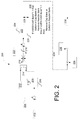
- FIG. 2 depicts an example integrated energy farm voltage regulator 200 with VAR bank control and hysteresis, according to an exemplary embodiment of the invention.
- the regulator 200 may determine and provide a power setpoint command 238 for each inverter, based on input setpoints ( 202 , 212 ), farm, grid, or inverter measurements ( 204 , 220 , 236 ), and inverter ratings ( 224 , 226 , 234 ).
- the input setpoints may be provided to the farm control module 118 ( FIG. 1 ) via I/O interfaces 110 or network interfaces 112 . According to exemplary embodiments, the input setpoints may be provided by the remote monitoring and control stations 148 .
- the farm, grid, or inverter measurements may be provided by the individual source monitoring 138 , aggregate monitoring 142 , and/or substation output monitoring 145 .
- the integrated energy farm voltage regulator 200 may also be operable to determine and provide VAR bank commands for the substation 150 , based at least upon a determined net VAR command 228 signal.
- the example integrated energy farm voltage regulator 200 may receive a power factor (or VAR) setpoint 202 as an input.
- Measured grid power factor (or VARs) 204 may be subtracted from the power factor (or VAR) setpoint 202 and the resulting signal may be input to a first PI regulator 208 .
- the PI regulator 208 may include an apparent power limiter 206 , and may have an optional reactive power (Q) reference input with real power (P) priority control.
- the first PI regulator 208 may include a voltage limiter 210 .
- the integrated energy farm voltage regulator 200 may be configured to regulate based either on power factor (or VAR) setpoint 202 or voltage setpoint 212 inputs. Switch 214 may be utilized to select the mode of regulation.
- the selected regulation setpoint signal (i.e., either the voltage setpoint 212 or the signal derived from the PI regulated power factor (or VAR) setpoint 202 ) may be further processed by a voltage limiter 216 and/or a slew rate limiter 218 .
- a measured grid voltage 220 may be subtracted from the output of the slew rate limiter 218 , and the result may be input to a second PI regulator 222 .
- the second PI regulator 222 may include a Q-min 226 limiter that may limit the net VAR command 228 signal to a minimum value about equal to the sum of the inverters 134 negative VAR capability.
- the second PI regulator 222 may also include a Q-max 224 limiter that may limit the net VAR command 228 signal to a maximum value about equal to the sum of the inverters 134 positive VAR capability.
- the second PI regulator 222 may produce a net VAR command 228 , and this command may be utilized by VAR bank switching logic 230 to control the substation 150 via substation commands 151 to switch VAR banks 152 in or out, depending on a comparison of the net VAR command 228 and the measured VARs, which in accordance with an exemplary embodiment, may be communicated to the regulator 200 via a substation output monitoring 145 signal.
- VAR bank switching logic 230 An exemplary embodiment of the VAR bank switching logic 230 is depicted in FIG. 2 .
- the VAR command 228 may be converted to power setpoints 238 for individual (N) inverters 134 by multiplying the VAR command 228 by the inverter (N) reactive power rating 234 and dividing by the farm reactive power 236 .
- the individual power setpoints 238 may then be communicated to the individual inverters 134 associated with each renewable energy source 130 .
- FIG. 3 depicts another example power regulator 300 system that can be utilized to regulate the power output of individual or collective renewable energy sources 130 .
- power regulation may be based on an input apparent power setpoint 306 or on an active power setpoint 302 , unlike the example integrated energy farm voltage regulator 200 system as shown in FIG. 2 , which may regulate based on a power factor (or VAR setpoint) 202 or on a voltage setpoint 212 .
- the example active (or apparent) power regulator 300 may utilize an active/apparent power mode select 310 input to select, via a mode select switch 308 , between either an active power setpoint 302 or an apparent power setpoint 306 .
- the apparent power setpoint 306 input may be converted to an active power value via an S to P converter 304 before reaching the mode select switch 308 .
- the selected input setpoint may be limited by a rated power limiter 312 to limit the maximum power to the rated power of the farm.
- the output of the rated power limiter 312 may be further processed by a ramp limiter 314 , which may limit the slew rate or ramp rate of the control signal 315 .
- the actual (active) power of the farm may be measured and the actual power 316 value may be subtracted from the control signal 315 to produce an error signal that may be input into a PID controller 320 .
- the PID controller 320 may limit the output, or the net farm power command 324 , to within the rated power limits of the farm.
- the PID controller 320 may include one or more of: an integrator, a ramp rate freeze control, a frequency droop control, a voltage droop control, and other regulators.
- a feed forward control signal 315 may bypass the PID controller 320 via closing of the feed forward switch 318 and opening of the PID controller enable/disable switch 322 to produce the net farm power command 324 .
- the feed forward option may be utilized in some embodiments to increase the responsiveness or bandwidth of the power regulator 300 system.
- the net farm power command 324 may be converted to individual power commands or setpoints 334 for the individual inverters 134 by multiplying the net farm power command 324 by the inverter rated power 326 of the individual inverter 134 , and by dividing the result by the farm online rated power 328 .
- the resulting power setpoint for power source N 334 may be limited to the maximum inverter power 330 by limiter 332 prior to being communicated to the individual inverter 134 .
- An example method 400 for controlling a renewable energy solar farm, including one or more renewable energy sources is now described with reference to the flow diagram of FIG. 4 .
- the method 400 starts in block 402 .
- the aggregate energy output of the renewable energy solar farm is measured.
- the individual source energy output of one or more renewable energy sources is measured.
- energy production of the one or more renewable energy sources is controlled based at least on the measured aggregate energy output and the measured individual source via a controller based at least in part on the measured aggregate energy output and the measured individual source energy output, where the controller facilitates communications with the one or more renewable energy sources.
- the method 400 ends in block 410 .
- the energy farm control system 100 may perform a number of compensation functions via the farm control module 118 , including frequency droop compensation, voltage droop compensation, and line drop compensation.
- the integrated energy farm control system 100 can implement line drop-compensating logic to correct for voltage drops, power and VAR losses on the line.
- the compensation may include consideration of line charging, which is typically unusual for compensation circuits.
- the compensation may also be constructed in the logic such that any limits (i.e., voltage) at the point of common coupling and at the substation 150 can also be controlled and enforced.
- the farm control module 118 may include a voltage regulator that can be configured with voltage droop compensation.
- Voltage droop compensation may be used to allow tightly coupled adjacent voltage regulators to share in the voltage regulation of a point that may be common to all the adjacent regulators.
- the farm control module 118 may include a frequency droop compensation and control function that may be configured to control the power output based upon the grid frequency.
- This frequency droop function may be operable to increase power output if the grid frequency decreases below nominal and in which the power output can be decreased if the grid frequency increases above nominal.
- FIG. 5 depicts an exemplary graph of the concept of frequency droop compensation.
- the frequency droop compensator may comprise parameter sets and curves for controlling the power output of the renewable energy sources based on the measured frequency.
- the power output control may be based upon a percentage of the possible plant output power, and a nominal operating point (between letters B and C in FIG. 5 ) may be set such that the desired frequency is achieved at slightly reduced plant power output. This method may allow the power output to be adjusted higher (towards letter A) if the plant frequency decreases below nominal. Alternatively, the power output may be adjusted lower (towards letter D) if the plant frequency increases above nominal.
- frequency control curves may be communicated from the real-time integrated controller 102 to the renewable energy sources 130 inverters 134 by a number of methods, including single digital or analog control signals, pulse width modulation, or by communicating control curve parameters.
- example embodiments of the invention can provide the technical effects of creating certain systems and methods that provide centralized control of the various elements 103 associated with the production of energy from the renewable energy sources.
- Example embodiments of the invention can provide the further technical effects of providing systems and methods for facilitating and coordinating efficient communication and control between and among the various elements 103 associated with the energy farm control system 100 .
- the energy farm control system 100 may include any number of software applications that are executed to facilitate any of the operations.
- the real-time integrated controller 102 may communicate with any of the associated components in the energy farm control system 100 via wireless communication, power line carrier, internet, intranet, or any other suitable means of communication.
- one or more I/O interfaces may facilitate communication between the energy farm control system 100 and one or more I/O devices.
- a universal serial bus port, a serial port, a disk drive, a CD-ROM drive, and/or one or more user interface devices such as a display, keyboard, keypad, mouse, control panel, touch screen display, microphone, etc.
- the one or more I/O interfaces may be utilized to receive or collect data and/or user instructions from a wide variety of input devices. Received data may be processed by one or more computer processors as desired in various embodiments of the invention and/or stored in one or more memory devices.
- One or more network interfaces may facilitate connection of the energy farm control system 100 inputs and outputs to one or more suitable networks and/or connections; for example, the connections that facilitate communication with any number of sensors associated with the system.
- the one or more network interfaces may further facilitate connection to one or more suitable networks; for example, a local area network, a wide area network, the Internet, a cellular network, a radio frequency network, a BluetoothTM enabled network, a Wi-FiTM enabled network, a satellite-based network, any wired network, any wireless network, etc., for communication with external devices and/or systems.
- embodiments of the invention may include the energy farm control system 100 with more or less of the components illustrated in FIGS. 1 , 2 and 3 .
- These computer-executable program instructions may be loaded onto a general-purpose computer, a special-purpose computer, a processor, or other programmable data processing apparatus to produce a particular machine, such that the instructions that execute on the computer, processor, or other programmable data processing apparatus create means for implementing one or more functions specified in the flow diagram block or blocks.
- These computer program instructions may also be stored in a computer-readable memory that can direct a computer or other programmable data processing apparatus to function in a particular manner, such that the instructions stored in the computer-readable memory produce an article of manufacture including instruction means that implement one or more functions specified in the flow diagram block or blocks.
- embodiments of the invention may provide for a computer program product, comprising a computer-usable medium having a computer-readable program code or program instructions embodied therein, said computer-readable program code adapted to be executed to implement one or more functions specified in the flow diagram block or blocks.
- the computer program instructions may also be loaded onto a computer or other programmable data processing apparatus to cause a series of operational elements or steps to be performed on the computer or other programmable apparatus to produce a computer-implemented process such that the instructions that execute on the computer or other programmable apparatus provide elements or steps for implementing the functions specified in the flow diagram block or blocks.
- blocks of the block diagrams and flow diagrams support combinations of means for performing the specified functions, combinations of elements or steps for performing the specified functions and program instruction means for performing the specified functions. It will also be understood that each block of the block diagrams and flow diagrams, and combinations of blocks in the block diagrams and flow diagrams, can be implemented by special-purpose, hardware-based computer systems that perform the specified functions, elements or steps, or combinations of special-purpose hardware and computer instructions.
Landscapes
- Engineering & Computer Science (AREA)
- Power Engineering (AREA)
- Supply And Distribution Of Alternating Current (AREA)
- Remote Monitoring And Control Of Power-Distribution Networks (AREA)
Priority Applications (5)
| Application Number | Priority Date | Filing Date | Title |
|---|---|---|---|
| US12/606,134 US7890217B2 (en) | 2009-10-26 | 2009-10-26 | Integrated real-time power and solar farm control system |
| EP10187679.5A EP2315331B1 (de) | 2009-10-26 | 2010-10-15 | Integrierter Echtzeitstrom und Solarfarm-Steuerungssystem |
| ES10187679.5T ES2593079T3 (es) | 2009-10-26 | 2010-10-15 | Sistema de control integrado en tiempo real de granjas de generación de energía y solares |
| AU2010235955A AU2010235955B2 (en) | 2009-10-26 | 2010-10-21 | Integrated Real-Time Power and Solar Farm Control System |
| CN201010582883.3A CN102055241B (zh) | 2009-10-26 | 2010-10-26 | 集成的实时功率和太阳能电场控制系统 |
Applications Claiming Priority (1)
| Application Number | Priority Date | Filing Date | Title |
|---|---|---|---|
| US12/606,134 US7890217B2 (en) | 2009-10-26 | 2009-10-26 | Integrated real-time power and solar farm control system |
Publications (2)
| Publication Number | Publication Date |
|---|---|
| US20100114397A1 US20100114397A1 (en) | 2010-05-06 |
| US7890217B2 true US7890217B2 (en) | 2011-02-15 |
Family
ID=42132442
Family Applications (1)
| Application Number | Title | Priority Date | Filing Date |
|---|---|---|---|
| US12/606,134 Active US7890217B2 (en) | 2009-10-26 | 2009-10-26 | Integrated real-time power and solar farm control system |
Country Status (5)
| Country | Link |
|---|---|
| US (1) | US7890217B2 (de) |
| EP (1) | EP2315331B1 (de) |
| CN (1) | CN102055241B (de) |
| AU (1) | AU2010235955B2 (de) |
| ES (1) | ES2593079T3 (de) |
Cited By (10)
| Publication number | Priority date | Publication date | Assignee | Title |
|---|---|---|---|---|
| US20100201320A1 (en) * | 2009-02-09 | 2010-08-12 | Xtreme Power, Inc. | Discharging batteries |
| DE102014008707A1 (de) | 2013-06-19 | 2014-12-24 | Tmeic Corporation | Verfahren, Systeme, Computer-Programm-Produkte und Vorrichtungen zur Grenz-Leistungs-Steuerung von erneuerbaren Energie-Anlagen |
| DE102014114620A1 (de) | 2013-10-10 | 2015-04-23 | Tmeic Corporation | Blindleistungsregelung für erneuerbare Energieanlagen |
| US9209640B2 (en) | 2010-05-04 | 2015-12-08 | Younicos, Inc. | Managing renewable power generation |
| US9276425B2 (en) | 2012-12-28 | 2016-03-01 | Younicos Inc. | Power management systems with dynamic target state of charge |
| US9368968B2 (en) | 2012-12-28 | 2016-06-14 | Younicos, Inc. | Responding to local grid events and distributed grid events |
| US9680307B2 (en) | 2012-12-21 | 2017-06-13 | General Electric Company | System and method for voltage regulation of a renewable energy plant |
| US9685887B2 (en) | 2012-10-12 | 2017-06-20 | Younicos Inc. | Controlling power conversion systems |
| US10008854B2 (en) | 2015-02-19 | 2018-06-26 | Enphase Energy, Inc. | Method and apparatus for time-domain droop control with integrated phasor current control |
| EP3821127B1 (de) | 2018-07-09 | 2024-12-18 | Vestas Wind Systems A/S | Hybridkraftwerk und verfahren zur steuerung eines hybridkraftwerks |
Families Citing this family (16)
| Publication number | Priority date | Publication date | Assignee | Title |
|---|---|---|---|---|
| US9092831B2 (en) | 2011-07-07 | 2015-07-28 | Energy Intelligence, Inc. | Method and system for energy recapture |
| WO2012103889A2 (en) * | 2011-01-31 | 2012-08-09 | Danfoss Solar Inverters A/S | Potential compensation for electric inverter |
| US8452461B2 (en) * | 2011-05-10 | 2013-05-28 | First Solar, Inc | Control system for photovoltaic power plant |
| US8624411B2 (en) * | 2011-10-14 | 2014-01-07 | General Electric Company | Power generation system including predictive control apparatus to reduce influences of weather-varying factors |
| US9373958B2 (en) * | 2012-03-22 | 2016-06-21 | Sunpower Corporation | Control techniques for photovoltaic power plants |
| US9240682B2 (en) * | 2012-09-18 | 2016-01-19 | Sunpower Corporation | Mitigation of arc flash hazard in photovoltaic power plants |
| SG11201508487XA (en) * | 2013-04-13 | 2015-11-27 | Honey Badger Internat Pty Ltd | Energy generation load compensation |
| DE102014000784A1 (de) * | 2014-01-22 | 2015-07-23 | Senvion Se | Windpark mit Vorsteuerung im Leistungsregler |
| US9507364B2 (en) | 2014-03-10 | 2016-11-29 | Duke Energy Corporation | Methods for reducing solar inverter output volatility, and related nodes and solar inverters |
| FR3020221B1 (fr) * | 2014-04-22 | 2017-11-24 | Olivier Panya Krug | Module de stockage d'energie electrique pour dispositif de conversion d'energie photovoltaique en energie electrique |
| DE102014108395B4 (de) * | 2014-06-13 | 2019-09-05 | Sma Solar Technology Ag | Energieerzeugungsanlage und Verfahren zum Betrieb einer Energieerzeugungsanlage |
| US9941700B2 (en) * | 2014-12-30 | 2018-04-10 | Eaton Intelligent Power Limited | Utility scale renewable energy system controls for ramp-rate, voltage, and frequency management |
| EP3395008A4 (de) * | 2015-12-22 | 2019-08-21 | Centre for Development of Advanced Computing (CDAC) | Vorrichtung und verfahren zur echtzeitüberwachung und -kontrolle von verteilten stromerzeugungsstationen |
| JP6917543B2 (ja) * | 2017-07-07 | 2021-08-11 | パナソニックIpマネジメント株式会社 | 制御装置、電力変換システム、及び発電システム |
| US11043815B2 (en) * | 2017-07-28 | 2021-06-22 | The Florida State University Research Foundation, Inc. | Optimal control technology for distributed energy resources |
| US11715958B2 (en) * | 2021-07-29 | 2023-08-01 | General Electric Company | System and method for power control of an inverter-based resource with a grid-forming converter |
Citations (14)
| Publication number | Priority date | Publication date | Assignee | Title |
|---|---|---|---|---|
| US4345584A (en) * | 1980-01-04 | 1982-08-24 | Royer George R | Solar energy system |
| US6037758A (en) * | 1998-05-21 | 2000-03-14 | The Research Foundation Of State University Of New York | Load controller and method to enhance effective capacity of a photovoltaic power supply |
| US6106970A (en) * | 1997-07-03 | 2000-08-22 | The Powerpod Corporation | Portable renewable energy system enclosure |
| US20020019758A1 (en) * | 2000-08-08 | 2002-02-14 | Scarpelli Peter C. | Load management dispatch system and methods |
| US20030006613A1 (en) * | 2000-12-29 | 2003-01-09 | Abb Ab | System, method and computer program product for enhancing commercial value of electrical power produced from a renewable energy power production facility |
| US6529839B1 (en) * | 1998-05-28 | 2003-03-04 | Retx.Com, Inc. | Energy coordination system |
| US20050039787A1 (en) * | 2003-08-20 | 2005-02-24 | New Energy Options, Inc. | Method and system for predicting solar energy production |
| US20060208571A1 (en) * | 2004-01-23 | 2006-09-21 | Stuart Energy Systems Corporation | Energy network using electrolysers and fuel cells |
| US20070236187A1 (en) * | 2006-04-07 | 2007-10-11 | Yuan Ze University | High-performance solar photovoltaic ( PV) energy conversion system |
| US20080249665A1 (en) * | 2007-04-03 | 2008-10-09 | Emery Keith E | Method for administering an intermittent uncontrollable electric power generating facility |
| US20090055300A1 (en) * | 2007-07-17 | 2009-02-26 | Mcdowell Grant | Method and system for remote generation of renewable energy |
| US20090146501A1 (en) * | 2007-09-24 | 2009-06-11 | Michael Cyrus | Distributed solar power plant and a method of its connection to the existing power grid |
| US20100072818A1 (en) * | 2008-09-24 | 2010-03-25 | Samuel Thomas Kelly | Electrical Energy Storage and Retrieval System |
| US20100145532A1 (en) * | 2008-11-04 | 2010-06-10 | Daniel Constantine Gregory | Distributed hybrid renewable energy power plant and methods, systems, and comptuer readable media for controlling a distributed hybrid renewable energy power plant |
Family Cites Families (7)
| Publication number | Priority date | Publication date | Assignee | Title |
|---|---|---|---|---|
| US7505833B2 (en) * | 2006-03-29 | 2009-03-17 | General Electric Company | System, method, and article of manufacture for controlling operation of an electrical power generation system |
| US8473250B2 (en) * | 2006-12-06 | 2013-06-25 | Solaredge, Ltd. | Monitoring of distributed power harvesting systems using DC power sources |
| CN100498636C (zh) * | 2007-05-22 | 2009-06-10 | 华南理工大学 | 具有自适应搜索算法的最大功率跟踪捕获光伏控制方法 |
| US20090055030A1 (en) * | 2007-08-21 | 2009-02-26 | Ingeteam, S.A. | Control of active power reserve in a wind-farm |
| EP2328259B2 (de) * | 2008-08-12 | 2024-01-03 | Ingeteam Power Technology, S.A. | System und verfahren zum powermanagement in einer photovoltaikinstallation |
| CN201323453Y (zh) * | 2008-12-12 | 2009-10-07 | 华南理工大学 | 一种可再生能源微型电网 |
| CN101510686B (zh) * | 2009-03-26 | 2011-01-26 | 上海交通大学 | 基于多代理技术的微电网协调控制系统 |
-
2009
- 2009-10-26 US US12/606,134 patent/US7890217B2/en active Active
-
2010
- 2010-10-15 ES ES10187679.5T patent/ES2593079T3/es active Active
- 2010-10-15 EP EP10187679.5A patent/EP2315331B1/de active Active
- 2010-10-21 AU AU2010235955A patent/AU2010235955B2/en active Active
- 2010-10-26 CN CN201010582883.3A patent/CN102055241B/zh not_active Expired - Fee Related
Patent Citations (17)
| Publication number | Priority date | Publication date | Assignee | Title |
|---|---|---|---|---|
| US4345584A (en) * | 1980-01-04 | 1982-08-24 | Royer George R | Solar energy system |
| US6106970A (en) * | 1997-07-03 | 2000-08-22 | The Powerpod Corporation | Portable renewable energy system enclosure |
| US6037758A (en) * | 1998-05-21 | 2000-03-14 | The Research Foundation Of State University Of New York | Load controller and method to enhance effective capacity of a photovoltaic power supply |
| US6529839B1 (en) * | 1998-05-28 | 2003-03-04 | Retx.Com, Inc. | Energy coordination system |
| US20020019758A1 (en) * | 2000-08-08 | 2002-02-14 | Scarpelli Peter C. | Load management dispatch system and methods |
| US20030006613A1 (en) * | 2000-12-29 | 2003-01-09 | Abb Ab | System, method and computer program product for enhancing commercial value of electrical power produced from a renewable energy power production facility |
| US6512966B2 (en) * | 2000-12-29 | 2003-01-28 | Abb Ab | System, method and computer program product for enhancing commercial value of electrical power produced from a renewable energy power production facility |
| US7580817B2 (en) * | 2003-08-20 | 2009-08-25 | New Energy Options, Inc. | Method and system for predicting solar energy production |
| US20050039787A1 (en) * | 2003-08-20 | 2005-02-24 | New Energy Options, Inc. | Method and system for predicting solar energy production |
| US20060208571A1 (en) * | 2004-01-23 | 2006-09-21 | Stuart Energy Systems Corporation | Energy network using electrolysers and fuel cells |
| US20070236187A1 (en) * | 2006-04-07 | 2007-10-11 | Yuan Ze University | High-performance solar photovoltaic ( PV) energy conversion system |
| US20080249665A1 (en) * | 2007-04-03 | 2008-10-09 | Emery Keith E | Method for administering an intermittent uncontrollable electric power generating facility |
| US7509190B2 (en) * | 2007-04-03 | 2009-03-24 | Tenaska Power Services Co. | Method for administering an intermittent uncontrollable electric power generating facility |
| US20090055300A1 (en) * | 2007-07-17 | 2009-02-26 | Mcdowell Grant | Method and system for remote generation of renewable energy |
| US20090146501A1 (en) * | 2007-09-24 | 2009-06-11 | Michael Cyrus | Distributed solar power plant and a method of its connection to the existing power grid |
| US20100072818A1 (en) * | 2008-09-24 | 2010-03-25 | Samuel Thomas Kelly | Electrical Energy Storage and Retrieval System |
| US20100145532A1 (en) * | 2008-11-04 | 2010-06-10 | Daniel Constantine Gregory | Distributed hybrid renewable energy power plant and methods, systems, and comptuer readable media for controlling a distributed hybrid renewable energy power plant |
Non-Patent Citations (3)
| Title |
|---|
| Solar Energy Generation at the Community Level, Rhoden, Jr. et al., pp. 1-24, Nov. 2009. * |
| Solar System Presentation. |
| Technical Documentation. |
Cited By (17)
| Publication number | Priority date | Publication date | Assignee | Title |
|---|---|---|---|---|
| US9252626B2 (en) | 2009-02-09 | 2016-02-02 | Younicos, Inc. | Battery power transfer system |
| US8847551B2 (en) | 2009-02-09 | 2014-09-30 | Younicos, Inc. | Discharging batteries |
| US20100201320A1 (en) * | 2009-02-09 | 2010-08-12 | Xtreme Power, Inc. | Discharging batteries |
| US9935478B2 (en) | 2010-05-04 | 2018-04-03 | Younicos, Inc. | Managing renewable power generation |
| US9209640B2 (en) | 2010-05-04 | 2015-12-08 | Younicos, Inc. | Managing renewable power generation |
| US9685887B2 (en) | 2012-10-12 | 2017-06-20 | Younicos Inc. | Controlling power conversion systems |
| US9680307B2 (en) | 2012-12-21 | 2017-06-13 | General Electric Company | System and method for voltage regulation of a renewable energy plant |
| US9276425B2 (en) | 2012-12-28 | 2016-03-01 | Younicos Inc. | Power management systems with dynamic target state of charge |
| US9368968B2 (en) | 2012-12-28 | 2016-06-14 | Younicos, Inc. | Responding to local grid events and distributed grid events |
| US9270164B2 (en) | 2013-06-19 | 2016-02-23 | Tmeic Corporation | Methods, systems, computer program products, and devices for renewable energy site power limit control |
| DE102014008707A1 (de) | 2013-06-19 | 2014-12-24 | Tmeic Corporation | Verfahren, Systeme, Computer-Programm-Produkte und Vorrichtungen zur Grenz-Leistungs-Steuerung von erneuerbaren Energie-Anlagen |
| DE102014114620A1 (de) | 2013-10-10 | 2015-04-23 | Tmeic Corporation | Blindleistungsregelung für erneuerbare Energieanlagen |
| US9728974B2 (en) | 2013-10-10 | 2017-08-08 | Tmeic Corporation | Renewable energy site reactive power control |
| US10008854B2 (en) | 2015-02-19 | 2018-06-26 | Enphase Energy, Inc. | Method and apparatus for time-domain droop control with integrated phasor current control |
| US10951037B2 (en) | 2015-02-19 | 2021-03-16 | Enphase Energy, Inc. | Method and apparatus for time-domain droop control with integrated phasor current control |
| US11355936B2 (en) | 2015-02-19 | 2022-06-07 | Enphase Energy, Inc. | Method and apparatus for time-domain droop control with integrated phasor current control |
| EP3821127B1 (de) | 2018-07-09 | 2024-12-18 | Vestas Wind Systems A/S | Hybridkraftwerk und verfahren zur steuerung eines hybridkraftwerks |
Also Published As
| Publication number | Publication date |
|---|---|
| AU2010235955A1 (en) | 2011-05-12 |
| CN102055241A (zh) | 2011-05-11 |
| CN102055241B (zh) | 2015-09-02 |
| EP2315331A2 (de) | 2011-04-27 |
| US20100114397A1 (en) | 2010-05-06 |
| ES2593079T3 (es) | 2016-12-05 |
| EP2315331A3 (de) | 2014-12-17 |
| AU2010235955B2 (en) | 2011-08-04 |
| EP2315331B1 (de) | 2016-06-22 |
Similar Documents
| Publication | Publication Date | Title |
|---|---|---|
| US7890217B2 (en) | Integrated real-time power and solar farm control system | |
| Alam et al. | Solar and wind energy integrated system frequency control: A critical review on recent developments | |
| AU2010233046B2 (en) | Power ramp rate control for renewable variable power generation systems | |
| CA3027939C (en) | Method and apparatus for controlling power flow in a hybrid power system | |
| US7923862B2 (en) | Reactive power regulation and voltage support for renewable energy plants | |
| Abdelrazek et al. | Integrated PV capacity firming and energy time shift battery energy storage management using energy-oriented optimization | |
| CN105740973B (zh) | 基于混合整数锥规划的智能配电网综合电压无功优化方法 | |
| CN102195294B (zh) | 一种风电场无功综合优化控制方法 | |
| JP2008154445A (ja) | マイクログリッドを制御するためのシステムおよび方法 | |
| CN115719979B (zh) | 新能源微电网离网运行的源荷储协调控制方法及系统 | |
| CN117526299B (zh) | 一种微电网有功无功功率协调控制系统及方法 | |
| Raducu et al. | Design and implementation of a hybrid power plant controller | |
| CN106712103B (zh) | 一种微电网电压稳定控制系统及控制方法 | |
| EP2315329B1 (de) | Systeme und Verfahren zur Regulierung von Strom in erneuerbaren Energiequellen | |
| Such et al. | BESS control on an microgrid with significant wind generation | |
| CN104868483B (zh) | 一种基于dsp的磁控电抗器控制方法及系统 | |
| Lei et al. | Power optimization allocation strategy for energy storage station responding to dispatch instruction | |
| CN110580659B (zh) | 纳网能源系统的基于多维度异构数据流驱动的智能结构及其控制方法 | |
| Nabi et al. | Analysis of various maximum power point tracking algorithms using hybrid energy systems | |
| Salam et al. | Design of an efficient mppt for grid connected photovoltaic system | |
| Mahmud et al. | ANFISPID-based voltage regulation strategy for grid-tied renewable DG system with ESS | |
| Zhuo | Control of wind power smoothing with battery energy storage system and thermostatically controlled loads | |
| Doe | Power System Load Balancing with Power Electronics | |
| CN106356836A (zh) | 无通讯互联直流微电网离网能量平衡自主控制方法和装置 | |
| CN116054170A (zh) | 一种基于有源调压的新能源并网电力系统鲁棒稳定分布式控制方法 |
Legal Events
| Date | Code | Title | Description |
|---|---|---|---|
| AS | Assignment |
Owner name: GENERAL ELECTRIC COMPANY,NEW YORK Free format text: ASSIGNMENT OF ASSIGNORS INTEREST;ASSIGNORS:CARDINAL, MARK EDWARD;SHAW, MINESH A.;CRIBBS, TIMOTHY B.;AND OTHERS;SIGNING DATES FROM 20091023 TO 20091026;REEL/FRAME:023425/0050 Owner name: GE WIND ENERGY GMBH,GERMANY Free format text: ASSIGNMENT OF ASSIGNORS INTEREST;ASSIGNOR:KIRCHNER, ANDREAS;REEL/FRAME:023425/0063 Effective date: 20091026 Owner name: GENERAL ELECTRIC COMPANY,NEW YORK Free format text: ASSIGNMENT OF ASSIGNORS INTEREST;ASSIGNOR:GE WIND ENERGY GMBH;REEL/FRAME:023425/0067 Effective date: 20091026 Owner name: GENERAL ELECTRIC COMPANY, NEW YORK Free format text: ASSIGNMENT OF ASSIGNORS INTEREST;ASSIGNORS:CARDINAL, MARK EDWARD;SHAW, MINESH A.;CRIBBS, TIMOTHY B.;AND OTHERS;SIGNING DATES FROM 20091023 TO 20091026;REEL/FRAME:023425/0050 Owner name: GE WIND ENERGY GMBH, GERMANY Free format text: ASSIGNMENT OF ASSIGNORS INTEREST;ASSIGNOR:KIRCHNER, ANDREAS;REEL/FRAME:023425/0063 Effective date: 20091026 Owner name: GENERAL ELECTRIC COMPANY, NEW YORK Free format text: ASSIGNMENT OF ASSIGNORS INTEREST;ASSIGNOR:GE WIND ENERGY GMBH;REEL/FRAME:023425/0067 Effective date: 20091026 |
|
| AS | Assignment |
Owner name: GE WIND ENERGY GMBH,GERMANY Free format text: ASSIGNMENT OF ASSIGNORS INTEREST;ASSIGNOR:UBBEN, ENNO;REEL/FRAME:023426/0815 Effective date: 20091026 Owner name: GE WIND ENERGY GMBH, GERMANY Free format text: ASSIGNMENT OF ASSIGNORS INTEREST;ASSIGNOR:UBBEN, ENNO;REEL/FRAME:023426/0815 Effective date: 20091026 |
|
| STCF | Information on status: patent grant |
Free format text: PATENTED CASE |
|
| FPAY | Fee payment |
Year of fee payment: 4 |
|
| MAFP | Maintenance fee payment |
Free format text: PAYMENT OF MAINTENANCE FEE, 8TH YEAR, LARGE ENTITY (ORIGINAL EVENT CODE: M1552) Year of fee payment: 8 |
|
| MAFP | Maintenance fee payment |
Free format text: PAYMENT OF MAINTENANCE FEE, 12TH YEAR, LARGE ENTITY (ORIGINAL EVENT CODE: M1553); ENTITY STATUS OF PATENT OWNER: LARGE ENTITY Year of fee payment: 12 |
|
| AS | Assignment |
Owner name: GE GRID SOLUTIONS LLC, GEORGIA Free format text: ASSIGNMENT OF ASSIGNORS INTEREST;ASSIGNOR:GENERAL ELECTRIC COMPANY;REEL/FRAME:066000/0694 Effective date: 20231214 |