US7871245B2 - Method for forming turbine blade with angled internal ribs - Google Patents
Method for forming turbine blade with angled internal ribs Download PDFInfo
- Publication number
- US7871245B2 US7871245B2 US12/490,705 US49070509A US7871245B2 US 7871245 B2 US7871245 B2 US 7871245B2 US 49070509 A US49070509 A US 49070509A US 7871245 B2 US7871245 B2 US 7871245B2
- Authority
- US
- United States
- Prior art keywords
- rib
- pair
- ribs
- leading
- cooling channels
- Prior art date
- Legal status (The legal status is an assumption and is not a legal conclusion. Google has not performed a legal analysis and makes no representation as to the accuracy of the status listed.)
- Active
Links
- 238000000034 method Methods 0.000 title description 16
- 238000001816 cooling Methods 0.000 claims abstract description 27
- 239000012809 cooling fluid Substances 0.000 claims description 3
- 239000000919 ceramic Substances 0.000 description 13
- 230000000694 effects Effects 0.000 description 4
- 238000004519 manufacturing process Methods 0.000 description 3
- 239000002184 metal Substances 0.000 description 3
- 238000000465 moulding Methods 0.000 description 3
- 230000001419 dependent effect Effects 0.000 description 2
- 230000015572 biosynthetic process Effects 0.000 description 1
- 229910010293 ceramic material Inorganic materials 0.000 description 1
- 238000010276 construction Methods 0.000 description 1
- 239000002826 coolant Substances 0.000 description 1
- 239000012530 fluid Substances 0.000 description 1
- 230000003993 interaction Effects 0.000 description 1
- 229910001338 liquidmetal Inorganic materials 0.000 description 1
- 238000012986 modification Methods 0.000 description 1
- 230000004048 modification Effects 0.000 description 1
- 239000002002 slurry Substances 0.000 description 1
- 239000000126 substance Substances 0.000 description 1
Images


Classifications
-
- F—MECHANICAL ENGINEERING; LIGHTING; HEATING; WEAPONS; BLASTING
- F01—MACHINES OR ENGINES IN GENERAL; ENGINE PLANTS IN GENERAL; STEAM ENGINES
- F01D—NON-POSITIVE DISPLACEMENT MACHINES OR ENGINES, e.g. STEAM TURBINES
- F01D5/00—Blades; Blade-carrying members; Heating, heat-insulating, cooling or antivibration means on the blades or the members
- F01D5/12—Blades
- F01D5/14—Form or construction
- F01D5/18—Hollow blades, i.e. blades with cooling or heating channels or cavities; Heating, heat-insulating or cooling means on blades
- F01D5/187—Convection cooling
-
- B—PERFORMING OPERATIONS; TRANSPORTING
- B22—CASTING; POWDER METALLURGY
- B22C—FOUNDRY MOULDING
- B22C7/00—Patterns; Manufacture thereof so far as not provided for in other classes
- B22C7/06—Core boxes
-
- B—PERFORMING OPERATIONS; TRANSPORTING
- B22—CASTING; POWDER METALLURGY
- B22C—FOUNDRY MOULDING
- B22C9/00—Moulds or cores; Moulding processes
- B22C9/10—Cores; Manufacture or installation of cores
-
- F—MECHANICAL ENGINEERING; LIGHTING; HEATING; WEAPONS; BLASTING
- F05—INDEXING SCHEMES RELATING TO ENGINES OR PUMPS IN VARIOUS SUBCLASSES OF CLASSES F01-F04
- F05D—INDEXING SCHEME FOR ASPECTS RELATING TO NON-POSITIVE-DISPLACEMENT MACHINES OR ENGINES, GAS-TURBINES OR JET-PROPULSION PLANTS
- F05D2230/00—Manufacture
- F05D2230/20—Manufacture essentially without removing material
- F05D2230/21—Manufacture essentially without removing material by casting
-
- F—MECHANICAL ENGINEERING; LIGHTING; HEATING; WEAPONS; BLASTING
- F05—INDEXING SCHEMES RELATING TO ENGINES OR PUMPS IN VARIOUS SUBCLASSES OF CLASSES F01-F04
- F05D—INDEXING SCHEME FOR ASPECTS RELATING TO NON-POSITIVE-DISPLACEMENT MACHINES OR ENGINES, GAS-TURBINES OR JET-PROPULSION PLANTS
- F05D2230/00—Manufacture
- F05D2230/50—Building or constructing in particular ways
Definitions
- This application relates to a method of forming a turbine blade with triangular/trapezoidal serpentine cooling passages with a unique tooling die construction.
- Turbine blades are utilized in gas turbine engines.
- a turbine blade typically includes a platform, with an airfoil shape extending above the platform to the tip.
- the airfoil is curved, extending from a leading edge to a trailing edge, and between a pressure wall and a suction wall.
- Cooling circuits are formed within the airfoil body to circulate cooling fluid, typically air.
- One type of cooling circuit is a serpentine channel.
- air flows serially through a plurality of paths, and in opposed directions.
- air may initially flow in a first path from a platform of a turbine blade outwardly through the airfoil and reach a position adjacent an end of the airfoil. The flow is then returned in a second path, back in an opposed direction toward the platform. Typically, the flow is again reversed back away from the platform in a third path.
- the cooling air flowing inside the paths is subjected to a rotational force.
- the interaction of the flow through the paths and this rotational force results in what is known as a Coriolis force which creates internal flow circulation in the paths.
- the Coriolis force is proportional to the vector cross product of the velocity vector of the coolant flowing through the passage and the angular velocity vector of the rotating blade.
- the Coriolis effect is opposite in adjacent ones of the serpentine channel paths, dependent on whether the air flows away from, or towards, the platform.
- the flow channels and in particular the paths that are part of the serpentine flow path, should have a triangular/trapezoidal shape.
- the Coriolis effect results in there being a primary flow direction within each of the flow channels, and then a return flow on each side of this primary flow. Since the cooling air is flowing in a particular direction, designers in the airfoil art have recognized the heat transfer of a side that will be impacted by this primary direction will be greater than on the opposed side. Thus, trapezoidal shapes have been designed to ensure that a larger side of the cooling channel will be impacted by the primary flow direction.
- a so-called lost wax molding process is used. Essentially, a ceramic core is initially formed in a tooling die. Wax is placed around that core to form the external contour of the turbine blade. An outer mold, or shell is built up around the wax using a ceramic slurry. The wax is then melted, leaving a space into which liquid metal is injected. The metal is then allowed to solidify and the outer shell is removed. The ceramic core is captured within the metal, forming the blade. A chemical leeching process is utilized to remove the ceramic core, leaving hollows within the metal blade. In this way, the cooling passages in the blade are formed.
- a standard blade 20 may have a number of cooling passages.
- One set of cooling paths 22 , 24 , 26 , 28 and 29 is a serpentine cooling circuit.
- ribs 31 separate the paths 22 , 24 , 26 , 28 and 29 .
- the ribs 31 are all generally parallel to each other.
- ribs 33 are non-parallel to the ribs 31 , and include additional cooling passages at both a leading edge 35 and a trailing edge 37 .
- a pressure wall 32 of the blade will face a higher pressure fluid flow when the blade is utilized in a turbine, and a suction wall 130 will face a lower pressure flow.
- the heat transfer characteristics will differ dependent on whether the air is moving outwardly or inwardly relative to the platform.
- ribs 42 and 142 are generally at non-parallel angles relative to each other and such that the passages are triangular/trapezoidal in section.
- ribs 44 adjacent the trailing edge may also be non-parallel to the ribs 42 and parallel to rib 142 .
- a ceramic core C is initially formed in a process that will be described below.
- the ceramic core C is then placed into a lost wax mold, and the blade is formed as described above.
- the prior art core to make the blade of FIG. 1A is formed by a process shown in FIGS. 4A-4C .
- a first die half 50 and a second die half 52 are brought together to define internal passages that receive ceramic material.
- the first die half 50 has rib extensions 54 and the second die half 52 has rib extensions 56 . Together, the rib extensions 54 and 56 will form a space for ribs 31 .
- Inserts 58 and 59 form the ribs 33 at the leading edge, and inserts 60 and 61 will form the ribs 33 at the trailing edge.
- the inserts 58 and 59 and 60 and 61 are now brought together. Their extensions 69 also abut. Ceramic may now be injected into the die, and the ceramic core, such as shown in FIG. 3 will then be formed. As seen in FIG. 3 , a tie bar T and upper tie bar T connect the spaces 70 , although they are not shown in FIGS. 4A-4C .
- the process proceeds in the reverse direction with the inserts 58 - 59 and 60 - 61 being moved away from each other, and the die halves 50 and 52 then being moved away from each other, leaving the ceramic core.
- the inserts 58 - 59 and 60 - 61 being moved away from each other, and the die halves 50 and 52 then being moved away from each other, leaving the ceramic core.
- this prior art molding process cannot be utilized to make the FIG. 2 passages with the non-parallel ribs.
- a die is utilized to form a ceramic core, wherein the ribs are within a serpentine passage are non-parallel to each other.
- at least one of a plurality of moving members which together form a space for forming the ceramic core, have rib extensions that are non-parallel to other of the moving parts.
- At least one moving part contacts at least two other moving parts.
- at least one of the moving parts entirely forms a rib extension on its own, without abutting an extension from another of the moving parts.
- the insert for forming one of the leading or trailing edges is provided with rib extensions which not only form the ribs adjacent one of the leading or trailing edges, but also forms some of the ribs between the serpentine cooling passages.
- This application relates to a turbine blade formed in accordance with the above-referenced method.
- FIG. 1A shows a blade formed by the prior art method.
- FIG. 1B shows the flow direction in the prior art serpentine channels.
- FIG. 2 shows a blade formed by the present invention.
- FIG. 3 schematically shows the known molding process.
- FIG. 4A shows a first step in forming the prior art ceramic core.
- FIG. 4B shows a subsequent step.
- FIG. 4C shows another subsequent step.
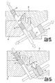
- FIG. 5A shows a first step utilizing an inventive die.
- FIG. 5B shows a subsequent step utilizing the inventive die.
- FIG. 5C shows another subsequent step utilizing the inventive die.
- triangular/trapezoidal shaped passages 122 , 124 , 126 , 128 are desirable.
- the die such as shown in prior art FIGS. 4A-4C cannot manufacture the trapezoidal passages in that it cannot manufacture the spaces for non-parallel ribs.
- the present invention provides a unique die and method that is tailored to produce the ribs such as are illustrated in FIG. 2 .
- a turbine blade formed by this method has an airfoil body 40 having a leading edge 35 and a trailing edge 37 .
- a plurality of cooling channels 130 , 128 , 126 , 124 , and 122 are formed within the body, and separated from adjacent cooling channels by ribs.
- a plurality of the cooling channels communicate with each to form a serpentine flow path for cooling fluid.
- Two pairs of ribs define three intermediate cooling chambers 128 , 126 , and 124 .
- Each rib in each pair extends parallel to the other rib in the pair (that is pairs 42 and 142 ).
- the ribs in a first pair ( 42 ) are non-parallel to the ribs in a second pair ( 142 ).
- a first rib 42 from the first pair is positioned spaced toward the leading edge 35 .
- a first rib 142 of the second pair is then serially positioned spaced toward the trailing edge 37 .
- a second rib 42 of the first pair is then positioned toward the trailing edge relative to the first rib in the second pair.
- a second rib 142 in the second pair is then positioned toward the trailing edge relative to the second rib 42 in the first pair.
- the two pair of ribs define three intermediate cooling channels having a generally triangular or trapezoidal shape.
- the die shown in FIGS. 5A-5C is modified to manufacture the ribs 142 to be parallel to the trailing edge ribs 44 .
- the die halves 80 and 81 have rib extensions 82 and 83 that are not unlike the rib extensions in the prior art.
- the inserts 58 and 59 may operate identically to form the ribs at the leading edge, and even the insert 61 may be similar.
- the insert 84 which forms the trailing edge ribs through rib extensions 87 with the insert 61 , also has rib extensions 86 . Rib extensions 86 form ribs such as the ribs 142 (see FIG. 2 ).
- the die halves 80 and 81 are brought together.
- the inserts 58 and 59 and 60 and 84 are then brought together.
- the rib extensions 86 on the insert 84 will now be in position to form a space for the ribs 142 and 44 .
- the extensions 82 and 83 can form a space for the ribs 42 , either by meeting an abutment (the two leftmost ribs), or by being formed entirely with one rib extension (see rib extension 182 on moving die half 80 ).
- the present invention thus provides a simple method for forming a very complex internal flow passage.
Landscapes
- Engineering & Computer Science (AREA)
- Mechanical Engineering (AREA)
- General Engineering & Computer Science (AREA)
- Turbine Rotor Nozzle Sealing (AREA)
- Molds, Cores, And Manufacturing Methods Thereof (AREA)
Abstract
Description
Claims (2)
Priority Applications (1)
| Application Number | Priority Date | Filing Date | Title |
|---|---|---|---|
| US12/490,705 US7871245B2 (en) | 2005-06-23 | 2009-06-24 | Method for forming turbine blade with angled internal ribs |
Applications Claiming Priority (2)
| Application Number | Priority Date | Filing Date | Title |
|---|---|---|---|
| US11/165,476 US7569172B2 (en) | 2005-06-23 | 2005-06-23 | Method for forming turbine blade with angled internal ribs |
| US12/490,705 US7871245B2 (en) | 2005-06-23 | 2009-06-24 | Method for forming turbine blade with angled internal ribs |
Related Parent Applications (1)
| Application Number | Title | Priority Date | Filing Date |
|---|---|---|---|
| US11/165,476 Division US7569172B2 (en) | 2005-06-23 | 2005-06-23 | Method for forming turbine blade with angled internal ribs |
Publications (2)
| Publication Number | Publication Date |
|---|---|
| US20090269210A1 US20090269210A1 (en) | 2009-10-29 |
| US7871245B2 true US7871245B2 (en) | 2011-01-18 |
Family
ID=37567597
Family Applications (3)
| Application Number | Title | Priority Date | Filing Date |
|---|---|---|---|
| US11/165,476 Active 2027-10-07 US7569172B2 (en) | 2005-06-23 | 2005-06-23 | Method for forming turbine blade with angled internal ribs |
| US12/490,705 Active US7871245B2 (en) | 2005-06-23 | 2009-06-24 | Method for forming turbine blade with angled internal ribs |
| US12/490,721 Active US7862325B2 (en) | 2005-06-23 | 2009-06-24 | Apparatus for forming turbine blade with angled internal ribs |
Family Applications Before (1)
| Application Number | Title | Priority Date | Filing Date |
|---|---|---|---|
| US11/165,476 Active 2027-10-07 US7569172B2 (en) | 2005-06-23 | 2005-06-23 | Method for forming turbine blade with angled internal ribs |
Family Applications After (1)
| Application Number | Title | Priority Date | Filing Date |
|---|---|---|---|
| US12/490,721 Active US7862325B2 (en) | 2005-06-23 | 2009-06-24 | Apparatus for forming turbine blade with angled internal ribs |
Country Status (1)
| Country | Link |
|---|---|
| US (3) | US7569172B2 (en) |
Cited By (10)
| Publication number | Priority date | Publication date | Assignee | Title |
|---|---|---|---|---|
| US20130174997A1 (en) * | 2010-10-06 | 2013-07-11 | Snecma | Mould for producing parts by wax injection |
| US10378364B2 (en) | 2017-11-07 | 2019-08-13 | United Technologies Corporation | Modified structural truss for airfoils |
| US10641100B2 (en) | 2014-04-23 | 2020-05-05 | United Technologies Corporation | Gas turbine engine airfoil cooling passage configuration |
| US10871074B2 (en) | 2019-02-28 | 2020-12-22 | Raytheon Technologies Corporation | Blade/vane cooling passages |
| US11149550B2 (en) | 2019-02-07 | 2021-10-19 | Raytheon Technologies Corporation | Blade neck transition |
| US11220912B2 (en) | 2020-04-16 | 2022-01-11 | Raytheon Technologies Corporation | Airfoil with y-shaped rib |
| US11459897B2 (en) | 2019-05-03 | 2022-10-04 | Raytheon Technologies Corporation | Cooling schemes for airfoils for gas turbine engines |
| US11629602B2 (en) | 2021-06-17 | 2023-04-18 | Raytheon Technologies Corporation | Cooling schemes for airfoils for gas turbine engines |
| US11905849B2 (en) | 2021-10-21 | 2024-02-20 | Rtx Corporation | Cooling schemes for airfoils for gas turbine engines |
| US12065944B1 (en) | 2023-03-07 | 2024-08-20 | Rtx Corporation | Airfoils with mixed skin passageway cooling |
Families Citing this family (24)
| Publication number | Priority date | Publication date | Assignee | Title |
|---|---|---|---|---|
| US7569172B2 (en) * | 2005-06-23 | 2009-08-04 | United Technologies Corporation | Method for forming turbine blade with angled internal ribs |
| FR2914871B1 (en) * | 2007-04-11 | 2009-07-10 | Snecma Sa | TOOLS FOR THE MANUFACTURE OF CERAMIC FOUNDRY CORES FOR TURBOMACHINE BLADES |
| US7866371B2 (en) * | 2007-09-12 | 2011-01-11 | United Technologies Corporation | Lost wax investment casting gating fixtures |
| US8177507B2 (en) | 2008-05-14 | 2012-05-15 | United Technologies Corporation | Triangular serpentine cooling channels |
| JP5717627B2 (en) * | 2008-06-12 | 2015-05-13 | アルストム テクノロジー リミテッドALSTOM Technology Ltd | Blades used in gas turbines and methods for producing such blades by casting technology |
| EP2168698A1 (en) * | 2008-09-26 | 2010-03-31 | Siemens Aktiengesellschaft | Moulded part with separate module for bridges, method for producing a mould, ceramic mould and cast part |
| TW201038388A (en) * | 2009-04-28 | 2010-11-01 | Pegatron Corp | Mold of injection molding |
| EP2450122A1 (en) * | 2010-11-03 | 2012-05-09 | Siemens Aktiengesellschaft | Optimisation of a core forming tool, method for producing a core forming tool and a core forming tool |
| US20130160962A1 (en) * | 2011-12-27 | 2013-06-27 | Bedloe Industries Llc | Main body core set assembly and core box for a coupler body |
| US9404369B2 (en) * | 2012-04-24 | 2016-08-02 | United Technologies Corporation | Airfoil having minimum distance ribs |
| JP5496263B2 (en) * | 2012-06-18 | 2014-05-21 | 三菱重工業株式会社 | Gas turbine blade and gas turbine provided with the same |
| DE102013000320B4 (en) | 2013-01-10 | 2018-10-31 | Audi Ag | Tooling device for the production of a cast component |
| US9835035B2 (en) * | 2013-03-12 | 2017-12-05 | Howmet Corporation | Cast-in cooling features especially for turbine airfoils |
| US20170175532A1 (en) * | 2015-12-21 | 2017-06-22 | United Technologies Corporation | Angled heat transfer pedestal |
| US10315248B2 (en) | 2016-11-17 | 2019-06-11 | General Electric Company | Methods and apparatuses using cast in core reference features |
| GB2571549A (en) * | 2018-03-01 | 2019-09-04 | Rolls Royce Plc | A core for an investment casting process |
| US11104032B2 (en) | 2018-04-19 | 2021-08-31 | General Electric Company | Tooling assembly having cam closing feature |
| US11433627B2 (en) | 2018-09-21 | 2022-09-06 | Kohler Co. | Method of forming fluid channels on a bathtub |
| US10981217B2 (en) | 2018-11-19 | 2021-04-20 | General Electric Company | Leachable casting core and method of manufacture |
| US11021968B2 (en) | 2018-11-19 | 2021-06-01 | General Electric Company | Reduced cross flow linking cavities and method of casting |
| US11111857B2 (en) | 2019-07-18 | 2021-09-07 | Raytheon Technologies Corporation | Hourglass airfoil cooling configuration |
| US11261736B1 (en) * | 2020-09-28 | 2022-03-01 | Raytheon Technologies Corporation | Vane having rib aligned with aerodynamic load vector |
| US11998974B2 (en) | 2022-08-30 | 2024-06-04 | General Electric Company | Casting core for a cast engine component |
| US11866820B1 (en) * | 2022-11-21 | 2024-01-09 | Rtx Corporation | Method of processing a CMC airfoil |
Citations (9)
| Publication number | Priority date | Publication date | Assignee | Title |
|---|---|---|---|---|
| US4283835A (en) | 1980-04-02 | 1981-08-18 | United Technologies Corporation | Cambered core positioning for injection molding |
| US5156526A (en) * | 1990-12-18 | 1992-10-20 | General Electric Company | Rotation enhanced rotor blade cooling using a single row of coolant passageways |
| US5547630A (en) | 1991-10-15 | 1996-08-20 | Callaway Golf Company | Wax pattern molding process |
| US5660524A (en) * | 1992-07-13 | 1997-08-26 | General Electric Company | Airfoil blade having a serpentine cooling circuit and impingement cooling |
| US6530416B1 (en) | 1998-05-14 | 2003-03-11 | Siemens Aktiengesellschaft | Method and device for producing a metallic hollow body |
| US20030133795A1 (en) * | 2002-01-11 | 2003-07-17 | Manning Robert Francis | Crossover cooled airfoil trailing edge |
| US20060051208A1 (en) * | 2004-09-09 | 2006-03-09 | Ching-Pang Lee | Offset coriolis turbulator blade |
| US20060056968A1 (en) * | 2004-09-15 | 2006-03-16 | General Electric Company | Apparatus and methods for cooling turbine bucket platforms |
| US7131818B2 (en) * | 2004-11-02 | 2006-11-07 | United Technologies Corporation | Airfoil with three-pass serpentine cooling channel and microcircuit |
Family Cites Families (34)
| Publication number | Priority date | Publication date | Assignee | Title |
|---|---|---|---|---|
| US2994921A (en) * | 1961-08-08 | Molding device | ||
| US2361348A (en) * | 1939-10-12 | 1944-10-24 | Spalding A G & Bros Inc | Process and apparatus for making balls |
| US3049759A (en) * | 1959-02-18 | 1962-08-21 | Eberhardt Joseph | Injecting moulding apparatus |
| US3074112A (en) * | 1959-04-15 | 1963-01-22 | Joseph A Bobrow | Apparatus for molding an embedment within a plastic mass |
| US3165796A (en) * | 1962-02-07 | 1965-01-19 | Nat Lead Co | Large angular core locking mechanism for die casting |
| US3433292A (en) * | 1966-05-25 | 1969-03-18 | Gen Motors Corp | Locking mechanism for diecasting |
| FR1497569A (en) * | 1966-08-22 | 1967-10-13 | Centre Nat Rech Scient | Very high pressure generating devices |
| US3746493A (en) * | 1968-09-05 | 1973-07-17 | Nibco | Apparatus for molding elbows and the like |
| US3596318A (en) * | 1969-01-07 | 1971-08-03 | Usm Corp | Mold assembly for molding of foamed plastic articles |
| FR2061839A5 (en) * | 1969-05-29 | 1971-06-25 | Crouzet & Cie | |
| US3849053A (en) * | 1971-02-10 | 1974-11-19 | Sterigard Corp | Mold for fabricating the housing of a dispensing valve for pressurized dispensers |
| US3816047A (en) * | 1972-07-18 | 1974-06-11 | Mold & Tool Co Inc E W | Interlock actuating means for mold assembly |
| US3930780A (en) * | 1973-07-20 | 1976-01-06 | Beatrice Foods Co. | Injection molding apparatus for partitioned containers |
| US3969055A (en) * | 1973-12-17 | 1976-07-13 | Globe-Union Inc. | Injection mold control system |
| US3930777A (en) * | 1974-12-11 | 1976-01-06 | Ramsey William C | Plastic u-shaped return conduit and apparatus and method for molding the same |
| US4206799A (en) * | 1978-12-11 | 1980-06-10 | Mcdonald John W | Oblique core locking mechanism for die casting machines |
| US4481161A (en) * | 1983-01-17 | 1984-11-06 | E-W Mold & Tool Company, Inc. | Pressure stabilized injection mold |
| US4676731A (en) * | 1986-01-29 | 1987-06-30 | E-W Mold & Tool Co., Inc. | Injection mold with side and end core locks for forming a partitioned container |
| US4732558A (en) * | 1986-01-29 | 1988-03-22 | E-W Mold & Tool Co., Inc. | Injection mold with end core locks and extended side core locks for forming a partitioned container |
| JPH0783780B2 (en) * | 1989-02-28 | 1995-09-13 | ダイワゴルフ株式会社 | Molds for golf clubs and golf club heads |
| US5167898A (en) * | 1992-03-05 | 1992-12-01 | Triangle Tool Corporation | Injection mold assembly and method for manufacturing a plastic tub with holes |
| US5536161A (en) * | 1993-11-05 | 1996-07-16 | North America Packaging Corporation | Double lock pail mold |
| DE4421566C1 (en) * | 1994-06-20 | 1995-08-24 | Teves Gmbh Alfred | Plastic piston mfr. |
| JP3102748B2 (en) * | 1994-10-19 | 2000-10-23 | 和光化成工業株式会社 | Synthetic resin register for adjusting wind direction and device for molding the same |
| US5865241A (en) * | 1997-04-09 | 1999-02-02 | Exco Technologies Limited | Die casting machine with precisely positionable obliquely moving die core pieces |
| JP4191336B2 (en) * | 1999-09-13 | 2008-12-03 | ブイアイブイエンジニアリング株式会社 | Manufacturing method of gear case |
| US7153125B2 (en) * | 2000-01-19 | 2006-12-26 | Rain Bird Corporation | Molded plastic elbow |
| US6505678B2 (en) * | 2001-04-17 | 2003-01-14 | Howmet Research Corporation | Ceramic core with locators and method |
| AU2003290727A1 (en) * | 2002-11-12 | 2004-06-03 | Entegris, Inc. | Process and apparatus for molding polymer fittings |
| US7001561B2 (en) * | 2002-11-21 | 2006-02-21 | Automotive Products (Usa), Inc. | Right angle tube connector |
| US7216689B2 (en) * | 2004-06-14 | 2007-05-15 | United Technologies Corporation | Investment casting |
| US7172012B1 (en) * | 2004-07-14 | 2007-02-06 | United Technologies Corporation | Investment casting |
| US7569172B2 (en) * | 2005-06-23 | 2009-08-04 | United Technologies Corporation | Method for forming turbine blade with angled internal ribs |
| US7381051B2 (en) * | 2006-01-24 | 2008-06-03 | Cheng Uei Precision Industry Co., Ltd. | Core-pulling mechanism and injection mold with the same |
-
2005
- 2005-06-23 US US11/165,476 patent/US7569172B2/en active Active
-
2009
- 2009-06-24 US US12/490,705 patent/US7871245B2/en active Active
- 2009-06-24 US US12/490,721 patent/US7862325B2/en active Active
Patent Citations (9)
| Publication number | Priority date | Publication date | Assignee | Title |
|---|---|---|---|---|
| US4283835A (en) | 1980-04-02 | 1981-08-18 | United Technologies Corporation | Cambered core positioning for injection molding |
| US5156526A (en) * | 1990-12-18 | 1992-10-20 | General Electric Company | Rotation enhanced rotor blade cooling using a single row of coolant passageways |
| US5547630A (en) | 1991-10-15 | 1996-08-20 | Callaway Golf Company | Wax pattern molding process |
| US5660524A (en) * | 1992-07-13 | 1997-08-26 | General Electric Company | Airfoil blade having a serpentine cooling circuit and impingement cooling |
| US6530416B1 (en) | 1998-05-14 | 2003-03-11 | Siemens Aktiengesellschaft | Method and device for producing a metallic hollow body |
| US20030133795A1 (en) * | 2002-01-11 | 2003-07-17 | Manning Robert Francis | Crossover cooled airfoil trailing edge |
| US20060051208A1 (en) * | 2004-09-09 | 2006-03-09 | Ching-Pang Lee | Offset coriolis turbulator blade |
| US20060056968A1 (en) * | 2004-09-15 | 2006-03-16 | General Electric Company | Apparatus and methods for cooling turbine bucket platforms |
| US7131818B2 (en) * | 2004-11-02 | 2006-11-07 | United Technologies Corporation | Airfoil with three-pass serpentine cooling channel and microcircuit |
Cited By (11)
| Publication number | Priority date | Publication date | Assignee | Title |
|---|---|---|---|---|
| US20130174997A1 (en) * | 2010-10-06 | 2013-07-11 | Snecma | Mould for producing parts by wax injection |
| US8763678B2 (en) * | 2010-10-06 | 2014-07-01 | Snecma | Mold for producing parts by wax injection |
| US10641100B2 (en) | 2014-04-23 | 2020-05-05 | United Technologies Corporation | Gas turbine engine airfoil cooling passage configuration |
| US10378364B2 (en) | 2017-11-07 | 2019-08-13 | United Technologies Corporation | Modified structural truss for airfoils |
| US11149550B2 (en) | 2019-02-07 | 2021-10-19 | Raytheon Technologies Corporation | Blade neck transition |
| US10871074B2 (en) | 2019-02-28 | 2020-12-22 | Raytheon Technologies Corporation | Blade/vane cooling passages |
| US11459897B2 (en) | 2019-05-03 | 2022-10-04 | Raytheon Technologies Corporation | Cooling schemes for airfoils for gas turbine engines |
| US11220912B2 (en) | 2020-04-16 | 2022-01-11 | Raytheon Technologies Corporation | Airfoil with y-shaped rib |
| US11629602B2 (en) | 2021-06-17 | 2023-04-18 | Raytheon Technologies Corporation | Cooling schemes for airfoils for gas turbine engines |
| US11905849B2 (en) | 2021-10-21 | 2024-02-20 | Rtx Corporation | Cooling schemes for airfoils for gas turbine engines |
| US12065944B1 (en) | 2023-03-07 | 2024-08-20 | Rtx Corporation | Airfoils with mixed skin passageway cooling |
Also Published As
| Publication number | Publication date |
|---|---|
| US7569172B2 (en) | 2009-08-04 |
| US20090258102A1 (en) | 2009-10-15 |
| US20090269210A1 (en) | 2009-10-29 |
| US7862325B2 (en) | 2011-01-04 |
| US20060292005A1 (en) | 2006-12-28 |
Similar Documents
| Publication | Publication Date | Title |
|---|---|---|
| US7871245B2 (en) | Method for forming turbine blade with angled internal ribs | |
| US10500633B2 (en) | Gas turbine engine airfoil impingement cooling | |
| RU2261995C2 (en) | Microcontour to provide passing of cooling gas flow through part and method of manufacturing of part with cooling channels | |
| EP1055800B1 (en) | Turbine airfoil with internal cooling | |
| EP2071126B1 (en) | Turbine blades and methods of manufacturing | |
| EP3351728B1 (en) | Rotor blade and rotor blade manufacturing method | |
| JP6348965B2 (en) | Additive manufacturing method for adding structures in cooling holes | |
| US8366383B2 (en) | Air sealing element | |
| EP2159375B1 (en) | A turbine engine airfoil with convective cooling, the corresponding core and the method for manufacturing this airfoil | |
| CN1970998A (en) | Microcircuit cooling for vanes | |
| JP6613803B2 (en) | Blade, gas turbine provided with the blade, and method of manufacturing the blade | |
| US11230929B2 (en) | Turbine component with dust tolerant cooling system | |
| EP2385216B1 (en) | Turbine airfoil with body microcircuits terminating in platform | |
| US20110236222A1 (en) | Blade for a gas turbine and casting technique method for producing same | |
| EP3296037B1 (en) | Method of forming a gas turbine component with cooling aperture having shaped inlet | |
| US20210078070A1 (en) | Methods and apparatuses using cast in core reference features | |
| US11333042B2 (en) | Turbine blade with dust tolerant cooling system | |
| JP6986834B2 (en) | Articles and methods for cooling articles | |
| EP3803057B1 (en) | Airfoil for a turbine engine incorporating pins | |
| JPS6170104A (en) | Gas turbine |
Legal Events
| Date | Code | Title | Description |
|---|---|---|---|
| STCF | Information on status: patent grant |
Free format text: PATENTED CASE |
|
| FPAY | Fee payment |
Year of fee payment: 4 |
|
| MAFP | Maintenance fee payment |
Free format text: PAYMENT OF MAINTENANCE FEE, 8TH YEAR, LARGE ENTITY (ORIGINAL EVENT CODE: M1552) Year of fee payment: 8 |
|
| AS | Assignment |
Owner name: RAYTHEON TECHNOLOGIES CORPORATION, MASSACHUSETTS Free format text: CHANGE OF NAME;ASSIGNOR:UNITED TECHNOLOGIES CORPORATION;REEL/FRAME:054062/0001 Effective date: 20200403 |
|
| AS | Assignment |
Owner name: RAYTHEON TECHNOLOGIES CORPORATION, CONNECTICUT Free format text: CORRECTIVE ASSIGNMENT TO CORRECT THE AND REMOVE PATENT APPLICATION NUMBER 11886281 AND ADD PATENT APPLICATION NUMBER 14846874. TO CORRECT THE RECEIVING PARTY ADDRESS PREVIOUSLY RECORDED AT REEL: 054062 FRAME: 0001. ASSIGNOR(S) HEREBY CONFIRMS THE CHANGE OF ADDRESS;ASSIGNOR:UNITED TECHNOLOGIES CORPORATION;REEL/FRAME:055659/0001 Effective date: 20200403 |
|
| MAFP | Maintenance fee payment |
Free format text: PAYMENT OF MAINTENANCE FEE, 12TH YEAR, LARGE ENTITY (ORIGINAL EVENT CODE: M1553); ENTITY STATUS OF PATENT OWNER: LARGE ENTITY Year of fee payment: 12 |
|
| AS | Assignment |
Owner name: RTX CORPORATION, CONNECTICUT Free format text: CHANGE OF NAME;ASSIGNOR:RAYTHEON TECHNOLOGIES CORPORATION;REEL/FRAME:064714/0001 Effective date: 20230714 |