US7867121B2 - Metal V-belt - Google Patents
Metal V-belt Download PDFInfo
- Publication number
- US7867121B2 US7867121B2 US12/252,977 US25297708A US7867121B2 US 7867121 B2 US7867121 B2 US 7867121B2 US 25297708 A US25297708 A US 25297708A US 7867121 B2 US7867121 B2 US 7867121B2
- Authority
- US
- United States
- Prior art keywords
- metal
- metal ring
- metal element
- ear
- protrusion
- Prior art date
- Legal status (The legal status is an assumption and is not a legal conclusion. Google has not performed a legal analysis and makes no representation as to the accuracy of the status listed.)
- Active
Links
Images


Classifications
-
- F—MECHANICAL ENGINEERING; LIGHTING; HEATING; WEAPONS; BLASTING
- F16—ENGINEERING ELEMENTS AND UNITS; GENERAL MEASURES FOR PRODUCING AND MAINTAINING EFFECTIVE FUNCTIONING OF MACHINES OR INSTALLATIONS; THERMAL INSULATION IN GENERAL
- F16G—BELTS, CABLES, OR ROPES, PREDOMINANTLY USED FOR DRIVING PURPOSES; CHAINS; FITTINGS PREDOMINANTLY USED THEREFOR
- F16G5/00—V-belts, i.e. belts of tapered cross-section
- F16G5/16—V-belts, i.e. belts of tapered cross-section consisting of several parts
Definitions
- the present invention relates to a metal V-belt including a metal ring having an endless belt shape and a plurality of metal elements supported by the metal ring in the longitudinal direction of the metal ring. More particularly, the present invention relates to a metal V-belt wherein contact of an innermost periphery of the metal ring with a saddle surface of a metal element, and contact of a protrusion and corresponding concavity of neighboring metal rings is avoided when exiting a driven pulley.
- Japanese Patent No. 3755833 discloses a driving belt wherein a concavity for receiving a carrier (a metal belt) is provided in a transverse-direction member (a metal element) having a supporting surface and a top portion surface.
- a point at which the transverse-direction member, while in an inclined state, contacts a supporting surface is called a first contact point and a point at which the transverse-direction member, again while in an inclined state, contacts the top portion surface is called a second contact point, by specifying 0.2 ⁇ tan ⁇ (B/A) ⁇ 0.8, where A is the distance between the first and second contact points along the axial direction of a driving belt (a metal V-belt) in a position where the transverse-direction member is straight, and B is the distance between the carrier and the second contact point along the radial direction of the driving belt in a position where the transverse-direction member is straight.
- the disclosed driving belt improves engagement into a drive pulley and a driven pulley by preventing the
- the transverse-direction member has sufficient play for positioning itself with respect to the carrier and the pulleys, and the inclination of the transverse-direction member is prevented in order to ensure a good wedge action in the pulleys.
- a play is necessary for inclination between a protrusion and a concavity that engage each other and the play moves the transverse-direction member laterally, with the result that the transverse-direction member and pulleys are apt to come into contact with each other during entry into the pulleys, making it necessary to increase the strength of the transverse-direction member.
- Japanese Patent No. 3605570 discloses a metal V-belt in which a maximum rolling angle of one metal element relative to upstream-side metal elements is controlled by the engagement between a protrusion and a concavity, wherein the rolling of metal elements is controlled without the metal ring abutting against the metal elements.
- the metal V-belt disclosed by JP '570 is intended to solve the problem in the technique disclosed in JP '833.
- a maximum rolling angle of one metal element relative to upstream-side metal elements is controlled by the engagement between a protrusion and a concavity, which requires increasing the strength of the engaging portion.
- Japanese Patent Application Laid-open No. 2000-193041 discloses known a metal V-belt having an improved or increased durability that is achieved by setting a clearance between a side surface of a slot of a metal element and a metal ring at a value larger than a clearance in the belt thickness direction between a protrusion and a concavity of the metal element, which prevents the generation of a compressive stress that pinches and bends the metal ring.
- the present invention has been made in view of such circumstances and has as an aspect a metal V-belt in which the durability of the entire metal V-belt is improved without having to increase the strength of the protrusion and concavity of the metal element.
- a metal V-belt including a metal ring having an endless belt shape; and a plurality of metal elements supported by the metal ring in the longitudinal direction of the metal ring.
- the metal V-belt is wound on a drive pulley and a driven pulley and transmits power between the drive pulley and the driven pulley.
- the metal element includes front and rear main surfaces; a pair of right and left slots that receive the metal ring between a saddle surface and an ear-part bottom surface connecting the front and rear main surfaces; a protrusion provided in a protruding manner on one of the front and rear main surfaces; and a concavity provided in a depressed manner in the other of the front and rear main surfaces so as to engage the protrusion of a neighboring metal element.
- a clearance is defined between an outermost peripheral surface of the metal ring and the ear-part bottom surface of the metal element, wherein at an exit of the driven pulley where top portions of the front and rear main surfaces of the metal elements that are adjacent to each other in the longitudinal direction of the metal ring contact each other, and the outermost peripheral surface of the metal ring contacts the ear-part bottom surface of the metal element, contact between the innermost peripheral surface of the metal ring and the saddle surface of the metal element, and contact between the protrusion and concavity of neighboring metal elements is avoided.
- the clearance between the outermost peripheral surface of the metal ring and the ear-part bottom surface of the metal element is set to have too small of a value, at an exit of a driven pulley where top portions of the front main surface and rear main surface of the metal elements that are adjacent to each other in the longitudinal direction of the metal ring come into contact with each other, and where the outermost peripheral surface of the metal ring comes into contact with the ear-part bottom surface of the metal element, the innermost peripheral surface of the metal ring first contacts the saddle surface of the metal element and prevents the relative slip of the metal ring and the metal element, with the result that the service life of the metal ring and the metal element is shortened.
- the clearance between the outermost peripheral surface of the metal ring and the ear-part bottom surface of the metal element is set to have too large of a value, at an exit of a driven pulley where top portions of the front main surface and rear main surface of the metal elements that are adjacent to each other in the longitudinal direction of the metal ring come into contact with each other, and where the outermost peripheral surface of the metal ring contacts the ear-part bottom surface of the metal element, the protrusion and the concavity contact each other with the result of the contact portion becoming worn.
- FIG. 1 is a schematic diagram of a power transmission system of a vehicle
- FIG. 2 is a partial perspective view of a metal V-belt according to a preferred embodiment of the present invention
- FIG. 3 is a diagram viewed in the direction of arrow 3 in FIG. 2 ;
- FIG. 4 is a sectional view taken along line 4 - 4 in FIG. 3 ;
- FIG. 5 is a side view of a metal V-belt wound on a drive pulley and a driven pulley;
- FIG. 6 is an enlarged view of a portion of the metal ring indicated by the arrow A in FIG. 5 when the clearance between the outermost periphery and the bottom surface of the ear part of the metal ring is small;
- FIG. 7 is an enlarged view of a portion of a metal ring indicated by the arrow A in FIG. 5 when the clearance between the outermost periphery and the bottom surface of the ear part of the metal ring is large;
- FIG. 8 is an enlarged view of a portion indicated the arrow A in FIG. 5 when the clearance between the outermost periphery and the bottom surface of the ear part of the metal ring is an appropriate value;
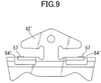
- FIG. 9 is a front view of a test piece for measuring the contact reaction force between the rear end of the saddle surface and the metal ring;
- FIG. 10 is a diagram showing measurement results of the contact reaction force between the rear end of the saddle surface and the metal ring;
- FIG. 11 is a diagram showing changes in the gap between metal elements and the gap between the metal ring and the metal element at the outlet of the driven pulley when the clearance between the outermost periphery and the bottom surface of the ear part of the metal ring is changed;
- FIG. 12 is a diagram that compares durability observed when the clearance between the outermost periphery and the bottom surface of the ear part of the metal ring is changed.
- FIG. 2 An embodiment of the present invention will be described below with reference to FIGS. 1 to 12 .
- the definitions of the forward, backward, rightward, and leftward directions of a metal element used in this embodiment are shown in FIG. 2 .
- an input shaft 13 connected to a crankshaft 11 of an engine E via a damper 12 is connected to a drive shaft 15 of a metal belt type continuously variable transmission T by a starting clutch 14 .
- the drive shaft 15 is provided with a drive pulley 16
- a driven shaft 20 disposed parallel to the drive shaft 15 is provided with a driven pulley 21
- a metal V-belt 25 according to a preferred embodiment of the present invention is wound on the drive pulley 16 and the driven pulley 21 .
- the drive pulley 16 is provided with a fixed-side pulley half body 17 fixed to the drive shaft 15 and a movable-side pulley half body 18 capable of moving toward and away from the fixed-side pulley half body 17 , and the movable-side pulley half body 18 is urged toward the fixed-side pulley half body 17 under hydraulic pressure acting on an oil chamber 19 .
- the driven pulley 21 is provided with a fixed-side pulley half body 22 fixed to the driven shaft 20 and a movable-side pulley half body 23 capable of moving toward and away from the fixed-side pulley half body 22 , and the movable-side pulley half body 23 is urged toward the fixed-side pulley half body 22 under hydraulic pressure acting on an oil chamber 24 .
- a forward-movement drive gear 26 and a reverse-movement drive gear 27 are supported by the driven shaft 20 to be relatively rotatable, and the forward-movement drive gear 26 and the reverse-movement drive gear 27 can be selectively coupled to the driven shaft 20 by a selector 28 .
- a forward-movement driven gear 30 meshing with the forward-movement drive gear 26 and a reverse-movement driven gear 32 meshing with the reverse-movement drive gear 27 are fixed to an output shaft 29 disposed parallel to the driven shaft 20 via a reverse-movement idle gear 31 .
- the rotation of the output shaft 29 is input to a differential gear 35 via a final drive gear 33 and a final driven gear 34 and transmitted from the differential gear 35 to driving wheels W, W via left and right axles 36 , 36 .
- the driving force of the engine E is transmitted to the driven shaft 20 via the crankshaft 11 , the damper 12 , the input shaft 13 , the starting clutch 14 , the drive shaft 15 , the drive pulley 16 , the metal V-belt 25 , and the driven pulley 21 .
- the driving force of the driven shaft 20 is transmitted to the output shaft 29 via the forward-movement drive gear 26 and the forward-movement driven gear 30 , which causes the vehicle to be driven in a forward direction.
- the driving force of the driven shaft 20 is transmitted to the output shaft 29 via the reverse-movement drive gear 27 , the reverse-movement idle gear 31 , and the reverse-movement driven gear 32 , which causes the vehicle to be driven in a backward or reverse direction.
- the transmission gear ratio is adjusted in a stepless manner. That is, if the hydraulic pressure acting on the oil chamber 24 of the driven pulley 21 is increased relative to the hydraulic pressure acting on the oil chamber 19 of the drive pulley 16 , then the groove width of the driven pulley 21 decreases and the effective radius increases, as a result of which, the groove width of the drive pulley 16 increases and the effective radius decreases. Therefore, the transmission gear ratio of the transmission T changes in a stepless manner toward LOW.
- the metal V-belt 25 includes a pair of left and right belt-shape metal rings 41 , 41 , and a plurality of metal elements 42 supported by the metal rings 41 , 41 .
- Each of the metal rings 41 includes a plurality of laminated belt-shaped ring plates 43 .
- the metal element 42 is formed by blanking a metal plate material, and has an element main part 44 with a substantially trapezoidal shape, a neck part 46 located between a pair of right and left slots 45 , 45 that receive the metal rings 41 , 41 therein, and an ear part 47 having a substantially triangular shape, which is connected to an upper part of the element main part 44 via the neck part 46 .
- a pair of pulley abutment surfaces 49 , 49 that abut against V-grooves 48 , 48 of the drive pulley 16 and driven pulley 21 are formed in both end portions of the element main part 44 in the leftward and rightward directions.
- a front main surface 50 f and a rear main surface 50 r are formed on the front and rear sides of the movement direction of the metal element 42 .
- the front main surface 50 f of the succeeding metal element 42 in the movement direction abuts against the preceding rear main surface 50 r of the preceding metal element 42 in the movement direction.
- an inclined surface 52 is formed via a locking edge 51 that extends in the leftward and rightward directions.
- a circular protrusion 53 f is provided in a protruding manner on either a front surface of the ear part 47 (the front main surface 50 f ) or a rear surface thereof (the rear main surface 50 r ).
- the protrusion 53 f is provided on the front surface of the ear part 47 (the front main surface 50 f ).
- a correspondingly shaped or circular concavity 53 r is defined in the other of the front main surface and the rear main surface of the ear part 47 (the rear main surface 50 r ).
- opposite side surfaces of the slot 45 include a saddle surface 54 and an ear-part bottom surface 55 that connect the front main surface 50 f and the rear main surface 50 r .
- the metal rings 41 , 41 are received by the slots 45 , 45 defined between the saddle surfaces 54 , 54 and the ear-part bottom surfaces 55 , 55 .
- Inner peripheral surfaces of the metal rings 41 , 41 abut against the saddle surfaces 54 , 54
- outer peripheral surfaces of the metal rings 41 , 41 abut against the ear-part bottom surfaces 55 , 55 .
- the ear-part bottom surface 55 is formed to be inclined such that the ear-part bottom surface 55 is spaced farther from the saddle surface 54 than the ear-part bottom surface 55 is spaced from the neck part 46 .
- the saddle surface 54 is formed to be slightly arched and bulged toward the ear-part bottom surface 55 side.
- the metal V-belt 25 wound on the drive pulley 16 and the driven pulley 21 is such that according to the rotation of the drive pulley 16 indicated by the arrows, in a chord part moving from the drive pulley 16 toward the driven pulley 21 , i.e., a tension-side chord part that performs the transmission of the driving force, adjacent metal elements 42 abut against each other and cause a pressing force to act on each other.
- the metal elements 42 that have performed power transmission from the drive pulley 16 to the driven pulley 21 in a dense condition without a gap therebetween move out, at the exit of the driven pulley 21 , to the loose-side chord part while keeping the posture within the driven pulley 21 , and in the loose-side chord part, gaps are generated between the metal elements 42 .
- the metal ring 41 is in a linearly tensed condition due to the tension between the driven pulley 21 and the drive pulley 16 . From results of a numerical analysis, as shown in FIGS.
- the contact reaction force between the rear ends of the saddle surfaces 54 in the metal element 42 and the metal ring 41 was measured by using a test piece 42 ′, as shown in FIG. 9 .
- the test piece 42 ′ has a shape wherein a partial surface of the rear ends of the saddle surfaces 54 in the metal element 42 are left as sensing parts 57 and the remaining surface of the saddle surface 54 is ground to a depth at which the remaining surface ceases to come into contact with the metal ring 41 .
- part of the portion corresponding to the element main part 44 is worked as a sensing lever 54 ′ and a sensor is attached to the sensing levers 54 ′.
- the output from the sensing parts 57 is weak when the test piece 42 ′ is sandwiched between preceding and succeeding metal elements 42 in a vertical posture with respect to the metal ring 41 , whereas strong signals are output from the sensing parts 57 when the test piece 42 ′ has assumed a forward inclined posture.
- a signal of strong waveform is output when the test piece 42 ′ makes a shift from the part wound on the driven pulley 21 to the loose-side chord part, that is, at the exit of the driven pulley 21 .
- the metal element 42 moves out from the driven pulley 21 in a forward inclined posture, as shown in FIGS. 6 to 8 , at the exit of the driven pulley 21 , the top portions of the front main surface 50 f and rear main surface 50 r of adjacent metal elements 42 , 42 in the longitudinal direction of the metal ring 41 contact each other at a contact point P 1 and the outermost periphery of the metal ring 41 comes into contact with the ear-part bottom surface 55 at a contact point P 2 .
- the innermost periphery of the metal ring 41 first contacts the saddle surfaces 54 of the metal element 42 at the contact point P 3 . Thereafter, the top portions of the front main surface 50 f and rear main surface 50 r of the metal elements 42 , 42 that are adjacent to each other in the longitudinal direction of the metal ring 41 contact each other at the contact point P 1 , and at the same time, the outermost peripheral surface of the metal ring 41 contacts the ear-part bottom surface 55 at the contact point P 2 .
- the protrusion 53 f of a succeeding metal element 42 first contacts the concavity 53 r of a preceding metal element 42 at a contact point P 4 , thereafter, the top portions of the front main surface 50 f and rear main surface 50 r of the metal elements 42 , 42 that are adjacent to each other in the longitudinal direction of the metal ring 41 contact each other at the contact point P 1 , and at the same time, the outermost peripheral surface of the metal ring 41 contacts the ear-part bottom surface 55 at the contact point P 2 .
- top portions of the front main surface 50 f and rear main surface 50 r of the metal elements 42 , 42 that are adjacent to each other come into contact with each other at the contact point P 1 and, at the same time, the outermost periphery of the metal ring 41 comes into contact with the ear-part bottom surface 55 at the contact point P 2 .
- the clearance d that occurs when the gap between the saddle surfaces 54 of the metal element 42 and the innermost periphery of the metal ring 41 is “0,” that is, when the innermost peripheral surface of the metal ring 41 first comes into contact with the saddle surface 54 , and is denoted by dmin
- the clearance d that occurs when the gap between the protrusion 53 f and the concavity 53 r is “0,” that is, when the protrusion 53 f and the concavity 53 r first come into contact, and is denoted by dmax
- the clearance d is set to satisfy the relationship where dmin ⁇ d ⁇ dmax holds.
- the top portions of the front main surface 50 f and rear main surface 50 r of the metal elements 42 , 42 that are adjacent to each other in the longitudinal direction of the metal ring 41 come into contact with each other at the contact point P 1 , and the outermost peripheral surface of the metal ring 41 comes into contact with the ear-part bottom surface 55 at the contact point P 2 , only whereby it is possible to ensure a gap between the saddle surfaces 54 of the metal element 42 and the innermost peripheral surface of the metal ring 41 , and it is possible to ensure a gap between the protrusion 53 f and the concavity 53 r of the metal elements 42 , 42 .
- the clearance d between the outermost peripheral surface of the metal ring 41 and the ear-part bottom surfaces 55 is set at a value that avoids, at the exit of the driven pulley 21 , the innermost peripheral surface of the metal ring 41 from contacting the saddle surfaces 54 , and avoids mutual contact between the protrusion 53 f and the concavity 53 r of neighboring metal elements 42 , 42 .
- the protrusion 53 f of a succeeding metal element 42 engages the concavity 53 r of a preceding metal element 42 that has entered the drive pulley 16 first, and the succeeding metal element 42 smoothly enters the drive pulley 16 while avoiding contact with the drive pulley 16 .
- the durability of the metal V-belt 25 is compared for cases where the clearance d is increased and decreased. As shown in FIG. 12 , compared to the durability that is observed when the clearance d is set at a value not more than the clearance dmin occurring when the gap between the saddle surfaces 54 of the metal element 42 and the innermost peripheral surface of the metal ring 41 is “0” at the exit of the driven pulley 21 , that is, the innermost peripheral surface of the metal ring 41 first comes into contact with the saddle surfaces 54 , and compared to the durability that is observed when the clearance d is set at a value not less than the clearance dmax occurring when the gap between the protrusion 53 f and the concavity 53 r is “0” at the exit of the driven pulley 21 , that is, when the protrusion 53 f first comes into contact with the concavity 53 r , it is possible to increase the durability that is observed when the clearance d is set at a value that avoids, at the exit of the driven pulley 21
- the mark ⁇ indicates a condition in which breakage occurred
- the mark ⁇ which is obtained when the clearance d , is set at a value larger than dmin and smaller than dmax, indicates a condition in which breakage has not occurred and additional service life results.
- dmin is defined as ⁇ (minimum distance between saddle surface 54 and ear-part bottom surface 55 ) ⁇ 3 ⁇ (layer thickness of metal ring 41 ) ⁇
- dmax is defined as ⁇ (minimum distance between saddle surface 54 and ear-part bottom surface 55 )+3 ⁇ (layer thickness of metal ring 41 ) ⁇ .
- the protrusion 53 f is provided in a protruding manner on the front main surface 50 f and the concavity 53 r is provided in a depressed manner in the rear main surface 50 r , the locations of the protrusion 53 f and concavity 53 r can be reversed.
Landscapes
- Engineering & Computer Science (AREA)
- General Engineering & Computer Science (AREA)
- Mechanical Engineering (AREA)
- Transmissions By Endless Flexible Members (AREA)
Abstract
Description
Claims (2)
dmin={(a minimum distance between the saddle surface and the ear-part bottom surface)−3σ−(a layer thickness of the metal ring)}, and
dmax ={(the minimum distance between the saddle surface and the ear-part bottom surface)+3σ−(the layer thickness of metal ring)}.
Applications Claiming Priority (2)
| Application Number | Priority Date | Filing Date | Title |
|---|---|---|---|
| JP2007-278179 | 2007-10-25 | ||
| JP2007278179A JP4447031B2 (en) | 2007-10-25 | 2007-10-25 | Metal V belt |
Publications (2)
| Publication Number | Publication Date |
|---|---|
| US20090111633A1 US20090111633A1 (en) | 2009-04-30 |
| US7867121B2 true US7867121B2 (en) | 2011-01-11 |
Family
ID=40070949
Family Applications (1)
| Application Number | Title | Priority Date | Filing Date |
|---|---|---|---|
| US12/252,977 Active US7867121B2 (en) | 2007-10-25 | 2008-10-16 | Metal V-belt |
Country Status (3)
| Country | Link |
|---|---|
| US (1) | US7867121B2 (en) |
| EP (1) | EP2053269B1 (en) |
| JP (1) | JP4447031B2 (en) |
Cited By (2)
| Publication number | Priority date | Publication date | Assignee | Title |
|---|---|---|---|---|
| US10094446B2 (en) * | 2013-06-04 | 2018-10-09 | Honda Motor Co., Ltd. | Metal belt for continuously variable transmission |
| US10612653B2 (en) * | 2016-11-04 | 2020-04-07 | Honda Motor Co., Ltd. | Metal element for continuously variable transmission and method of manufacturing metal element for continuously variable transmission |
Families Citing this family (6)
| Publication number | Priority date | Publication date | Assignee | Title |
|---|---|---|---|---|
| WO2014156432A1 (en) * | 2013-03-28 | 2014-10-02 | 本田技研工業株式会社 | Metal belt for continuously variable transmission |
| JP2015194226A (en) * | 2014-03-31 | 2015-11-05 | 本田技研工業株式会社 | Continuously variable transmission metal belt |
| JP6506062B2 (en) * | 2015-03-24 | 2019-04-24 | 本田技研工業株式会社 | Method of manufacturing metal element for continuously variable transmission |
| WO2017138528A1 (en) * | 2016-02-12 | 2017-08-17 | アイシン・エィ・ダブリュ株式会社 | Transmission belt |
| EP3431810A4 (en) * | 2016-05-18 | 2019-05-01 | Aisin Aw Co., Ltd. | Transmission belt |
| NL1043501B1 (en) * | 2019-12-10 | 2021-08-31 | Bosch Gmbh Robert | A transverse segment for a drive belt and a drive belt for a continuously variable transmission including the transverse segment and a ring stack |
Citations (6)
| Publication number | Priority date | Publication date | Assignee | Title |
|---|---|---|---|---|
| EP0626526A1 (en) | 1993-05-24 | 1994-11-30 | Van Doorne's Transmissie B.V. | Drive belt |
| EP1013964A2 (en) | 1998-12-24 | 2000-06-28 | Honda Giken Kogyo Kabushiki Kaisha | Metal V-belt |
| EP1018608A1 (en) | 1999-01-08 | 2000-07-12 | Honda Giken Kogyo Kabushiki Kaisha | Metal belt |
| JP2001200894A (en) | 2000-01-19 | 2001-07-27 | Honda Motor Co Ltd | Continuously variable transmission belt |
| EP1231407A1 (en) | 2001-02-13 | 2002-08-14 | Honda Giken Kogyo Kabushiki Kaisha | Belt for continuously variable transmission |
| US6440023B2 (en) * | 1998-08-31 | 2002-08-27 | Honda Giken Kogyo Kabushiki Kaisha | Metal V-belt |
-
2007
- 2007-10-25 JP JP2007278179A patent/JP4447031B2/en active Active
-
2008
- 2008-10-09 EP EP08166217A patent/EP2053269B1/en not_active Expired - Fee Related
- 2008-10-16 US US12/252,977 patent/US7867121B2/en active Active
Patent Citations (12)
| Publication number | Priority date | Publication date | Assignee | Title |
|---|---|---|---|---|
| EP0626526A1 (en) | 1993-05-24 | 1994-11-30 | Van Doorne's Transmissie B.V. | Drive belt |
| JP3755833B2 (en) | 1993-05-24 | 2006-03-15 | バン・ドールネズ・トランスミツシー・ベー・ブイ | Driving belt |
| US6440023B2 (en) * | 1998-08-31 | 2002-08-27 | Honda Giken Kogyo Kabushiki Kaisha | Metal V-belt |
| EP1013964A2 (en) | 1998-12-24 | 2000-06-28 | Honda Giken Kogyo Kabushiki Kaisha | Metal V-belt |
| JP2000193041A (en) | 1998-12-24 | 2000-07-14 | Honda Motor Co Ltd | Metallic v-belt |
| EP1018608A1 (en) | 1999-01-08 | 2000-07-12 | Honda Giken Kogyo Kabushiki Kaisha | Metal belt |
| US6342020B1 (en) * | 1999-01-08 | 2002-01-29 | Honda Giken Kogyo Kabushiki Kaisha | Metal belt |
| JP2001200894A (en) | 2000-01-19 | 2001-07-27 | Honda Motor Co Ltd | Continuously variable transmission belt |
| EP1172582A1 (en) | 2000-01-19 | 2002-01-16 | Honda Giken Kogyo Kabushiki Kaisha | Belt for non-stage transmissions |
| US6755760B2 (en) * | 2000-01-19 | 2004-06-29 | Honda Giken Kogyo Kabushiki Kaisha | Belt for non-stage transmissions |
| EP1231407A1 (en) | 2001-02-13 | 2002-08-14 | Honda Giken Kogyo Kabushiki Kaisha | Belt for continuously variable transmission |
| JP3605570B2 (en) | 2001-02-13 | 2004-12-22 | 本田技研工業株式会社 | Belt for continuously variable transmission |
Cited By (2)
| Publication number | Priority date | Publication date | Assignee | Title |
|---|---|---|---|---|
| US10094446B2 (en) * | 2013-06-04 | 2018-10-09 | Honda Motor Co., Ltd. | Metal belt for continuously variable transmission |
| US10612653B2 (en) * | 2016-11-04 | 2020-04-07 | Honda Motor Co., Ltd. | Metal element for continuously variable transmission and method of manufacturing metal element for continuously variable transmission |
Also Published As
| Publication number | Publication date |
|---|---|
| EP2053269A1 (en) | 2009-04-29 |
| US20090111633A1 (en) | 2009-04-30 |
| JP4447031B2 (en) | 2010-04-07 |
| JP2009103293A (en) | 2009-05-14 |
| EP2053269B1 (en) | 2012-08-01 |
Similar Documents
| Publication | Publication Date | Title |
|---|---|---|
| US7867121B2 (en) | Metal V-belt | |
| EP1067311B1 (en) | Belt for continuously variable transmission | |
| EP1754912B1 (en) | Power transmission chain and power transmission device | |
| EP1162387B1 (en) | Belt for non-stage transmissions | |
| US6755760B2 (en) | Belt for non-stage transmissions | |
| US6612954B2 (en) | Belt for continuously variable transmission | |
| US8617017B2 (en) | Power transmission chain | |
| EP0964184B1 (en) | Metal V-belt | |
| US6599212B2 (en) | Belt for continuously variable transmission | |
| EP1840408B1 (en) | Power transmission chain, and power transmission system having the same | |
| JP4505316B2 (en) | Belt for continuously variable transmission | |
| US6336884B1 (en) | Belt for continuously variable transmission | |
| US20030084583A1 (en) | Method for measuring free-state diameter of metal ring | |
| JP2006226405A (en) | Power transmission chain and power transmission device equipped with the same | |
| JP4803340B2 (en) | Endless belt for transmission and belt-type continuously variable transmission using the same | |
| EP1130283B1 (en) | Thin metal ring for metal belt type nonstep variable-speed transmission | |
| JP4737511B2 (en) | Power transmission chain and power transmission device including the same | |
| JP2007010050A (en) | Power transmission chain and power transmission device equipped therewith | |
| JP2009228748A (en) | Power transmission chain, power transmission device having the same and method of manufacturing power transmission chain | |
| JP2006145010A (en) | Power transmission chain and power transmission device having the same | |
| JP2007263178A (en) | Power transmitting chain and power transmission having the same |
Legal Events
| Date | Code | Title | Description |
|---|---|---|---|
| AS | Assignment |
Owner name: HONDA MOTOR CO., LTD., JAPAN Free format text: ASSIGNMENT OF ASSIGNORS INTEREST;ASSIGNORS:YAGASAKI, TORU;AOYAMA, HIDEAKI;REEL/FRAME:021964/0480 Effective date: 20081119 |
|
| FEPP | Fee payment procedure |
Free format text: PAYOR NUMBER ASSIGNED (ORIGINAL EVENT CODE: ASPN); ENTITY STATUS OF PATENT OWNER: LARGE ENTITY |
|
| STCF | Information on status: patent grant |
Free format text: PATENTED CASE |
|
| FPAY | Fee payment |
Year of fee payment: 4 |
|
| MAFP | Maintenance fee payment |
Free format text: PAYMENT OF MAINTENANCE FEE, 8TH YEAR, LARGE ENTITY (ORIGINAL EVENT CODE: M1552) Year of fee payment: 8 |
|
| MAFP | Maintenance fee payment |
Free format text: PAYMENT OF MAINTENANCE FEE, 12TH YEAR, LARGE ENTITY (ORIGINAL EVENT CODE: M1553); ENTITY STATUS OF PATENT OWNER: LARGE ENTITY Year of fee payment: 12 |