US7860150B2 - Apparatus, method, and computer program product providing improved uplink pilot transmission schemes - Google Patents
Apparatus, method, and computer program product providing improved uplink pilot transmission schemes Download PDFInfo
- Publication number
- US7860150B2 US7860150B2 US11/789,731 US78973107A US7860150B2 US 7860150 B2 US7860150 B2 US 7860150B2 US 78973107 A US78973107 A US 78973107A US 7860150 B2 US7860150 B2 US 7860150B2
- Authority
- US
- United States
- Prior art keywords
- code
- hopping pattern
- band
- pilot
- sub
- Prior art date
- Legal status (The legal status is an assumption and is not a legal conclusion. Google has not performed a legal analysis and makes no representation as to the accuracy of the status listed.)
- Expired - Fee Related, expires
Links
Images


Classifications
-
- H—ELECTRICITY
- H04—ELECTRIC COMMUNICATION TECHNIQUE
- H04B—TRANSMISSION
- H04B1/00—Details of transmission systems, not covered by a single one of groups H04B3/00 - H04B13/00; Details of transmission systems not characterised by the medium used for transmission
- H04B1/69—Spread spectrum techniques
- H04B1/713—Spread spectrum techniques using frequency hopping
- H04B1/7143—Arrangements for generation of hop patterns
-
- H—ELECTRICITY
- H04—ELECTRIC COMMUNICATION TECHNIQUE
- H04J—MULTIPLEX COMMUNICATION
- H04J13/00—Code division multiplex systems
-
- H—ELECTRICITY
- H04—ELECTRIC COMMUNICATION TECHNIQUE
- H04B—TRANSMISSION
- H04B1/00—Details of transmission systems, not covered by a single one of groups H04B3/00 - H04B13/00; Details of transmission systems not characterised by the medium used for transmission
- H04B1/69—Spread spectrum techniques
- H04B1/713—Spread spectrum techniques using frequency hopping
- H04B1/715—Interference-related aspects
- H04B2001/7154—Interference-related aspects with means for preventing interference
Definitions
- the exemplary embodiments of this invention relate generally to wireless communication systems, apparatus and methods and, more specifically, relate to wireless communication system techniques for enabling frequency and time domain channel dependent scheduling in a Frequency Division Multiple Access (FDMA) system.
- FDMA Frequency Division Multiple Access
- UE user equipment such as a mobile station or mobile terminal
- UTRAN-LTE universal terrestrial radio access network-LTE may be referred to as 3.9G
- FIG. 2 Three different options generally shown in FIG. 2 have been considered. There are assumed to be two pilot blocks, SB 1 and SB 2 , in each UL sub-frame. Thus far, the assumption has been that the CDMA-based approach (CAZAC with cyclic shifts) is applied for both pilot blocks (SB 1 , SB 2 ). A Distributed FDMA approach has also been considered.
- CDMA-based approach CAZAC with cyclic shifts
- Issues that arise and should be addressed include the following: flexibility in terms of bandwidth allocation (this contributes to the gain potential of the channel dependent scheduling); PAR properties; channel tracking capability (how many simultaneous users can be maintained in the sounding mode); the required DL signaling; and implementation complexity.
- both pilot blocks SB 1 , SB 2 are transmitted using the entire scheduling BW (sub-bands 3 - 6 , as shown in FIG. 3A ); and one of the pilot blocks is transmitted using the signal bandwidth, while the other pilot block is transmitted using the scheduling bandwidth (or with the system bandwidth).
- pilot code(s) are user-specific.
- a method includes: transmitting uplink pilot signals during sub-bands and slots, wherein at least three blocks (LB 1 , LB 2 and LB 3 ) are reserved for pilot signals, wherein LB 1 and LB 2 include in-band pilot signals transmitted using a dedicated pilot code; and transmitting LB 3 using a frequency hopping pattern and pilot code allocation that are based on a slot and a sub-band in which a first LB 3 is transmitted.
- a computer program product includes program instructions embodied on a tangible computer-readable medium. Execution of the program instructions results in operations including: transmitting uplink pilot signals during sub-bands and slots, wherein at least three blocks (LB 1 , LB 2 and LB 3 ) are reserved for pilot signals, wherein LB 1 and LB 2 include in-band pilot signals transmitted using a dedicated pilot code; and transmitting LB 3 using a frequency hopping pattern and pilot code allocation that are based on a slot and a sub-band in which a first LB 3 is transmitted.
- a user equipment includes: a data processor; and a wireless transceiver configured to transmit uplink pilot signals during sub-bands and slots, wherein at least three blocks (LB 1 , LB 2 and LB 3 ) are reserved for pilot signals, wherein LB 1 and LB 2 include in-band pilot signals transmitted using a dedicated pilot code, and to transmit LB 3 using a frequency hopping pattern and pilot code allocation that are based on a slot and a sub-band in which a first LB 3 is transmitted.
- a user equipment includes: processing means; and transmitting means for transmitting uplink pilot signals during sub-bands and slots, wherein at least three blocks (LB 1 , LB 2 and LB 3 ) are reserved for pilot signals, wherein LB 1 and LB 2 comprise in-band pilot signals transmitted using a dedicated pilot code, and for transmitting LB 3 using a frequency hopping pattern and pilot code allocation that are based on a slot and a sub-band in which a first LB 3 is transmitted.
- blocks LB 1 , LB 2 and LB 3
- FIG. 1 shows a simplified block diagram of various electronic devices that are suitable for use in practicing the exemplary embodiments of this invention
- FIG. 2 shows different options for pilot transmission based on prior proposals
- FIG. 3A depicts a conventional pilot transmission technique
- FIG. 3B illustrates a non-limiting example of the pilot transmission technique in accordance with the exemplary embodiments of this invention
- FIG. 4 shows an example of data allocation in a scheduled UL system
- FIG. 5 is a sub-band/sub-frame diagram that pertains to transmission of the out-band pilot
- FIG. 6 is a sub-band/sub-frame diagram showing various codes (e.g., 1-6) associated with sub-frames and sub-bands, and is useful for explaining rules for pilot transmission;
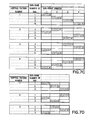
- FIGS. 7A , 7 B, 7 C and 7 D pertain to various examples of hopping patterns
- FIGS. 8A , 8 B and 8 C pertain to the out-band pilot for scheduled (active) users
- FIGS. 9A and 9B pertain to the out-time and out-band pilot for non-scheduled users
- FIGS. 10A and 10B pertain the generation of the hopping patterns
- FIG. 11 shows a sub-frame format and is useful in explaining the roles of SB 1 and SB 2 ;
- FIGS. 12A and 12B are useful in explaining the use of SB 1 as an out-band pilot
- FIGS. 13A and 13B are useful for comparing UE-specific hopping patterns ( FIG. 13A ) and resource-specific hopping patterns ( FIG. 13B );
- FIGS. 14 and 15 pertain to the use of pilot signals in a MIMO system.
- FIG. 16 depicts a flowchart illustrating one non-limiting example of a method for practicing the exemplary embodiments of this invention.
- the considered transmission scheme allows that the scheduling BW covers only adjacent sub-bands.
- channel estimation does not work well, at least for the reason that the division of the in-band pilot and out-band pilot is not balanced.
- the proposed technique suffers from a limited channel tracking capability due to a lack of orthogonal codes.
- the exemplary embodiments of this invention may generally be seen to pertain to the UTRAN LTE UL, and, more specifically, to pilot signal transmission for use with out-band and out-time pilots used for frequency and time domain channel dependent scheduling. Note that the pilot signal transmission technique in accordance with the exemplary embodiments of this invention may be used with all three options listed in FIG. 2 .
- the pilot code (both in-band and out-band) is tied to the used resource, i.e., there is no user-specific pilot. Further, the out-band pilot is transmitted using a predetermined frequency hopping pattern.
- SB 1 is defined as the in-band pilot and is transmitted using code # 1 (the code list may vary from cell to cell).
- the hopping pattern and pilot code allocation for SB 2 are based on the (sub-frame and sub-band) location of the first SB 1 (the first in-band pilot).
- the following is a non-limiting example of a frequency hopping pattern generation for SB 2 .
- L length of the hopping pattern (a semi-static parameter).
- y hopping pattern index ( 1 . . . L).
- One advantage of this approach is that it supports scheduling over non-adjacent sub-bands. This is important not only from a performance point of view, but also from a flexible spectrum usage point of view. Another advantage is that it provides optimized channel estimation performance. Further, the approach outlined above is optimized from a signaling point of view, it provides sufficient tracking capability for channel sounding, and may be used with any of the three options shown in FIG. 2 . In addition, the approach in accordance with the exemplary embodiments of this invention supports the use of a variable length TTI.
- a wireless network 1 is adapted for communication with a UE 10 via a Node B (base station) 12 .
- the network 1 may include a RNC 14 , which may be referred to as a serving RNC (SRNC).
- the UE 10 includes a data processor (DP) 10 A, a memory (MEM) 10 B that stores a program (PROG) 10 C, and a suitable radio frequency (RF) transceiver 10 D for bidirectional wireless communications with the Node B 12 via at least one antenna.
- DP data processor
- MEM memory
- PROG program
- RF radio frequency
- the Node B 12 also includes a DP 12 A, a MEM 12 B that stores a PROG 12 C, and a suitable RF transceiver 12 D.
- the Node B 12 is coupled via a data path 13 to the RNC 14 that also includes a DP 14 A and a MEM 14 B storing an associated PROG 14 C.
- the RNC 14 may be coupled to another RNC (not shown).
- At least one of the PROGs 10 C and 12 C is assumed to include program instructions that, when executed by the associated DP, enable the electronic device to operate in accordance with the exemplary embodiments of this invention, as will be discussed below in greater detail.
- the various embodiments of the UE 10 can include, but are not limited to, cellular phones, personal digital assistants (PDAs) having wireless communication capabilities, portable computers having wireless communication capabilities, image capture devices such as digital cameras having wireless communication capabilities, gaming devices having wireless communication capabilities, music storage and playback appliances having wireless communication capabilities, Internet appliances permitting wireless Internet access and browsing, as well as portable units or terminals that incorporate combinations of such functions.
- PDAs personal digital assistants
- portable computers having wireless communication capabilities
- image capture devices such as digital cameras having wireless communication capabilities
- gaming devices having wireless communication capabilities
- music storage and playback appliances having wireless communication capabilities
- Internet appliances permitting wireless Internet access and browsing, as well as portable units or terminals that incorporate combinations of such functions.
- the exemplary embodiments of this invention may be implemented by computer software executable by the DP 10 A of the UE 10 and the other DPs, or by hardware, or by a combination of software and hardware.
- the MEMs 10 B, 12 B and 14 B may be of any type suitable to the local technical environment and may be implemented using any suitable data storage technology, such as semiconductor-based memory devices, magnetic memory devices and systems, optical memory devices and systems, fixed memory and removable memory, as non-limiting examples.
- the DPs 10 A, 12 A and 14 A may be of any type suitable to the local technical environment, and may include one or more of general purpose computers, special purpose computers, microprocessors, digital signal processors (DSPs) and processors based on a multi-core processor architecture, as non-limiting examples.
- the currently considered approaches for the UTRAN-LTE UL involve scheduling over adjacent sub-bands and utilize an unlimited CQI rate. It can be shown that the use of the currently considered approaches would result in inferior channel estimation performance and a limited channel tracking capability (lack of orthogonal codes), as compared with utilizing aspects of the exemplary embodiments of the invention. Further, the currently proposed approaches employ user-specific pilot codes.
- the use of the exemplary embodiments of this invention provides support for scheduling over non-adjacent sub-bands, enable the use of a limited CQI rate (e.g., 0.5 ms), provide optimized channel estimation and provide adequate channel tracking capability. Further, resource-specific pilot codes are employed, as opposed to user-specific pilot codes.
- the CQI rate is limited to 0.5 ms. In other embodiments, a different CQI rate may be used.
- FIG. 4 shows an example of data allocation in a scheduled UL system for a number of users (users A, B, C, D, E, F and I). Both TDM and FDM principles are used to multiplex different users within the given time and frequency resource.
- User allocation may be based on, as a non-limiting example, the instantaneous channel quality.
- the out-band/out-time pilot is employed.
- FIG. 4 assumes that the CQI is collected every 2 ms, which is of the order of the round-trip delay, and thus a faster CQI is likely not required.
- the overhead that results from the out-band pilot can be maintained at a reasonable level as the rate of the CQI is limited.
- the usage of the orthogonal pilot resources is also maintained at a reasonable level. Note again that pilot transmission approach in accordance with the exemplary embodiments of this invention supports variable length TTI (e.g., one sub-frame and four sub-frames).
- FIG. 5 pertains to transmission of the out-band pilot. It can be appreciated that the gain from channel dependent frequency domain scheduling is improved by also being able to allocate the non-adjacent sub-bands for scheduling. Further, a low PAR is maintained by restricting the allocated BW only for the adjacent sub-bands.
- the hopping patterns for out-band/out-time pilot may be pre-defined, for example.
- FIG. 6 shows various (orthogonal) code resources (e.g., codes 1 - 6 ) associated with sub-frames and sub-bands, and is useful for explaining exemplary rules for pilot transmission. It also shows that the first pilot block (SB 1 ) is always transmitted using the first code of the code list. It may be assumed that the codes are either Cyclic Shifts of a certain CAZAC code, or are orthogonal frequency pin allocations of Distributed FDMA pilot code (CAZAC), as non-limiting examples. SB 1 is generally transmitted using code # 1 (the code list may vary from cell to cell). Note that different codes may be needed with different BW options (cyclic shift approach). SB 1 is reserved for the in-band pilot.
- codes 1 are either Cyclic Shifts of a certain CAZAC code, or are orthogonal frequency pin allocations of Distributed FDMA pilot code (CAZAC), as non-limiting examples.
- SB 1 is generally transmitted using code # 1 (the code list may vary from cell to cell). Note that different codes
- SB 2 is used for the out-band pilot except in the sub-frame and sub-band of the first SB 1 in which SB 2 is also transmitted in-band (this case is shown in FIG. 5 in the first TTI, where it can be observed that both SB 1 and SB 2 are transmitted in-band, as well as in FIG. 13B ).
- Each user in the scheduling group has a predetermined code and hopping pattern for the out-band/out-time pilot, where, in accordance with the exemplary embodiments of this invention, the code and hopping pattern of scheduled users is defined by the allocated resource. Note that unused codes and hopping patterns can be used by the non-active users (those not active during the scheduling period). It should be noted again that resource-specific pilot codes. (both in-band and out-band) are employed, as opposed to user-specific pilot codes. This beneficially removes the need for additional signaling.
- FIGS. 7A , 7 B, 7 C and 7 D illustrate various examples of hopping patterns. Note that different hopping patterns may be generated for different BW allocations, and that the hopping patterns are orthogonal under the same pilot code. It should be appreciated that hopping patterns can be readily generated for different scheduling BW allocations, pilot BW allocations, and also for different CQI rates.
- FIGS. 8A , 8 B and 8 C pertain to the out-band pilot for scheduled (active) users.
- the hopping pattern and pilot code allocation for SB 2 are based on the location of the first SB 1 (in-band pilot).
- the pilot code is selected based on the sub-frame number of the first in-band pilot. For example, when the sub-frame number of the first in-band pilot is # 2 , then code # 2 is selected for SB 2 .
- the hopping pattern is selected based on the sub-band number of the first in-band pilot. For example, when the sub-frame number of the first in-band pilot is # 3 (code # 3 ) and the corresponding sub-band number is # 1 , then the hopping pattern is # 3 .
- a hopping pattern is selected which is based on the first active sub-band (e.g., sub-band # 1 ) during the first active sub-frame (e.g., the third sub-frame).
- R 1st active sub-frame
- FIGS. 9A and 9B pertain to the out-time and out-band pilot for non-scheduled users.
- the unused codes and hopping patterns can be used by the non-active users (i.e., users who are not active during the scheduling period).
- the question then arises as to how best to manage the pilot patterns and pilot codes between the active and non-active user. In one exemplary embodiment of the invention, this can be accomplished by reallocating the free resources among the non-active users separately for each scheduling period, and to signal the allocations to the UEs 10 (as shown in FIG. 9A ).
- a portion of the pilot resources is pre-reserved for certain users, who then utilize the pre-allocated resources when they are not scheduled for data transmission. This approach is shown in FIG. 9B .
- the code list (e.g., order of the utilization) is preferably cell-specific.
- the code list may be signaled, as one non-limiting example, via L3 (Layer 3, Radio Network Layer) signaling. It is beneficial to use different codes as code # 1 in different cells because some of the codes may exhibit better orthogonality under a longer timing difference (resistance against other cell interference).
- the in-band pilot on SB 1 is transmitted using code # 1 .
- the pilot resource of non-active users is signaled to the UE 10 during the resource allocation.
- the resource may be characterized (e.g., signaled) by two parameters: hopping pattern and code.
- the resource is selected from all the available resources, where the resources can be used according to the predetermined list (providing robustness against the inter-cell interference of the pilot signals), and the signaling can be minimized by allocating the fixed resources for given users when they have no data to transmit.
- FIGS. 10A and 10B pertain to the generation of the hopping patterns.
- two input parameters can be used to generate the basic hopping pattern:
- L length of the hopping pattern (a semi-static parameter).
- Y hopping pattern index ( 1 . . . L).
- hopping pattern (z) rem(z ⁇ 1+(y ⁇ 1),L)+1.
- the channel tracking capability may be limited compared to the case where SB 1 can also be used for the out-band pilot for non-active users (discussed below in relation to FIGS. 12A and 12B ). However, this does not present a significant problem since the channel tracking capability is generally very good.
- FIGS. 12A and 12B for a discussion of the use of SB 1 as an out-band pilot, note that if IRC is not used then it is possible to use the orthogonal resources of SB 1 for transmission of an out-band pilot. This extends the channel tracking capability by a factor of two, and provides more freedom for pre-allocation of the pilot resources for non-active users (resulting in reduced signaling).
- the active user has a larger transmit BW than the minimum transmit BW (e.g., 375 kHz)
- the in-band code (SB 1 ) and out-band codes (SB using the transmit BW of 375 kHz) are no longer orthogonal (distributed FDMA-based pilots do not exhibit this type of problem).
- FIGS. 13A and 13B are useful for comparing UE-specific hopping patterns ( FIG. 13A ) and resource-specific hopping patterns with a hopping out-band pilot ( FIG. 13B ).
- the in-band pilot is not matched for the data transmission, additional delay can be required for detection, and problems can be experienced with high Doppler frequency shifts.
- the in-band pilot is always matched to the data transmission in an optimized way.
- FIGS. 14 and 15 pertain to the use of pilot signals in a (possibly) multi-antenna MIMO system.
- the SB 1 of antenna # 1 is transmitted using code # 1 (SIMO) and the SB 1 of antennas # 2 is transmitted using code # 2 .
- SIMO code # 1
- SB 1 of antennas # 2 is transmitted using code # 2 .
- the transmission of the out-band pilot is done similarly as in the case of single antenna transmission, and the hopping patterns and pilot codes of SB 2 are tied to the used resources. Both antennas use the same hopping pattern, and different antennas utilize different pilot codes.
- the same principles apply for both multi-antenna MIMO and Virtual MIMO.
- the CQI rate can be decreased when the system exhausts the orthogonal pilot resources.
- the exemplary embodiments of this invention provide methods, apparatus and computer program products to operate the UE 10 to selectively transmit UL pilot signals during sub-bands and slots, where at least two blocks (block 1 and block 2 ) are reserved for pilot signals, where block 1 is defined as an in-band pilot signal and is transmitted using a first pilot code, and where a frequency hopping pattern and pilot code allocation for block 2 are based on a slot and a sub-band in which a first block 2 is transmitted.
- the UL is a UTRAN-LTE UL.
- block 1 comprises two long blocks (LBs), LB 1 and LB 2 , and block 2 comprises a third long block, LB 3 .
- a method comprises: transmitting uplink pilot signals during sub-bands and slots, wherein at least three blocks (LB 1 , LB 2 and LB 3 ) are reserved for pilot signals, wherein LB 1 and LB 2 comprise in-band pilot signals transmitted using a dedicated pilot code (box 162 ); and transmitting LB 3 using a frequency hopping pattern and pilot code allocation that are based on a slot and a sub-band in which a first LB 3 is transmitted (box 164 ).
- the dedicated pilot code comprises a code in a code list.
- codes in the code list comprise cyclic shifts of a constant amplitude zero autocorrelation (CAZAC) code.
- codes in the code list comprise orthogonal frequency pin allocations of a Distributed FDMA pilot code (constant amplitude zero autocorrelation—CAZAC).
- the dedicated pilot code comprises a first code in a code list.
- LB 3 comprises an out-band pilot except in a slot and sub-band in which a first LB 1 and/or LB 2 is transmitted, wherein in the slot and sub-band in which the first LB 1 and/or LB 2 is transmitted LB 3 is also transmitted in-band.
- each user equipment in a scheduling group has a predetermined code and hopping pattern for the out-band pilot, wherein the code and hopping pattern of a scheduled user equipment are defined by an allocated resource.
- unused codes and hopping patterns are useable by non-active user equipments.
- the uplink comprises a universal terrestrial radio access network-long term evolution (UTRAN-LTE) uplink, and wherein a CQI rate is constrained.
- UTRAN universal terrestrial radio access network-long term evolution
- a user equipment comprises: a data processor; and a wireless transceiver configured to transmit uplink pilot signals during sub-bands and slots, wherein at least three blocks (LB 1 , LB 2 and LB 3 ) are reserved for pilot signals, wherein LB 1 and LB 2 comprise in-band pilot signals transmitted using a dedicated pilot code, and to transmit LB 3 using a frequency hopping pattern and pilot code allocation that are based on a slot and a sub-band in which a first LB 3 is transmitted.
- a user equipment comprises: processing means; and transmitting means for transmitting uplink pilot signals during sub-bands and slots, wherein at least three blocks (LB 1 , LB 2 and LB 3 ) are reserved for pilot signals, wherein LB 1 and LB 2 comprise in-band pilot signals transmitted using a dedicated pilot code, and for transmitting LB 3 using a frequency hopping pattern and pilot code allocation that are based on a slot and a sub-band in which a first LB 3 is transmitted.
- the means for processing comprises a data processor and the transmitting means comprises at least one transmitter or at least one transceiver.
- exemplary embodiments of the invention may be implemented as a computer program product comprising program instructions embodied on a tangible computer-readable medium. Execution of the program instructions results in operations comprising steps of utilizing the exemplary embodiments or steps of the method.
- the various exemplary embodiments may be implemented in hardware or special purpose circuits, software, logic or any combination thereof.
- some aspects may be implemented in hardware, while other aspects may be implemented in firmware or software which may be executed by a controller, microprocessor or other computing device, although the invention is not limited thereto.
- firmware or software which may be executed by a controller, microprocessor or other computing device, although the invention is not limited thereto.
- While various aspects of the exemplary embodiments of this invention may be illustrated and described as block diagrams, sub-frame/sub-band diagrams, or by using some other pictorial representation, it is well understood that these blocks, apparatus, systems, techniques or methods described herein may be implemented in, as non-limiting examples, hardware, software, firmware, special purpose circuits or logic, general purpose hardware or controller or other computing devices, or some combination thereof.
- the exemplary embodiments of the inventions may be practiced in various components such as integrated circuit modules.
- the design of integrated circuits is by and large a highly automated process. Complex and powerful software tools are available for converting a logic level design into a semiconductor circuit design ready to be etched and formed on a semiconductor substrate.
- Programs such as those provided by Synopsys, Inc. of Mountain View, Calif. and Cadence Design, of San Jose, Calif. automatically route conductors and locate components on a semiconductor chip using well established rules of design as well as libraries of pre-stored design modules.
- the resultant design in a standardized electronic format (e.g., Opus, GDSII, or the like) may be transmitted to a semiconductor fabrication facility or “fab” for fabrication.
- the use of the exemplary embodiments of this invention is not limited to only the specific numbers of sub-band, sub-frames and codes that were discussed above and shown in the drawings. Further by example, the use of the exemplary embodiments of this invention is not limited to only the use of two SBs, as more than two could be employed with suitable modifications to the foregoing exemplary embodiments.
- the exemplary embodiments of the invention are not limited to only this one type of system.
- the exemplary embodiments of the invention may be utilized in conjunction with long blocks (LBs), sub-bands and slots.
- the SBs are replaced by LBs.
- One sub-frame includes two slots, each slot having a length of 0.5 ms, for example.
- Each subframe includes two pilot LBs (LB 1 and LB 2 ; e.g., for a demodulation reference signal (RS)) and may include an optional third LB (LB 3 ) which may also be referred to as a sounding LB.
- LB 3 is used for transmitting out-band/out-time reference signals (RS).
- LB 3 may be periodic and also may be subject to frequency hopping (FH) as described in greater detail above.
- the signaling of LB 3 may be performed, for example, using radio link control (RLC) signaling without explicitly signaling the FH pattern.
- RLC radio link control
Abstract
Description
X(R)=B.
Claims (25)
X(R)=B,
X(R)=B,
X(R)=B,
X(R)=B,
Priority Applications (1)
| Application Number | Priority Date | Filing Date | Title |
|---|---|---|---|
| US11/789,731 US7860150B2 (en) | 2006-04-24 | 2007-04-24 | Apparatus, method, and computer program product providing improved uplink pilot transmission schemes |
Applications Claiming Priority (2)
| Application Number | Priority Date | Filing Date | Title |
|---|---|---|---|
| US79461106P | 2006-04-24 | 2006-04-24 | |
| US11/789,731 US7860150B2 (en) | 2006-04-24 | 2007-04-24 | Apparatus, method, and computer program product providing improved uplink pilot transmission schemes |
Publications (2)
| Publication Number | Publication Date |
|---|---|
| US20070248147A1 US20070248147A1 (en) | 2007-10-25 |
| US7860150B2 true US7860150B2 (en) | 2010-12-28 |
Family
ID=38619472
Family Applications (1)
| Application Number | Title | Priority Date | Filing Date |
|---|---|---|---|
| US11/789,731 Expired - Fee Related US7860150B2 (en) | 2006-04-24 | 2007-04-24 | Apparatus, method, and computer program product providing improved uplink pilot transmission schemes |
Country Status (1)
| Country | Link |
|---|---|
| US (1) | US7860150B2 (en) |
Cited By (8)
| Publication number | Priority date | Publication date | Assignee | Title |
|---|---|---|---|---|
| US20100067512A1 (en) * | 2008-09-17 | 2010-03-18 | Samsung Electronics Co., Ltd. | Uplink transmit diversity schemes with 4 antenna ports |
| US20100157936A1 (en) * | 2006-08-15 | 2010-06-24 | Texas Instruments Incorporated | Uplink Reference Signal for Time and Frequency Scheduling of Transmissions |
| US20110149896A1 (en) * | 2006-08-22 | 2011-06-23 | Ntt Docomo, Inc. | Base station and mobile station |
| US20110194527A1 (en) * | 2010-02-11 | 2011-08-11 | Qualcomm Incorporated | Frequency and time domain range expansion |
| US20120020387A1 (en) * | 2007-02-05 | 2012-01-26 | Nec Corporation | Frequency hopping |
| US20160056937A1 (en) * | 2006-02-07 | 2016-02-25 | Lg Electronics Inc. | Method for transmitting pilot for multiple carrier system |
| US20160204911A1 (en) * | 2006-04-25 | 2016-07-14 | Nec Corporation | Pilot signal transmission method and radio communication apparatus |
| US20180131482A1 (en) * | 2016-11-04 | 2018-05-10 | Spreadtrum Communications (Shanghai) Co., Ltd. | Cross-subband or cross-carrier scheduling method, base station and user equipment |
Families Citing this family (16)
| Publication number | Priority date | Publication date | Assignee | Title |
|---|---|---|---|---|
| WO2008023349A2 (en) * | 2006-08-23 | 2008-02-28 | Nokia Corporation | Pilot design for long term evolution uplink multi-input multi-output antenna system |
| US8213483B2 (en) * | 2007-02-06 | 2012-07-03 | Qualcomm Incorporated | Hopping structures for broadband pilot signals |
| US8213943B2 (en) | 2007-05-02 | 2012-07-03 | Qualcomm Incorporated | Constrained hopping of DL reference signals |
| US8219030B2 (en) * | 2007-06-20 | 2012-07-10 | Qualcomm Incorporated | Adaptive distributed frequency planning |
| US9496918B2 (en) | 2007-08-08 | 2016-11-15 | Telefonaktiebolaget Lm Ericsson (Publ) | Multicarrier communication system employing explicit frequency hopping |
| BRPI0814942B1 (en) * | 2007-08-08 | 2020-09-15 | Telefonaktiebolaget Lm Ericsson (Publ) | METHOD FOR PROGRAMMING TRANSMISSIONS IN A MOBILE COMMUNICATION SYSTEM, AND, PROGRAMMER IN A MOBILE COMMUNICATION SYSTEM TO PROGRAM TRANSMISSIONS FOR A PLURALITY OF MOBILE DEVICES |
| JP5539200B2 (en) * | 2007-08-10 | 2014-07-02 | アルカテル−ルーセント | Mobile user resource allocation method and resource allocation scheduler using the same |
| EP2228934B1 (en) * | 2008-01-04 | 2019-03-06 | Sun Patent Trust | Radio communication terminal device and radio transmission method |
| US8774103B2 (en) * | 2008-03-26 | 2014-07-08 | Broadcom Corporation | Selecting uplink sounding sub-carriers |
| US20110026482A1 (en) * | 2008-03-27 | 2011-02-03 | Postdata Co., Ltd. | Method and apparatus for pilot signal transmission |
| CN101610101B (en) * | 2008-06-16 | 2013-02-27 | 中兴通讯股份有限公司 | Frequency hopping method for downlink special pilot frequencies |
| WO2010046202A1 (en) * | 2008-10-20 | 2010-04-29 | Nokia Siemens Networks Oy | Sounding channel apparatus and method |
| US8605644B2 (en) * | 2009-02-12 | 2013-12-10 | Nokia Siemens Networks Oy | Transmission power control for sounding signal for wireless networks |
| EP2448143B1 (en) | 2009-06-26 | 2019-02-27 | LG Electronics Inc. | Method and apparatus for transmitting reference signals in uplink multiple input multiple output (mimo) transmission |
| JP5592936B2 (en) * | 2010-03-29 | 2014-09-17 | パナソニック インテレクチュアル プロパティ コーポレーション オブ アメリカ | Terminal apparatus, base station apparatus, pilot transmission method, and propagation path estimation method |
| TWI597993B (en) * | 2015-12-29 | 2017-09-01 | 財團法人工業技術研究院 | Method for schduling pilot signal, control node and wireless device |
Citations (5)
| Publication number | Priority date | Publication date | Assignee | Title |
|---|---|---|---|---|
| US20060176859A1 (en) * | 2005-02-04 | 2006-08-10 | Samsung Electronics Co., Ltd. | Method and apparatus for transmitting/receiving data in a cellular communication system |
| US7272162B2 (en) * | 2000-10-24 | 2007-09-18 | Mitsubishi Denki Kabushiki Kaisha | Transmitter and receiver for spread-spectrum communication system, and modulation and demodulation methods thereof |
| US20080090528A1 (en) * | 2006-07-07 | 2008-04-17 | Malladi Durga P | Method and apparatus for sending data and control information in a wireless communication system |
| US7421041B2 (en) * | 2004-03-01 | 2008-09-02 | Qualcomm, Incorporated | Iterative channel and interference estimation and decoding |
| US7660367B2 (en) * | 2003-04-04 | 2010-02-09 | Panasonic Corporation | Base station using a multicarrier communication band divided into a plurality of blocks |
-
2007
- 2007-04-24 US US11/789,731 patent/US7860150B2/en not_active Expired - Fee Related
Patent Citations (5)
| Publication number | Priority date | Publication date | Assignee | Title |
|---|---|---|---|---|
| US7272162B2 (en) * | 2000-10-24 | 2007-09-18 | Mitsubishi Denki Kabushiki Kaisha | Transmitter and receiver for spread-spectrum communication system, and modulation and demodulation methods thereof |
| US7660367B2 (en) * | 2003-04-04 | 2010-02-09 | Panasonic Corporation | Base station using a multicarrier communication band divided into a plurality of blocks |
| US7421041B2 (en) * | 2004-03-01 | 2008-09-02 | Qualcomm, Incorporated | Iterative channel and interference estimation and decoding |
| US20060176859A1 (en) * | 2005-02-04 | 2006-08-10 | Samsung Electronics Co., Ltd. | Method and apparatus for transmitting/receiving data in a cellular communication system |
| US20080090528A1 (en) * | 2006-07-07 | 2008-04-17 | Malladi Durga P | Method and apparatus for sending data and control information in a wireless communication system |
Non-Patent Citations (17)
| Title |
|---|
| 3GPP TR 25.814, V1.2.2, "3rd Generation Partnership Project; Technical Specification Group Radio Access Network; Physical Layer Aspects for Evolved UTRA", (Release 7) (Mar. 2006). |
| 3GPP TR 25.814, V7.1.0, "3rd Generation Partnership Project; Technical Specification Group Radio Access Network; Physical layer aspects for evolved Universal Terrestrial Radio Access (UTRA)", (Release 7) (Sep. 2006). |
| 3GPP TS 36.211, V1.0.0, "3rd Generation Partnership Project; Technical Specification Group Radio Access Network; Physical Channels and Modulation", (Release 8) (Mar. 2007). |
| 3GPP TSG-RAN WG1 Meeting #44bis, R1-060784, "Orthogonal Pilot channel Structure for E-UTRA Uplink", NTT DoCoMo, Fujitsu, Mitsubishi Electric, NEC . . . ,Athens, Greece, Mar. 27-31, 2006. |
| 3GPP TSG-RAN WG1 Meeting #44bis, R1-060785, "L1/L2 Control Channel Structure for E-UTRA Uplink", NTT CoCoMo, Fujitsu, Mitsubishi Electric . . . , Athens, Greece, Mar. 27-31, 2006. |
| 3GPP TSG-RAN WG1 Meeting #44bis, R1-060787, "Frequency Domain Channel-Dependent Scheduling with Adaptive Transmission Bandwidth of Pilot Channel for CQI Measurement for E-UTRA Uplink", NTT DoCoMo,, Fujitsu, Mitsubishi Electric . . . , Athens, Greece, Mar. 27-31, 2006. |
| 3GPP TSG-RAN WG1 Meeting #44bis, R1-060818, "Reference Signal Structure for EUTRA Uplink", Samsung, Athens, Greece, Mar. 27-31, 2006. |
| 3GPP TSG-RAN WG1 Meeting #44bis, R1-060819, "L1/L2 Control signaling Multiplexing in Evolved UTRA Uplink", Samsung, Athens, Greece, Mar. 27-31, 2006. |
| 3GPP TSG-RAN WG1 Meeting #44bis, R1-060831, "Considerations on uplink pilot design using CAZAC", NEC Group, Athens, Greece, Mar. 27-31, 2006. |
| 3GPP TSG-RAN WG1 Meeting #44bis, R1-060847, "Considerations on Pilot Design for the LTE Uplink", Freescale Semiconductor, Inc., Athens, Greece, Mar. 27-31, 2006. |
| 3GPP TSG-RAN WG1 Meeting #44bis, R1-060879, "Performance Comparison of Pilot/Reference Signal Structures for E-UTRA Uplink SC-FDMA", Agenda item: 10.2.1, Motorola, Mar. 27-31, 2006. |
| 3GPP TSG-RAN WG1 Meeting #44bis, R1-060907, "Sounding channel for UL channel-dependent scheduling", Nortel, Athens, Greece, Mar. 27-31, 2006. |
| 3GPP TSG-RAN WG1 Meeting #44bis, R1-060919, "Uplink pilot for channel quality measurement", LG Electronics, Athens, Greece, Mar. 27-31, 2006. |
| 3GPP TSG-RAN WG1 Meeting #44bis, R1-060925, "Comparison of Proposed Uplink Pilot Structures For SC-OFDMA", Agenda Item: 10.2.1, Texas Instruments, Athens, Greece, Mar. 27-31, 2006. |
| 3GPP TSG-RAN WG1 Meeting #44bis, R1-060972, "Pilot design for E-UTRA uplink", RITT, Athens, Greece, Mar. 27-31, 2006. |
| 3GPP TSG-RAN WG1 Meeting #44bis, R1-060985, "Impacts of Uplink FDM Pilot Density", Huawei, Athens, Greece, Mar. 27-31, 2006. |
| 3GPP TSG-RAN WG1 Meeting #44bis, R1-061094, "Text proposa on Orthogonal Pilot Channel Structure for E-UTRA Uplink", NTT DoCoMO, Panasonic, Ericsson, Fujitsu . . . , Athens, Greece, Mar. 27-31, 2006. |
Cited By (31)
| Publication number | Priority date | Publication date | Assignee | Title |
|---|---|---|---|---|
| US20160056937A1 (en) * | 2006-02-07 | 2016-02-25 | Lg Electronics Inc. | Method for transmitting pilot for multiple carrier system |
| US10270571B2 (en) | 2006-02-07 | 2019-04-23 | Lg Electronics Inc. | Method for transmitting pilot for multiple carrier system |
| US9705651B2 (en) * | 2006-02-07 | 2017-07-11 | Lg Electronics Inc. | Method for transmitting pilot for multiple carrier system |
| US20160204911A1 (en) * | 2006-04-25 | 2016-07-14 | Nec Corporation | Pilot signal transmission method and radio communication apparatus |
| US9735938B2 (en) * | 2006-04-25 | 2017-08-15 | Nec Corporation | Pilot signal transmission method and radio communication apparatus |
| US20100157936A1 (en) * | 2006-08-15 | 2010-06-24 | Texas Instruments Incorporated | Uplink Reference Signal for Time and Frequency Scheduling of Transmissions |
| US20110149896A1 (en) * | 2006-08-22 | 2011-06-23 | Ntt Docomo, Inc. | Base station and mobile station |
| US8000296B2 (en) * | 2006-08-22 | 2011-08-16 | Ntt Docomo, Inc. | Base station and mobile station |
| US10530419B2 (en) | 2007-02-05 | 2020-01-07 | Nec Corporation | Frequency hopping |
| US8774250B2 (en) | 2007-02-05 | 2014-07-08 | Nec Corporation | Frequency hopping |
| US11863228B2 (en) | 2007-02-05 | 2024-01-02 | Nec Corporation | Frequency hopping |
| US8971377B2 (en) | 2007-02-05 | 2015-03-03 | Nec Corporation | Frequency hopping |
| US8982925B2 (en) | 2007-02-05 | 2015-03-17 | Nec Corporation | Frequency hopping |
| US11374617B2 (en) | 2007-02-05 | 2022-06-28 | Nec Corporation | Frequency hopping |
| US8891587B2 (en) | 2007-02-05 | 2014-11-18 | Nec Corporation | Frequency hopping |
| US9584269B2 (en) | 2007-02-05 | 2017-02-28 | Nec Corporation | Frequency hopping |
| US9584270B2 (en) | 2007-02-05 | 2017-02-28 | Nec Corporation | Frequency hopping |
| US10855330B2 (en) | 2007-02-05 | 2020-12-01 | Nec Corporation | Frequency hopping |
| AU2012203140B2 (en) * | 2007-02-05 | 2013-06-20 | Nec Corporation | Frequency hopping technique for EUTRA uplink |
| US11251831B2 (en) | 2007-02-05 | 2022-02-15 | Nec Corporation | Frequency hopping |
| US10027373B2 (en) | 2007-02-05 | 2018-07-17 | Nec Corporation | Frequency hopping |
| US8184672B2 (en) * | 2007-02-05 | 2012-05-22 | Nec Corporation | Frequency hopping |
| US20120020387A1 (en) * | 2007-02-05 | 2012-01-26 | Nec Corporation | Frequency hopping |
| US10554250B2 (en) | 2007-02-05 | 2020-02-04 | Nec Corporation | Frequency hopping |
| US10833726B2 (en) | 2007-02-05 | 2020-11-10 | Nec Corporation | Frequency hopping |
| US10886967B2 (en) | 2007-02-05 | 2021-01-05 | Nec Corporation | Frequency hopping |
| US20100067512A1 (en) * | 2008-09-17 | 2010-03-18 | Samsung Electronics Co., Ltd. | Uplink transmit diversity schemes with 4 antenna ports |
| US20110194527A1 (en) * | 2010-02-11 | 2011-08-11 | Qualcomm Incorporated | Frequency and time domain range expansion |
| US8953507B2 (en) * | 2010-02-11 | 2015-02-10 | Qualcomm Incorporated | Frequency and time domain range expansion |
| US10855414B2 (en) * | 2016-11-04 | 2020-12-01 | Spreadtrum Communications (Shanghai) Co., Ltd. | Cross-subband or cross-carrier scheduling method, base station and user equipment |
| US20180131482A1 (en) * | 2016-11-04 | 2018-05-10 | Spreadtrum Communications (Shanghai) Co., Ltd. | Cross-subband or cross-carrier scheduling method, base station and user equipment |
Also Published As
| Publication number | Publication date |
|---|---|
| US20070248147A1 (en) | 2007-10-25 |
Similar Documents
| Publication | Publication Date | Title |
|---|---|---|
| US7860150B2 (en) | Apparatus, method, and computer program product providing improved uplink pilot transmission schemes | |
| US20230107098A1 (en) | Terminal and communication method | |
| RU2463714C2 (en) | Method, apparatus, system and related computer program product for resource allocation | |
| US8644238B2 (en) | Demodulation reference signals in a communication system | |
| KR101513196B1 (en) | Sequence hopping in sc-fdma communications systems | |
| CN102171981B (en) | Method of transmitting control signal in wireless communication system | |
| US8452295B2 (en) | Apparatus, method, and computer program product providing persistent uplink and downlink resource allocation | |
| US9642119B2 (en) | Resource allocation in a wireless communication system | |
| US20130182674A1 (en) | Transmission of Reference Signals | |
| CN111465110B (en) | Data transmission method and terminal equipment | |
| CN113517967B (en) | Method for determining Channel State Information (CSI) report and communication equipment | |
| JP2010519879A (en) | Method for transmitting control signals in a wireless communication system | |
| CN114844608A (en) | Multi-transmission-node transmission method and communication device | |
| US20080232486A1 (en) | Systems and methods for extending zadoff-chu sequences to a non-prime number length to minimize average correlation | |
| WO2018126787A1 (en) | Uplink authorization-free user activation detection method, device, and base station | |
| CN110972303A (en) | Communication method, device, equipment, system and storage medium | |
| US20100177834A1 (en) | Systems and methods for improving reference signals for spatially multiplexed cellular systems | |
| US20190327059A1 (en) | Reference signal sending/receiving method, terminal device, and network device | |
| KR20180121231A (en) | Apparatus and method for supporting different services in wireless communication system | |
| US20070201408A1 (en) | Apparatus, method and computer program product providing a transport format that is compatible with another transport format that uses spreading codes | |
| CN107370586B (en) | Channel transmission method and device | |
| US11184904B2 (en) | Cross-standard scheduling method and base station | |
| EP3764711B1 (en) | Resource allocation method and apparatus | |
| WO2011079454A1 (en) | Overlapping resource signaling via code switching | |
| CN113453350A (en) | Scheduling method and device of physical downlink control channel |
Legal Events
| Date | Code | Title | Description |
|---|---|---|---|
| AS | Assignment |
Owner name: NOKIA CORPORATION, FINLAND Free format text: ASSIGNMENT OF ASSIGNORS INTEREST;ASSIGNORS:TIIROLA, ESA;PAJUKOSKI, KARI;REEL/FRAME:019500/0952 Effective date: 20070529 |
|
| FEPP | Fee payment procedure |
Free format text: PAYOR NUMBER ASSIGNED (ORIGINAL EVENT CODE: ASPN); ENTITY STATUS OF PATENT OWNER: LARGE ENTITY |
|
| AS | Assignment |
Owner name: RPX CORPORATION, CALIFORNIA Free format text: ASSIGNMENT OF ASSIGNORS INTEREST;ASSIGNOR:NOKIA CORPORATION;REEL/FRAME:028323/0196 Effective date: 20120531 |
|
| FEPP | Fee payment procedure |
Free format text: PAYER NUMBER DE-ASSIGNED (ORIGINAL EVENT CODE: RMPN); ENTITY STATUS OF PATENT OWNER: LARGE ENTITY Free format text: PAYOR NUMBER ASSIGNED (ORIGINAL EVENT CODE: ASPN); ENTITY STATUS OF PATENT OWNER: LARGE ENTITY |
|
| FPAY | Fee payment |
Year of fee payment: 4 |
|
| AS | Assignment |
Owner name: JEFFERIES FINANCE LLC, NEW YORK Free format text: SECURITY INTEREST;ASSIGNOR:RPX CORPORATION;REEL/FRAME:046486/0433 Effective date: 20180619 |
|
| FEPP | Fee payment procedure |
Free format text: MAINTENANCE FEE REMINDER MAILED (ORIGINAL EVENT CODE: REM.); ENTITY STATUS OF PATENT OWNER: LARGE ENTITY |
|
| LAPS | Lapse for failure to pay maintenance fees |
Free format text: PATENT EXPIRED FOR FAILURE TO PAY MAINTENANCE FEES (ORIGINAL EVENT CODE: EXP.); ENTITY STATUS OF PATENT OWNER: LARGE ENTITY |
|
| STCH | Information on status: patent discontinuation |
Free format text: PATENT EXPIRED DUE TO NONPAYMENT OF MAINTENANCE FEES UNDER 37 CFR 1.362 |
|
| FP | Lapsed due to failure to pay maintenance fee |
Effective date: 20181228 |
|
| AS | Assignment |
Owner name: RPX CORPORATION, CALIFORNIA Free format text: RELEASE BY SECURED PARTY;ASSIGNOR:JEFFERIES FINANCE LLC;REEL/FRAME:054486/0422 Effective date: 20201023 |