US7857357B2 - Reinforced pipe fitting with eccentric flow path - Google Patents
Reinforced pipe fitting with eccentric flow path Download PDFInfo
- Publication number
- US7857357B2 US7857357B2 US12/103,874 US10387408A US7857357B2 US 7857357 B2 US7857357 B2 US 7857357B2 US 10387408 A US10387408 A US 10387408A US 7857357 B2 US7857357 B2 US 7857357B2
- Authority
- US
- United States
- Prior art keywords
- section
- crotch
- point
- longitudinal axis
- area
- Prior art date
- Legal status (The legal status is an assumption and is not a legal conclusion. Google has not performed a legal analysis and makes no representation as to the accuracy of the status listed.)
- Active, expires
Links
- 239000000463 material Substances 0.000 description 15
- 230000008901 benefit Effects 0.000 description 4
- 239000012530 fluid Substances 0.000 description 4
- 229910052755 nonmetal Inorganic materials 0.000 description 3
- 125000004122 cyclic group Chemical group 0.000 description 2
- 239000000203 mixture Substances 0.000 description 2
- 230000006978 adaptation Effects 0.000 description 1
- 230000007774 longterm Effects 0.000 description 1
- 238000002156 mixing Methods 0.000 description 1
- 238000012986 modification Methods 0.000 description 1
- 230000004048 modification Effects 0.000 description 1
- 230000008719 thickening Effects 0.000 description 1
Images


Classifications
-
- F—MECHANICAL ENGINEERING; LIGHTING; HEATING; WEAPONS; BLASTING
- F16—ENGINEERING ELEMENTS AND UNITS; GENERAL MEASURES FOR PRODUCING AND MAINTAINING EFFECTIVE FUNCTIONING OF MACHINES OR INSTALLATIONS; THERMAL INSULATION IN GENERAL
- F16L—PIPES; JOINTS OR FITTINGS FOR PIPES; SUPPORTS FOR PIPES, CABLES OR PROTECTIVE TUBING; MEANS FOR THERMAL INSULATION IN GENERAL
- F16L43/00—Bends; Siphons
- F16L43/008—Bends; Siphons made from plastic material
Definitions
- This invention relates generally to non-metal pipe fittings, such as tees, ells and 45° bends, capable of changing the direction of fluids flowing through such pipe fittings. More specifically, the invention is directed to such pipe fittings wherein the crotch or crotches within such fittings are reinforced.
- the crotch (or crotches) of non-metal pipe fittings such as tees, ells, 45° bends, crosses, wyes and double wyes is a common failure point when such fittings are subjected to cyclic pressure conditions.
- the crotch is acted on by the pressurized fluid and is induced towards becoming round or inverted.
- the invention satisfies this need.
- the invention is a reinforced pipe fitting having a cylindrical first section and a cylindrical second section. Each section has side walls and an open end which is circular in cross-section.
- the first section has a first longitudinal axis and the second section has a second longitudinal axis.
- the second longitudinal axis intersects the first longitudinal axis at an angle ⁇ less than 180°.
- the side walls of the first section intersect the side walls of the second section at a crotch point disposed within the plane defined by the first and second longitudinal axes.
- the first section defines a first section crotch area pipe stop having a first section crotch area pipe stop proximal portion disposed proximate to the crotch point and a first section crotch area pipe stop distal portion disposed opposite the first section crotch area pipe section proximal portion.
- the average thickness of the first section crotch area pipe stop proximal portion disposed 15° to either side of the plane defined by the first and second longitudinal axes is greater by about 15% than the average thickness of the first section crotch area pipe stop distal portion disposed 15° to either side of the plane defined by the first and second longitudinal axes.
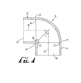
- FIG. 1 is an end view of a pipe fitting of the prior art
- FIG. 2 is a cross-sectional side view of the pipe fitting illustrated in FIG. 1 ;
- FIG. 3A is a first end view of a pipe fitting having features of the invention.
- FIG. 3B is a second end view of the pipe fitting illustrated in FIG. 3A ;
- FIG. 4 is a cross-sectional side view of the pipe fitting illustrated in FIGS. 3A and 3B ;
- FIG. 5 is a detail cross-sectional side view of the pipe fitting illustrated in FIG. 5 ;
- FIG. 6A is a third end view of a pipe fitting having features of the invention.
- FIG. 6B is a fourth end view of the pipe fitting illustrated in FIG. 3A ;
- FIG. 7 is a cross-sectional side view of the pipe fitting illustrated in FIGS. 6A and 6B ;
- FIG. 8 is a cross-sectional side view of the pipe fitting illustrated in FIGS. 6A and 6B , showing the pipe fitting in combination with a pipe section.
- the invention is directed to a reinforced pipe fitting 10 having a cylindrical first section 12 and a cylindrical second section 14 .
- the pipe fitting 10 is typically a tee, an ell, a 45° bend, a cross, a wye or a double wye.
- Each section of the reinforced pipe fitting 10 comprises side walls 16 and an open end 18 .
- Each open end 18 is circular in cross-section.
- the side walls 16 of the first section 12 are joined in fluid tight communication to the side walls 16 of the second section 14 .
- the first section 12 has a first longitudinal axis 20 and the second section 14 has a second longitudinal axis 22 .
- the second longitudinal axis 22 intersects the first longitudinal axis 20 at an angle ⁇ which is less than 180°, and is typically between about 90° and about 180°.
- the side walls 16 of the first section 12 intersect the side walls 16 of the second section 14 at a crotch point 24 disposed within the plane 25 defined by the first and second longitudinal axes 20 and 22 .
- the first section 12 defines a first section crotch area pipe stop 26 having a first section crotch area pipe stop proximal portion 28 disposed proximate to the crotch point 24 and a first section crotch area pipe stop distal portion 30 disposed opposite the first section crotch area pipe stop proximal portion 28 .
- the average thickness t p of the first section crotch area pipe stop proximal portion 28 disposed 15° to either side of the plane 25 defined by the first and second longitudinal axes 20 and 22 is greater by about 15% than the average thickness t d of the first section crotch area pipe stop distal portion 30 disposed 15° to either side of the plane 25 defined by the first and second longitudinal axes 20 and 22 .
- the second section 14 of the reinforced pipe fitting of the invention 10 defines a second section crotch area pipe stop 32 having a second section crotch area pipe stop proximal portion 34 disposed proximate to the crotch point 24 and a second section crotch area pipe stop distal portion 36 disposed opposite the second section crotch area pipe stop proximal portion 32 .
- the average thickness t p of the second section crotch area pipe stop proximal portion 34 disposed 15° to either side of the plane 25 defined by the first and second longitudinal axes 20 and 22 is greater by about 15% than the average thickness t d of the section crotch area pipe stop distal portion 36 disposed 15° to either side of the plane 25 defined by the first and second longitudinal axes 20 and 22 .
- the thicknesses t p of both the proximal portions 28 and 34 of the first section crotch area and second section crotch area pipe stops 26 and 32 disposed precisely within the plane 25 defined by the first and second longitudinal axes 20 and 22 are greater than about 20% of the thicknesses t d of the distal portions 30 and 36 of the first section and second section crotch area pipe stops 26 and 32 within the plane 25 defined by the first and second longitudinal axes 20 and 22 .
- the purpose of the thickening of the pipe stops 26 and 32 in the crotch area is to add strength to the critical crotch area without adding unnecessary material, as well as to gain the benefit of adding material to the inside of the fitting 10 instead of to the outside of the fitting 10 .
- the cross-section of the cylindrical first section 12 within the plane defined by the face of the first crotch area pipe stop 26 is a first crotch point open area 38 having an eccentric periphery 40 .
- the cross -section of the cylindrical second section 14 within the plane defined by the face of the second crotch area pipe stop 32 is a second pipe stop open area 42 having an eccentric periphery 40 .
- eccentric periphery 40 can comprise a major circular portion 44 and a non-circular portion 46 .
- major circular portion as used in this application means a curve spanning at least about 120° of arc wherein all points on the curve are equidistant from a single point. Typically, that single point coincides with the longitudinal axis 20 or 22 of the respective cylindrical section 12 or 14 .
- non-circular portion as used in this application means a curve wherein all points on the curve are not equidistant from a single point.
- non-circular portions include, but are not limited to, ellipsis, portions of circles having several different radii, portions of circles having the same radii but different centers, and pluralities of short straight lines.
- the non-circular portion 46 is an elliptical portion.
- the invention is contrasted with conventional pipe fittings 100 of the prior art as illustrated in FIGS. 1 and 2 , wherein the cross-section of each flow path 101 in such fittings has a wholly circular shape.
- the non-circular non -circular portion 46 of the periphery 40 of the first crotch point open area 38 is disposed most proximate to the crotch point 24 .
- the width of the first crotch point open area 38 measured along a first line segment 48 running between a point most proximate to the crotch point 24 , through the first longitudinal axis 20 , and to a point on the opposite wall of the first section 12 is shorter than the width of the first crotch point open area 38 measured along a second line segment 50 disposed perpendicular to the first line segment 48 and running between opposite sides of the cylindrical first crotch point open area 38 and passing through the first longitudinal axis 20 .
- the non-circular portion 46 of the periphery 40 of the first crotch point open area 38 has a midpoint 52 , a first end point 54 and an opposed second end point 56 .
- the midpoint 52 of the periphery 40 of the non-circular portion 46 of the first crotch point open area 38 is disposed at the point along the periphery 40 of the first crotch point open area 38 most proximate to the crotch point 24 .
- An angle ⁇ is defined between a first ray 58 passing through the first end point 54 of the non-circular portion 46 of the first crotch point open area 38 and the first longitudinal axis 20 and a second ray 60 passing through the second end point 56 of the non-circular portion 46 of the first crotch point open area 38 and the first longitudinal axis 20 .
- Such angle ⁇ is typically between about 45° and about 180°, more typically between about 60° and about 120°, and most typically between about 80° and about 100°, such as about 90°.
- the ratio of the length of the first line segment 48 to the length of the second line segment 50 is typically between about 0.75 and about 0.98.
- the non-circular portion 46 of the periphery 40 of the second crotch point open area 42 is disposed most proximate to the crotch point 24 . Accordingly, the width of the second crotch point open area 42 , measured along a third line segment 62 running between a point most proximate to the crotch point 24 , through the second longitudinal axis 22 , and to a point on the opposite wall of the second section 14 , is shorter than the width of the second crotch point open area 42 measured along a fourth line segment 64 disposed perpendicular to the third line segment 54 and running between opposite sides of the cylindrical second crotch point open area 42 and passing through the second longitudinal axis 22 .
- the non-circular portion 46 of the periphery 40 of the second crotch point open area 42 has a midpoint 66 , a first end point 68 and an opposed second end point 70 .
- the midpoint 66 of the periphery 40 of the second crotch point open area 42 is disposed at the point along the periphery 40 of the second crotch point open area 42 most proximate to the crotch point 24 .
- An angle ⁇ is defined between a third ray 72 passing through the first end point 68 of the non-circular portion 46 of the periphery 40 of the second crotch point open area 42 and the second longitudinal axis 22 and a fourth ray 74 passing through the second end point 70 of the non-circular portion 46 of the periphery 40 of the second crotch point open area 42 and the second longitudinal axis 22 .
- Such angle ⁇ is typically between about 45° and about 180°, more typically between about 60° and about 120°, and most typically between about 80° and about 100°, such as about 90°.
- the ratio of the length of the third line segment 62 to the length of the fourth line segment 64 is typically between about 0.75 and about 0.98.
- FIG. 8 illustrates a combination wherein the reinforced pipe fitting of the invention 10 is combined with a first pipe section 76 having a first pipe section end 78 and a second pipe section 80 having a first pipe section end 82 .
- Each first pipe section end 78 and 82 has an outside diameter, an inside diameter and a wall thickness t w .
- the first section crotch area pipe stop proximal portion 28 of the reinforced pipe fitting 10 typically has a thickness t p between about 50% and about 110% of the wall thickness t w of the first wall section end 78 of the first pipe section 76
- the second section crotch area pipe stop proximal portion 34 has a thickness between about 50% and about 110% of the wall thickness t w of the first pipe section end 82 of the second pipe section 80 .
- material is added to the most critical area and nothing is added to areas that cannot benefit from additional material.
- the amount of material is typically determined by making the inside wall of the thickest section flush with the inside wall of a pipe of the same size with a minimum flow path diameter as determined by ASTM standards.
- This thickest section tapers radially in an arc of typically 45° from each side of the midpoint of the crotch point openings, and results in a typical wall section equal to about 125% of the wall section for the same size pipe as determined by ASTM standards.
- a 2′′ pipe meeting ASTM standard D1785 has an outside diameter of 2.375′′ ⁇ 0.006′′ and a minimum wall thickness of 0.154′′.
- a 2′′ schedule 40 fitting having features of the invention might have a minimum wall thickness of 0.193′′, a cylindrical first opening inside diameter of 2.387′′ ⁇ 0.006′′, and a cylindrical first opening wall thickness of 0.154′′, all pursuant to ASTM standard D2466.
- the inside radius at the center of the crotch would be 1.0335′′, blending out elliptically in 45° to a radius of 1.1545′′.
- Some reinforced pipe fittings of the invention may require less material. In such cases, the inside radius of such fittings would be larger but would still blend out at about 45°. Also, the flow path of a reinforced pipe fitting 10 of the invention may be smaller or larger than that described above. In this case the additional material would still blend out at 45°.
- the pipe fitting of the invention adds material only where it will make the biggest contribution to the strength. Adding material to the inside of a fitting has the added advantage of reducing the effective inside diameter, and thus the hoop stresses in the fitting are reduced. Also, the added material improves burst and long-term strength and significantly improves cyclic/fatigue strength.
Landscapes
- Engineering & Computer Science (AREA)
- General Engineering & Computer Science (AREA)
- Mechanical Engineering (AREA)
- Rigid Pipes And Flexible Pipes (AREA)
Abstract
Description
Claims (14)
Priority Applications (1)
| Application Number | Priority Date | Filing Date | Title |
|---|---|---|---|
| US12/103,874 US7857357B2 (en) | 2008-04-16 | 2008-04-16 | Reinforced pipe fitting with eccentric flow path |
Applications Claiming Priority (1)
| Application Number | Priority Date | Filing Date | Title |
|---|---|---|---|
| US12/103,874 US7857357B2 (en) | 2008-04-16 | 2008-04-16 | Reinforced pipe fitting with eccentric flow path |
Publications (2)
| Publication Number | Publication Date |
|---|---|
| US20090261579A1 US20090261579A1 (en) | 2009-10-22 |
| US7857357B2 true US7857357B2 (en) | 2010-12-28 |
Family
ID=41200485
Family Applications (1)
| Application Number | Title | Priority Date | Filing Date |
|---|---|---|---|
| US12/103,874 Active 2028-10-01 US7857357B2 (en) | 2008-04-16 | 2008-04-16 | Reinforced pipe fitting with eccentric flow path |
Country Status (1)
| Country | Link |
|---|---|
| US (1) | US7857357B2 (en) |
Families Citing this family (15)
| Publication number | Priority date | Publication date | Assignee | Title |
|---|---|---|---|---|
| US8321970B2 (en) | 2000-06-13 | 2012-12-04 | Wcm Industries, Inc. | Method and associated apparatus for assembling and testing a plumbing system |
| US8028357B2 (en) | 2000-06-13 | 2011-10-04 | Wcm Industries, Inc. | Method and associated apparatus for assembling and testing a plumbing system |
| USD627863S1 (en) * | 2000-06-13 | 2010-11-23 | Wcm Industries, Inc. | Bathtub overflow pipe |
| US8166584B2 (en) | 2000-06-13 | 2012-05-01 | Wcm Industries, Inc. | Overflow assembly for bathtubs and the like |
| US8302220B2 (en) * | 2000-06-13 | 2012-11-06 | Wcm Industries, Inc. | Method and apparatus for assembling and sealing bathtub overflow and waste water ports |
| USD665062S1 (en) | 2000-06-13 | 2012-08-07 | Wcm Industries, Inc. | Bathtub overflow pipe |
| US9157220B2 (en) | 2001-09-17 | 2015-10-13 | Wcm Industries, Inc. | Drain assembly for a bathtub and the like |
| US9074358B2 (en) | 2001-09-17 | 2015-07-07 | Wcm Industries, Inc. | Drain assembly for a bathtub and the like |
| US9381787B2 (en) * | 2012-10-26 | 2016-07-05 | Hamilton Sundstrand Corporation | Generally wye shaped elbow for cabin air flow system |
| US10563385B1 (en) | 2016-05-17 | 2020-02-18 | Wcm Industries, Inc. | Overflow cover interconnection system |
| US10443220B2 (en) | 2016-08-12 | 2019-10-15 | Wcm Industries, Inc. | Device for providing improved drainage |
| US11585477B1 (en) * | 2019-04-21 | 2023-02-21 | Spears Manufacturing Co. | Sweep elbow pipe connector with optimized flow path |
| USD1003406S1 (en) | 2020-03-13 | 2023-10-31 | Wcm Industries, Inc. | Cover for a bathtub overflow system |
| US11814832B2 (en) | 2020-03-13 | 2023-11-14 | Wcm Industries, Inc. | Overflow covers and overflow systems for bathtubs |
| DE102021124552A1 (en) | 2021-09-22 | 2023-03-23 | Norma Germany Gmbh | Flow-optimized line connector and line connector arrangement |
Citations (9)
| Publication number | Priority date | Publication date | Assignee | Title |
|---|---|---|---|---|
| US1960557A (en) * | 1931-04-22 | 1934-05-29 | Tube Turns Inc | Pipe fitting |
| US2303950A (en) * | 1940-01-13 | 1942-12-01 | Carl H Nordell | Conduit bend |
| US2303949A (en) * | 1940-01-13 | 1942-12-01 | Carl H Nordell | Conduit bend |
| US2506064A (en) * | 1945-09-19 | 1950-05-02 | Nat Fireproofing Corp | Cable protector |
| US3477749A (en) * | 1968-06-13 | 1969-11-11 | Cabot Corp | Pipe fitting having mechanical fastener for connecting the fitting to a pipe |
| US4830410A (en) * | 1986-10-31 | 1989-05-16 | Georg Fischer Ag | Pipe connecting member of plastics material |
| US5316349A (en) * | 1992-02-27 | 1994-05-31 | Karl Rafeld Kg Spritzgusswerk, Elektronik Und Formenbau | Tube connecting element of plastic for sanitary and heating purposes |
| US5984374A (en) * | 1997-08-20 | 1999-11-16 | Esser-Werke Gmbh | Pipe bend |
| US6086116A (en) * | 1997-04-14 | 2000-07-11 | Uponor Innovation Ab | Pipe joint for joining pipes with a bent pipe or branch |
-
2008
- 2008-04-16 US US12/103,874 patent/US7857357B2/en active Active
Patent Citations (9)
| Publication number | Priority date | Publication date | Assignee | Title |
|---|---|---|---|---|
| US1960557A (en) * | 1931-04-22 | 1934-05-29 | Tube Turns Inc | Pipe fitting |
| US2303950A (en) * | 1940-01-13 | 1942-12-01 | Carl H Nordell | Conduit bend |
| US2303949A (en) * | 1940-01-13 | 1942-12-01 | Carl H Nordell | Conduit bend |
| US2506064A (en) * | 1945-09-19 | 1950-05-02 | Nat Fireproofing Corp | Cable protector |
| US3477749A (en) * | 1968-06-13 | 1969-11-11 | Cabot Corp | Pipe fitting having mechanical fastener for connecting the fitting to a pipe |
| US4830410A (en) * | 1986-10-31 | 1989-05-16 | Georg Fischer Ag | Pipe connecting member of plastics material |
| US5316349A (en) * | 1992-02-27 | 1994-05-31 | Karl Rafeld Kg Spritzgusswerk, Elektronik Und Formenbau | Tube connecting element of plastic for sanitary and heating purposes |
| US6086116A (en) * | 1997-04-14 | 2000-07-11 | Uponor Innovation Ab | Pipe joint for joining pipes with a bent pipe or branch |
| US5984374A (en) * | 1997-08-20 | 1999-11-16 | Esser-Werke Gmbh | Pipe bend |
Non-Patent Citations (1)
| Title |
|---|
| "Designing, Operating and Maintaining Piping Systems Using PVC Fittings (A Handbook of Design Guidelines and Precautions)," by Ron D. Bliesner of Keller-Bliesner Engineering, Logan Utah, Published by the PVC Fittings Division of the Irrigation Association, dated Feb. 3, 1987. |
Also Published As
| Publication number | Publication date |
|---|---|
| US20090261579A1 (en) | 2009-10-22 |
Similar Documents
| Publication | Publication Date | Title |
|---|---|---|
| US7857357B2 (en) | Reinforced pipe fitting with eccentric flow path | |
| US7722304B2 (en) | Thread locking/prevailing torque fastener and fastener assembly | |
| US8042234B2 (en) | Clamping device with reinforced clamping lugs | |
| US9599080B2 (en) | Terminal structure of high-pressure fuel pipe for direct injection engine | |
| BRPI0708863A2 (en) | connecting head structure for high pressure fuel injection tubes | |
| US20050200120A1 (en) | Connecting structure of branch connector in fuel pressure accumulating container | |
| PL198003B1 (en) | Threaded pipe element and threaded pipe connection | |
| US20110121563A1 (en) | Pipe fastening structure | |
| EP2935820A1 (en) | An exhaust pipe band clamp | |
| WO2018135267A1 (en) | Threaded joint for steel pipes | |
| UA128272C2 (en) | Threaded coupling for steel pipe | |
| US12060904B2 (en) | Threaded fastener having a thread crest greater than its thread root and V angles on the crest and root | |
| JPS5918562B2 (en) | U bolt type fastener | |
| EP2816264B1 (en) | Valve for shutting off or regulating a medium | |
| WO2004048834A1 (en) | Improved casing joints | |
| EP2420666A1 (en) | Fuel injection tube for diesel engine | |
| US11913412B2 (en) | EGR valve and EGR valve device provided with same | |
| KR102050634B1 (en) | Nonwelded pipe connecting joint capable of controlling joint angle | |
| US12540691B2 (en) | Tube fitting | |
| CN205712763U (en) | A kind of grout sleeve and prefabricated component | |
| WO2018193101A1 (en) | Fluid fitting for a fluid line | |
| JP2005291379A (en) | Synthetic resin bent pipe fittings | |
| JP4516339B2 (en) | Synthetic resin joint portion structure and synthetic resin joint using the synthetic resin joint portion structure | |
| JP2022008003A (en) | Oil well pipe connection structure, and oil well pipe | |
| CN114375377A (en) | Joint coupling |
Legal Events
| Date | Code | Title | Description |
|---|---|---|---|
| STCF | Information on status: patent grant |
Free format text: PATENTED CASE |
|
| AS | Assignment |
Owner name: SPEARS MANUFACTURING CO., CALIFORNIA Free format text: ASSIGNMENT OF ASSIGNORS INTEREST;ASSIGNOR:SPEARS, WAYNE;REEL/FRAME:032741/0568 Effective date: 20130819 |
|
| FPAY | Fee payment |
Year of fee payment: 4 |
|
| MAFP | Maintenance fee payment |
Free format text: PAYMENT OF MAINTENANCE FEE, 8TH YEAR, LARGE ENTITY (ORIGINAL EVENT CODE: M1552) Year of fee payment: 8 |
|
| AS | Assignment |
Owner name: SPEARS MANUFACTURING CO., NEVADA Free format text: MERGER;ASSIGNOR:SPEARS MANUFACTURING CO.;REEL/FRAME:055445/0090 Effective date: 20210224 |
|
| MAFP | Maintenance fee payment |
Free format text: PAYMENT OF MAINTENANCE FEE, 12TH YEAR, LARGE ENTITY (ORIGINAL EVENT CODE: M1553); ENTITY STATUS OF PATENT OWNER: LARGE ENTITY Year of fee payment: 12 |