US7856777B2 - Clip arrangement for wall panel tiles - Google Patents
Clip arrangement for wall panel tiles Download PDFInfo
- Publication number
- US7856777B2 US7856777B2 US11/982,878 US98287807A US7856777B2 US 7856777 B2 US7856777 B2 US 7856777B2 US 98287807 A US98287807 A US 98287807A US 7856777 B2 US7856777 B2 US 7856777B2
- Authority
- US
- United States
- Prior art keywords
- leg
- bracket
- edge
- connector
- adjacent
- Prior art date
- Legal status (The legal status is an assumption and is not a legal conclusion. Google has not performed a legal analysis and makes no representation as to the accuracy of the status listed.)
- Active, expires
Links
Images


Classifications
-
- E—FIXED CONSTRUCTIONS
- E04—BUILDING
- E04B—GENERAL BUILDING CONSTRUCTIONS; WALLS, e.g. PARTITIONS; ROOFS; FLOORS; CEILINGS; INSULATION OR OTHER PROTECTION OF BUILDINGS
- E04B2/00—Walls, e.g. partitions, for buildings; Wall construction with regard to insulation; Connections specially adapted to walls
- E04B2/74—Removable non-load-bearing partitions; Partitions with a free upper edge
- E04B2/7407—Removable non-load-bearing partitions; Partitions with a free upper edge assembled using frames with infill panels or coverings only; made-up of panels and a support structure incorporating posts
- E04B2/7416—Removable non-load-bearing partitions; Partitions with a free upper edge assembled using frames with infill panels or coverings only; made-up of panels and a support structure incorporating posts with free upper edge, e.g. for use as office space dividers
- E04B2/7422—Removable non-load-bearing partitions; Partitions with a free upper edge assembled using frames with infill panels or coverings only; made-up of panels and a support structure incorporating posts with free upper edge, e.g. for use as office space dividers with separate framed panels without intermediary support posts
- E04B2/7425—Details of connection of panels
-
- E—FIXED CONSTRUCTIONS
- E04—BUILDING
- E04B—GENERAL BUILDING CONSTRUCTIONS; WALLS, e.g. PARTITIONS; ROOFS; FLOORS; CEILINGS; INSULATION OR OTHER PROTECTION OF BUILDINGS
- E04B2/00—Walls, e.g. partitions, for buildings; Wall construction with regard to insulation; Connections specially adapted to walls
- E04B2/74—Removable non-load-bearing partitions; Partitions with a free upper edge
- E04B2002/7461—Details of connection of sheet panels to frame or posts
- E04B2002/7462—Details of connection of sheet panels to frame or posts using resilient connectors, e.g. clips
-
- E—FIXED CONSTRUCTIONS
- E04—BUILDING
- E04B—GENERAL BUILDING CONSTRUCTIONS; WALLS, e.g. PARTITIONS; ROOFS; FLOORS; CEILINGS; INSULATION OR OTHER PROTECTION OF BUILDINGS
- E04B2/00—Walls, e.g. partitions, for buildings; Wall construction with regard to insulation; Connections specially adapted to walls
- E04B2/74—Removable non-load-bearing partitions; Partitions with a free upper edge
- E04B2002/7461—Details of connection of sheet panels to frame or posts
- E04B2002/7466—Details of connection of sheet panels to frame or posts using hooks
-
- E—FIXED CONSTRUCTIONS
- E04—BUILDING
- E04B—GENERAL BUILDING CONSTRUCTIONS; WALLS, e.g. PARTITIONS; ROOFS; FLOORS; CEILINGS; INSULATION OR OTHER PROTECTION OF BUILDINGS
- E04B2/00—Walls, e.g. partitions, for buildings; Wall construction with regard to insulation; Connections specially adapted to walls
- E04B2/74—Removable non-load-bearing partitions; Partitions with a free upper edge
- E04B2002/7487—Partitions with slotted profiles
-
- E—FIXED CONSTRUCTIONS
- E04—BUILDING
- E04B—GENERAL BUILDING CONSTRUCTIONS; WALLS, e.g. PARTITIONS; ROOFS; FLOORS; CEILINGS; INSULATION OR OTHER PROTECTION OF BUILDINGS
- E04B2/00—Walls, e.g. partitions, for buildings; Wall construction with regard to insulation; Connections specially adapted to walls
- E04B2/74—Removable non-load-bearing partitions; Partitions with a free upper edge
- E04B2002/749—Partitions with screw-type jacks
Definitions
- This invention relates to an improved construction for a cover tile as associated with an upright space-dividing wall panel.
- the detachable cover tiles, there typically being one or more such cover tiles attached to each side of the panel frame, are conventionally provided with a clip, such as a spring or hook, associated with each corner thereof for engagement within openings associated with the panel frame.
- an improved cover tile for releasable cooperation with one side of an upright wall panel frame.
- the cover tile has a pair of elongate reinforcing rails fixed to the rear side thereof, which rails extend in parallel relationship adjacent longitudinally extending edges of the cover tile so that the rail ends terminate adjacent the corners of the tile.
- a pair of connector clips are engaged on each rail adjacent opposite ends thereof for disposition in close proximity to the adjacent corners of the tile.
- Each connector clip includes a main channel-like body which is transversely slidably moved into engagement with the rail, and this body has a transversely protruding projection formed either as a spring or as a hook for cooperation with an opening formed in the panel frame.
- the main body of the connector clip in one of the legs of the channel-shaped body, has a transversely deformed positioning tab adapted for cooperation with a positioning notch formed in the rail to ensure that the connector clip, when engaged on the rail, is properly positioned lengthwise along the rail.
- the leg of the channel-shaped body also has a locking tab deformed transversely therefrom for cooperation with an edge or shoulder formed on the respective rail to fixedly positionally secure the clip on the rail in the transverse direction thereof during slidable engagement of the clip on the rail.
- the connector clip is preferably formed as a monolithic one-piece member, as by being deformed from a thin metal sheet or plate, thereby providing significant economies and efficiencies of manufacture, while providing a thin and space-saving compact configuration.
- FIG. 1 is a perspective view illustrating several upright panels in relationship for defining an upright wall system, with the various panels being illustrated either with or without cover tiles mounted thereon for convenience of illustration.
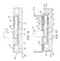
- FIG. 2 is a perspective view of an upright wall panel showing a cover tile partially attached to one side thereof.
- FIG. 3 illustrates the back side of a cover tile prior to mounting of connector brackets thereon.
- FIG. 4 is a cross-sectional view through the cover tile as taken generally along line 4 - 4 in FIG. 3 .
- FIG. 5 is an enlarged fragmentary view showing only one corner of the cover tile illustrated in FIG. 3 .
- FIG. 6 illustrates the back side of the cover tile similar to FIG. 3 but with the connector brackets mounted thereon adjacent the four corners of the cover tile.
- FIG. 6A is an enlarged view corresponding to FIG. 6 but showing only the corners with the brackets attached.
- FIGS. 7 and 8 are side and top views, respectively, of the cover tile shown in FIG. 6 .
- FIG. 9 is a perspective view of the corner bracket which cooperates with an upper corner of the cover tile, namely the upper left corner in FIG. 6 .
- FIG. 10 is a front view of the corner bracket shown in FIG. 9 .
- FIG. 11 is a left side elevational view of the corner bracket shown in FIG. 10 .
- FIG. 12 is a top view of the corner bracket shown in FIG. 10 .
- FIG. 13 is a perspective view of the corner bracket associated with a lower corner of the cover tile, specifically the lower left corner of the cover tile illustrated in FIG. 6 .
- FIG. 14 is a front view of the corner bracket illustrated in FIG. 13 .
- FIG. 15 is a left side elevational view of the corner bracket illustrated in FIG. 14 .
- FIG. 16 is a top view of the corner bracket illustrated in FIG. 14 .
- FIG. 17 is a fragmentary, enlarged sectional view taken generally along line 17 - 17 in FIG. 6 and illustrating the top bracket as attached to the cover tile edge rail.
- FIG. 18 is a view similar to FIG. 17 but sectioned generally through the locking tab.
- FIG. 19 is a fragmentary, enlarged sectional view taken generally along line 19 - 19 in FIG. 6 and illustrating the bottom bracket as attached to the cover tile edge rail.
- FIG. 20 is a view similar to FIG. 19 but sectioned generally through the locking tab.
- FIG. 21 is an enlarged perspective view showing solely the rear left upper corner of the cover tile.
- the wall system 10 is formed by a plurality of prefabricated upright wall panels 11 which, in a conventional manner, can be serially connected in aligned and/or transverse relationship to divide a large open space into smaller work spaces.
- the upright wall panel 11 includes an inner upright rigid frame 12 which, in the illustrated embodiment, is formed principally as a ring-shaped rectangular structure having generally parallel top and bottom elongate frame members or rails 13 and 14 , respectively, which extend generally horizontally.
- the frame 12 also includes a pair of generally parallel vertical or upright edge frame members or rails 15 and 16 which extend between and are rigidly joined, such as by welding, to adjacent ends of the top and bottom frame members 13 - 14 .
- the upright frame members 15 - 16 in the illustrated arrangement, have lower leg parts 17 which not only mount thereon floor-engaging support glides, but which are also of reduced width to cooperate with an internal chamber formed along the bottom of the wall panel for accommodating power and/or communication cabling, such being a conventional and well known feature in upright wall panels of this general type.
- the lower leg parts 17 in the illustrated arrangement, are rigidly joined by a bottom pan or member 18 which extends horizontally therebetween and which extends in parallel relationship to the horizontal frame members 13 - 14 .
- the panel frame 12 is also frequently provided with one or more crossbeams 19 extending at various elevations within the frame and projecting horizontally between the edge uprights 15 - 16 , with the crossbeams 19 being either rigidly or releasably joined to the upright frame members 15 - 16 .
- the frame members which make up the frame are preferably formed by elongate hollow members, such as tubular metal members having a square or rectangular cross-section.
- the wall panel 11 is preferably provided on one, and typically both, sides thereof with one or more detachable cover tiles or pads 21 . While a single large cover tile can be used to cover an entire side of the wall panel frame, it is typical and conventional to provide two or more such cover tiles on each side of the panel frame, with the cover tiles being disposed vertically one above the other to provide increased flexibility with respect to use and aesthetics.
- the cover tile 21 is adapted for releasable engagement on the wall panel frame, and for this purpose, the frame is typically provided with openings in the frame members, such as openings 22 formed through the side walls of the upright frame members 15 - 16 , and/or openings 23 formed through the side walls in the horizontal frame members 13 - 14 .
- the cooperation of the cover tiles 21 with the frame 12 will be explained in greater detail hereinafter.
- the cover tile 21 in accordance with the present invention includes a main plate-like pad or substrate 31 which is generally rectangular and has height and width dimensions which are relatively large in comparison to the thickness dimension of the pad.
- the pad 31 in a preferred embodiment is formed of a compressed fiberglass to create a relatively stiff but thin mat, although it will be appreciated that numerous other conventional materials such as fiber board, hard board, wood or other suitable materials may be used for defining the substrate 31 .
- the substrate or pad 31 has, on the back or inner side face 32 thereof, a reinforcing frame 33 positioned in overlying adjacent relationship, which frame 33 is fixedly related to the pad 31 when the cover tile 21 is fully assembled.
- the frame 33 is formed generally as a rectangular ring-shaped structure defined by generally horizontally elongated top and bottom frame elements 34 and 35 respectively, the latter being rigidly joined to generally parallel right and left edge frame elements 36 and 37 respectively which perpendicularly extend between the ends of the horizontal frame elements.
- the frame 33 is disposed so that the individual frame elements or rails are positioned adjacent and extend lengthwise along the respective outer edges of the substrate 31 , and the frame elements adjacent the corner of the frame are rigidly joined together in any conventional manner which, in the illustrated embodiment, involves the use of deformations such as dimples or mushroom-type deformed beads 53 which are provided at each corner of the frame.
- each frame rail 34 - 37 are all preferably of substantially identical cross-section and, as illustrated by FIGS. 4 and 17 , each frame rail includes a generally planar base wall 41 which extends lengthwise of the frame rail and is positioned in closely adjacent and substantially overlying relationship to the rear face of the pad 31 .
- the base wall 41 adjacent the outer edge thereof has a U- or channel-shaped edge part 42 extending lengthwise therealong for defining the outer extremity of the rail and of the cover tile.
- This edge part 42 protrudes inwardly away from the base wall 41 , and defines thereon an outer leg 43 which projects forwardly and overlaps the outer edge 44 of the pad 31 .
- Each frame rail also has an inner edge part 45 associated with and extending lengthwise along the inner edge of the base wall 41 .
- This inner edge part 45 is generally L-shaped in cross-section and includes a first leg or flange 46 which projects transversely inwardly (i.e. rearwardly) from the base wall 41 , with the flange 46 joining to a second flange or leg 47 which protrudes transversely from the flange 46 so as to be disposed in generally parallel but rearwardly spaced relationship from the base wall 41 .
- This rearward flange 47 projects outwardly toward the peripheral edge of the pad 31 and terminating at a free edge 48 .
- This inner L-shaped edge part 45 and its cooperation with the base wall 41 causes the inner edge of the frame rail to have a generally U-shaped configuration which opens in a direction toward the adjacent free edge of the pad.
- This inner edge part 45 in the lengthwise direction of the rail, terminates at an end edge 49 which is spaced inwardly from the corresponding end edge of the outer edge part 42 so as to permit the horizontal and vertical frame rails, where they meet at the corner, to define a substantially continuous ring-shaped configuration.
- the cover tile 21 including the pad 31 and the reinforcing frame 33 associated with the back side thereof, is additionally provided with a flexible covering sheet (not shown), such as a cloth, fabric, foil, plastic, vinyl or equivalent, which overlies and is adhesively secured to the front face of the pad 31 , with the projecting peripheral edges of the cover sheet being wrapped around the outer edge portions of the frame rails and adhesively secured thereto so as to fixedly join the frame 33 and pad 31 together.
- a flexible covering sheet such as a cloth, fabric, foil, plastic, vinyl or equivalent
- the rear side of the cover tile 21 is provided, adjacent each corner, with a connector bracket which attaches to the frame 33 and creates a releasable engagement with the panel frame 12 .
- the left and right upper corners of the cover tile are respectively provided with connector brackets 61 and 61 ′
- the left and right lower corners of the cover tile are respectively provided with connector brackets 101 and 101 ′.
- the brackets 61 and 61 ′ are identical except for being mirror images of one another, and similarly the lower corner brackets 101 and 101 ′ are also identical except for being mirror images of one another. The construction of the brackets is described below.
- the connector bracket 61 (or 61 ′), as illustrated by FIGS. 9-12 , includes a main U- or channel-shaped open body 62 defined by respective outer and inner plate-like walls or legs 63 and 64 , the latter being cantilevered in generally parallel relationship from an edge or bridge wall 65 which extends transversely, and more specifically perpendicularly, therebetween.
- the construction defined by the walls 63 and 64 , and their joinder by the bridge wall 65 results in the main body 62 having a generally open interior 70 as defined between the parallel walls 63 - 64 , which open interior has a height which generally corresponds to the height associated with the inner edge part 45 formed on each of the frame rails 34 - 37 .
- the flat outer side wall 63 of the bracket main body 62 is defined generally between two parallel side edges 66 which project transversely from the bridge wall 65 , with the outer side wall 63 extending a substantial distance outwardly away from the bridge wall 65 so as to terminate at a remote edge 67 .
- the outer side wall 63 has a generally U-shaped opening 68 formed transversely therethrough at a generally central location, that is, in spaced relationship from all of the side edges of the side wall 63 .
- This U-shaped opening 68 surrounds and results in defining a positioning tab 69 which is joined to the outer side wall 63 generally at a bend line 71 , with the tab 69 being cantilevered away from this bend line so as to terminate at a free edge 72 .
- the cantilevered direction of this tab 69 i.e. the direction extending from the bend line 71 to the free edge 72 , occurs generally toward the bridge wall 65 .
- This positioning tab 69 is physically deformed and more specifically bent inwardly about the bend line 71 so that the free edge 72 of the tab is displaced inwardly a small extent relative to the inner back surface 73 of the outer side wall 63 , as illustrated in FIG. 12 .
- This small sideward displacement of the free edge 72 of tab 69 enables the connector bracket 61 to be secured to the respective edge frame member 34 - 37 , as explained hereinafter.
- the outer side wall 63 also has at least one, and in the illustrated embodiment two, locking tabs 74 associated therewith. These locking tabs 74 are positioned adjacent opposite side edges 66 of the outer side wall, and have a generally triangular configuration defined on one side by the side edge 66 and on another side by a cutting line 75 which extends transversely through the side wall and projects transversely inwardly a short distance from the side edge 66 .
- the locking tab 74 on its third side is defined by a short bend line 76 which extends angularly between the inner end of the cut 75 and the adjacent outer side edge 66 , with the locking tab 74 being deformed or slightly bent inwardly about the bend line 76 so that the tab protrudes inwardly beyond the inner back surface 73 of the side wall 63 .
- the locking tab 74 hence protrudes inwardly in the same direction as the positioning tab 69 .
- the pair of sidewardly-spaced locking tabs 74 are positioned generally on opposite sides of the positioning tab 69 , with the cutting lines 75 being aligned and spaced from the edge wall 65 by a slightly greater distance than the spacing between the edge wall 65 and the free edge 72 of the positioning tab.
- the bracket 61 also has a projection 78 , specifically a spring clip, which is carried on the outer side wall 63 and projects transversely outwardly from the plane of the side wall at a location closely adjacent the remote edge 67 thereof.
- the clip or projection 78 includes a base leg 79 which protrudes generally perpendicularly outwardly away from the side wall 63 , being joined thereto through a generally right-angle bend 81 .
- the base leg 79 is cantilevered outwardly and adjacent its outer extremity joins to a nose part 82 of the projection, which nose part 82 is defined by a reverse bend which in turn joins to an upper spring leg 83 which is cantilevered inwardly back toward the outer side wall 63 .
- This spring leg 83 is defined with an arcuate or angled cross-sectional configuration defined by an outer leg part 84 which joins to the nose bend 82 and projects inwardly while being somewhat angled upwardly.
- the outer leg part 84 then joins through an intermediate bend 85 to an inner leg part 86 which project inwardly and downwardly and terminates at an inner free edge 87 , the latter being disposed in close proximity to the plane of the outer side wall 63 .
- the upper spring leg 83 is normally spaced from the base leg 79 and hence can be resiliently deflected downwardly at least a limited extent in a direction toward the base leg 79 when the spring clip 78 is moved into engagement with an opening 22 formed in the wall panel frame.
- the height of the spring clip 78 when in a resiliently non-deflected condition, as illustrated in FIG. 11 , is slightly greater than the height of the opening 22 formed in the panel frame so as to ensure that the upper spring leg 83 resiliently deflects when the clip 78 is inserted into the opening 22 , and then expands after passing over the top bend 85 so that the clip provides a barb-like function so as to effect retention of the cover tile to the panel frame.
- the outer side wall 63 of connector bracket 61 also has a stop or position limiting flange 89 associated with the remote edge 67 of the outer side wall, which flange 89 is cantilevered generally perpendicularly inwardly from the outer side wall 63 in a direction towards the inner side wall 65 .
- This cantilevered stop flange 89 is cantilevered inwardly through only a short transverse distance so that the free edge thereof is normally positioned in close proximity to the base wall 41 of the frame rail when the connector bracket is mounted thereon.
- this bracket also includes a main U- or channel-shaped open body 102 having sidewardly spaced but generally parallel plate-like outer and inner side walls 103 and 104 , respectively, which are transversely joined by a bridge or edge wall 105 , whereby the main body 102 defines an opening or recess 110 between the side walls which generally corresponds to the height of the rail edge part 45 .
- the outer side wall 103 has side edges 106 which project outwardly away from the bridge wall 105 , with the cantilevered side wall 103 terminating at a remote edge 107 .
- the outer side wall 103 has a U- or channel-shaped opening 108 extending transversely therethrough at a location spaced inwardly from the edges of the side wall, and this opening 108 surrounds and defines a cantilevered positioning tab 109 which is joined to the side wall 103 at one end by means of a bend line 111 , with the cantilevered positioning tab 109 projecting inwardly toward the bridge wall 105 and terminating at a free edge 112 .
- This positioning tab 109 is bent or deformed inwardly from the plane of the side wall 103 in a direction generally toward the other side 104 , whereby the free edge 112 is positioned adjacent and projects slightly inwardly relative to the inner side surface 113 of the side wall 103 .
- the outer side wall 103 of bracket 101 also has a pair of sidewardly spaced locking tabs 114 formed therein directly adjacent the opposite side edges 106 thereof, each said locking tab 114 being defined by a cutting line 115 which extends a small distance transversely inwardly from the respective side edge 106 , and by a bend line 116 which extends in angled relationship between the inner end of the cut line 115 and the adjacent side edge 106 .
- Each tab 114 is bent inwardly a small amount about the bend line 116 so that the tab projects inwardly beyond the inner side surface 113 .
- outer side wall 103 substantially corresponds to the equivalent structure associated with the outer side wall associated with the top bracket 61 , whereby further detailed description thereof is believed unnecessary.
- the corner bracket 101 adjacent the remote edge 107 of the outer side wall 103 , also has a projection 117 , specifically a clip part, cantilevered transversely outwardly therefrom for cooperation with an opening 22 associated with the panel frame.
- the projection 117 as associated with the lower corner bracket 101 is somewhat differently configured in comparison to the upper corner bracket 61 in that the clip part 117 is shaped to function as a hook, rather than as a spring clip.
- the clip part 117 includes a plate-like bridge part 118 which is bent from the side wall 103 and projects generally perpendicularly outwardly away from the remote edge 107 through a small extent.
- This bridge part 118 in turn joins to a flat engaging part 120 , formed generally as a finger-like hook, which is formed as an elongate cantilever which projects outwardly and downwardly.
- This finger-like hook 120 is defined by vertically spaced top and bottom edges 121 and 122 , respectively, which both slope downwardly as they project outwardly, with these edges terminating at a rounded lower free end 123 , the latter defining the nose of the hook part 120 .
- the lower edge 121 of the hook part where it transitions to the bridge part 118 , has a small slot 123 opening upwardly through a small extent, which slot is sized to accommodate the wall thickness of the panel frame as defined adjacent the hook-accommodating opening 22 formed therein.
- the plane of the hook part 120 extends at a small angle relative to the perpendicular relationship defined by the bridge part 118 as it extends perpendicularly from the plane of the side wall 103 .
- This angle designated 125 in FIG. 16 , is normally in the range of 10 degrees to 20 degrees, preferably about 15 degrees.
- the other or inner side wall 104 of the bracket 101 is preferably formed as a generally flat and planar plate which is free of tabs, and which terminates in a free edge 126 which is spaced significantly inwardly in closer proximity to the bridge or edge wall 105 than the remote edge of the outer side wall 103 .
- each bracket is preferably formed as a monolithic one-piece member by being formed from thin metal plate, preferably thin steel sheet, with the member being initially cut or stamped from a flat plate to create a suitable blank, which blank is then suitably shaped so as to result in the configuration of the bracket 61 or 101 as described above and as illustrated herein.
- the cover tile 21 has been assembled by initially forming the reinforcing frame 33 , positioning the frame 33 adjacent the back side of the pad 31 , and then wrapping the fabric covering as adhered to the front face of the pad around the pad edges and around the edges of the frame rails so as to adhesively secure the fabric to the frame rails and hence create a unitary construction for the cover tile, then the connector brackets are attached to the four corners of the frame 33 . This attachment of the corner brackets to the cover tile may occur in the factory, or may ultimately be carried out at the job site.
- the bracket To mount the connector bracket 61 to the rear upper left corner of the cover tile, the bracket is positioned inwardly of the upper corner, and is then slidably displaced horizontally outwardly so that the channel-shaped body 62 of the bracket slidably telescopes over and around the inner edge part 45 of the left edge frame element 37 .
- the plate-like outer side wall 63 resiliently deflects to allow passage of the tabs 69 and 74 over the flange 47 .
- the locking tabs 74 snap downwardly so as to overlap the free edge 48 of the flange 47 , thereby restricting reverse or withdrawal movement of the bracket.
- the positioning tab 69 also snaps downwardly into the positioning notch 51 (assuming that it is properly aligned therewith), or if misaligned then the bracket is forcibly moved lengthwise along the frame rail until the positioning tab 69 aligns with and moves transversely into the positioning notch 51 .
- the spring clip) 78 protrudes rearwardly at a desired location for cooperation with an upright rail 15 , 16 of the panel frame.
- the edge flange 91 is positioned so that it protrudes downwardly into close proximity with the base wall 41 of the edge rail so as to prevent any significant inward resilient deflection of the plate-like outer side wall 63 .
- the lower left corner bracket 101 is mounted onto the lower end of the left side edge rail 37 following the same technique as described above relative to the upper corner bracket 61 .
- the tile can then be mounted on an appropriate sized panel frame by initially positioning the tile adjacent the panel frame so that the protruding lower hooks 120 as provided adjacent the opposite lower corners can be aligned with and partially inserted into the frame openings 22 .
- the angularity of the hooks and the converging relationship between the pair of hooks as they extend toward the back side of the cover tile effectively causes a sideward centering of the cover tile so as to effectively result in the hooks, when fully seated within the openings, to substantially bear against the inner edge of the respective opening.
- the cover tile 21 is manually swung inwardly toward the wall panel frame, causing the spring clips 78 on the upper brackets to enter into their respective frame openings 22 . Since the vertical dimension of the spring clips 78 slightly exceeds the vertical dimension of the frame openings 22 , the spring clips 78 undergo a limited resilient deflection as they are manually forced through the openings. Due to the curved or angular shape of the top leg of the spring clips 78 , the passage of the projections through the openings causes the spring clips to resiliently expand to hence create an engagement which retains the upper spring clips within the openings and hence retains the cover tile in snug engagement with the face of the panel frame.
Landscapes
- Engineering & Computer Science (AREA)
- Architecture (AREA)
- Physics & Mathematics (AREA)
- Electromagnetism (AREA)
- Civil Engineering (AREA)
- Structural Engineering (AREA)
- Finishing Walls (AREA)
Abstract
Description
Claims (16)
Priority Applications (1)
| Application Number | Priority Date | Filing Date | Title |
|---|---|---|---|
| US11/982,878 US7856777B2 (en) | 2006-11-06 | 2007-11-06 | Clip arrangement for wall panel tiles |
Applications Claiming Priority (2)
| Application Number | Priority Date | Filing Date | Title |
|---|---|---|---|
| US85709406P | 2006-11-06 | 2006-11-06 | |
| US11/982,878 US7856777B2 (en) | 2006-11-06 | 2007-11-06 | Clip arrangement for wall panel tiles |
Publications (2)
| Publication Number | Publication Date |
|---|---|
| US20080104926A1 US20080104926A1 (en) | 2008-05-08 |
| US7856777B2 true US7856777B2 (en) | 2010-12-28 |
Family
ID=39358505
Family Applications (1)
| Application Number | Title | Priority Date | Filing Date |
|---|---|---|---|
| US11/982,878 Active 2028-02-01 US7856777B2 (en) | 2006-11-06 | 2007-11-06 | Clip arrangement for wall panel tiles |
Country Status (1)
| Country | Link |
|---|---|
| US (1) | US7856777B2 (en) |
Cited By (13)
| Publication number | Priority date | Publication date | Assignee | Title |
|---|---|---|---|---|
| US8966842B2 (en) | 2012-09-17 | 2015-03-03 | Steelcase Inc. | Floor-to-ceiling partition wall assembly |
| US8967054B2 (en) | 2011-06-03 | 2015-03-03 | Kimball International, Inc. | Office desking system |
| USD753943S1 (en) | 2011-06-11 | 2016-04-19 | Dirtt Environmental Solutions, Ltd | Modular wall nesting system |
| USD754991S1 (en) | 2011-12-28 | 2016-05-03 | Dirtt Environmental Solutions, Ltd | Modular wall incorporating recessed, extendable furniture |
| US9943165B2 (en) | 2016-02-10 | 2018-04-17 | Dirtt Environmental Solutions, Ltd. | Embedded furniture having retractible legs with lighting |
| USRE46929E1 (en) | 2004-08-17 | 2018-07-03 | Dirtt Environmental Solutions, Ltd | Integrated reconfigurable wall system |
| US10329759B2 (en) | 2012-09-17 | 2019-06-25 | Steelcase Inc. | Floor-to-ceiling partition wall assembly |
| CN111005479A (en) * | 2019-12-06 | 2020-04-14 | 上海模卡建筑工程科技发展有限公司 | Prefabricated wall body of assembled |
| US11085184B2 (en) | 2014-02-20 | 2021-08-10 | Dirtt Environmental Solutions Ltd. | Interface for mounting interchangable components |
| US11093087B2 (en) | 2016-06-10 | 2021-08-17 | Dirtt Environmental Solutions Ltd. | Glass substrates with touchscreen technology |
| USRE48722E1 (en) | 2004-08-17 | 2021-09-07 | Dirtt Environmental Solutions Ltd. | Integrated reconfigurable wall system |
| US11240922B2 (en) | 2016-06-10 | 2022-02-01 | Dirtt Environmental Solutions Ltd. | Wall system with electronic device mounting assembly |
| US11550178B2 (en) | 2016-07-08 | 2023-01-10 | Dirtt Environmental Solutions Inc. | Low-voltage smart glass |
Families Citing this family (4)
| Publication number | Priority date | Publication date | Assignee | Title |
|---|---|---|---|---|
| ITPR20090025A1 (en) * | 2009-04-15 | 2010-10-16 | Coopsette Societa Cooperativa | MULTI-FUNCTION PARIETAL STRUCTURE |
| EP2434068A3 (en) * | 2010-09-24 | 2013-01-23 | Principle Holdings Limited | Modular walling system |
| DE202013100161U1 (en) * | 2013-01-11 | 2013-02-25 | Knauf Gips Kg | Drywall ceiling / -wall |
| US11608634B2 (en) * | 2019-05-03 | 2023-03-21 | Watson Furniture Group, Inc. | Flexible workspace partition system |
Citations (12)
| Publication number | Priority date | Publication date | Assignee | Title |
|---|---|---|---|---|
| US4423573A (en) | 1978-11-08 | 1984-01-03 | American Seating Company | Wall panel with removable acoustical insert |
| US4575983A (en) * | 1985-02-01 | 1986-03-18 | Nucor Corporation | Sliding hold-down clip for standing seam metal roof |
| US4685255A (en) | 1984-09-10 | 1987-08-11 | Herman Miller, Inc. | Work space management system |
| US4704835A (en) * | 1985-09-30 | 1987-11-10 | Lamar Jordan | Hook strip for removable wall panels |
| US4905428A (en) * | 1988-11-16 | 1990-03-06 | Sykes Christopher C | Partition structures and frame elements therefor |
| US5802789A (en) | 1996-12-17 | 1998-09-08 | Steelcase, Inc. | Partition construction including removable cover panels |
| US5816001A (en) | 1996-07-26 | 1998-10-06 | Steelcase Inc. | Partition construction including interconnection system and removable covers |
| US5943834A (en) | 1996-12-17 | 1999-08-31 | Steelcase Inc. | Partition construction |
| US6115977A (en) | 1998-09-11 | 2000-09-12 | Krueger International, Inc. | Knock-down panel partition system |
| US6684929B2 (en) * | 2002-02-15 | 2004-02-03 | Steelcase Development Corporation | Panel system |
| US6775953B2 (en) | 2002-05-31 | 2004-08-17 | Hon Technology Inc. | Simplified wall panel |
| US6941716B2 (en) | 2002-10-02 | 2005-09-13 | Hni Technologies Inc. | Universal wall panel tile connector |
-
2007
- 2007-11-06 US US11/982,878 patent/US7856777B2/en active Active
Patent Citations (19)
| Publication number | Priority date | Publication date | Assignee | Title |
|---|---|---|---|---|
| US4423573A (en) | 1978-11-08 | 1984-01-03 | American Seating Company | Wall panel with removable acoustical insert |
| US4685255A (en) | 1984-09-10 | 1987-08-11 | Herman Miller, Inc. | Work space management system |
| US4575983A (en) * | 1985-02-01 | 1986-03-18 | Nucor Corporation | Sliding hold-down clip for standing seam metal roof |
| US4704835A (en) * | 1985-09-30 | 1987-11-10 | Lamar Jordan | Hook strip for removable wall panels |
| US4905428A (en) * | 1988-11-16 | 1990-03-06 | Sykes Christopher C | Partition structures and frame elements therefor |
| US6009676A (en) | 1996-07-26 | 2000-01-04 | Steelcase Developement Inc. | Connector for partition system |
| US6173545B1 (en) | 1996-07-26 | 2001-01-16 | Steelcase Development Inc. | Connector for partition system |
| US5816001A (en) | 1996-07-26 | 1998-10-06 | Steelcase Inc. | Partition construction including interconnection system and removable covers |
| US5816001B1 (en) | 1996-07-26 | 2000-06-06 | Steelcase Inc | Partition construction including interconnection system and removable covers |
| US6000180A (en) | 1996-12-17 | 1999-12-14 | Steelcase Inc. | Partition system with removable cover panels |
| US5943834A (en) | 1996-12-17 | 1999-08-31 | Steelcase Inc. | Partition construction |
| US5802789B1 (en) | 1996-12-17 | 2000-11-07 | Steelcase Inc | Partition construction including removable cover panels |
| US5802789A (en) | 1996-12-17 | 1998-09-08 | Steelcase, Inc. | Partition construction including removable cover panels |
| US6115977A (en) | 1998-09-11 | 2000-09-12 | Krueger International, Inc. | Knock-down panel partition system |
| US6131347A (en) | 1998-09-11 | 2000-10-17 | Krueger International, Inc. | Reconfigurable wall panel partition system |
| US6397533B1 (en) | 1998-09-11 | 2002-06-04 | Krueger International, Inc. | Tile and mounting arrangement for a wall panel system |
| US6684929B2 (en) * | 2002-02-15 | 2004-02-03 | Steelcase Development Corporation | Panel system |
| US6775953B2 (en) | 2002-05-31 | 2004-08-17 | Hon Technology Inc. | Simplified wall panel |
| US6941716B2 (en) | 2002-10-02 | 2005-09-13 | Hni Technologies Inc. | Universal wall panel tile connector |
Cited By (19)
| Publication number | Priority date | Publication date | Assignee | Title |
|---|---|---|---|---|
| USRE47132E1 (en) | 2004-08-17 | 2018-11-20 | Dirtt Environmental Solutions, Ltd | Integrated reconfigurable wall system |
| USRE48722E1 (en) | 2004-08-17 | 2021-09-07 | Dirtt Environmental Solutions Ltd. | Integrated reconfigurable wall system |
| USRE46929E1 (en) | 2004-08-17 | 2018-07-03 | Dirtt Environmental Solutions, Ltd | Integrated reconfigurable wall system |
| USRE47693E1 (en) | 2004-08-17 | 2019-11-05 | Dirtt Environmental Solutions, Ltd. | Integrated reconfigurable wall system |
| US8967054B2 (en) | 2011-06-03 | 2015-03-03 | Kimball International, Inc. | Office desking system |
| USD753943S1 (en) | 2011-06-11 | 2016-04-19 | Dirtt Environmental Solutions, Ltd | Modular wall nesting system |
| US9347218B2 (en) | 2011-06-11 | 2016-05-24 | Dirtt Environmental Solutions, Ltd. | Modular wall nesting system |
| USD754991S1 (en) | 2011-12-28 | 2016-05-03 | Dirtt Environmental Solutions, Ltd | Modular wall incorporating recessed, extendable furniture |
| US10920418B2 (en) | 2011-12-28 | 2021-02-16 | Dirtt Environmental Solutions, Ltd | Modular walls incorporating recessed, extendable furniture |
| US9487949B2 (en) | 2012-09-17 | 2016-11-08 | Steelcase Inc. | Method of positioning and installing a panel member on a floor-to-ceiling partition wall frame assembly |
| US8966842B2 (en) | 2012-09-17 | 2015-03-03 | Steelcase Inc. | Floor-to-ceiling partition wall assembly |
| US10329759B2 (en) | 2012-09-17 | 2019-06-25 | Steelcase Inc. | Floor-to-ceiling partition wall assembly |
| US11085184B2 (en) | 2014-02-20 | 2021-08-10 | Dirtt Environmental Solutions Ltd. | Interface for mounting interchangable components |
| US10058170B2 (en) | 2016-02-10 | 2018-08-28 | Dirtt Environmental Solutions, Ltd | Modular walls with embedded furniture and opposing feature |
| US9943165B2 (en) | 2016-02-10 | 2018-04-17 | Dirtt Environmental Solutions, Ltd. | Embedded furniture having retractible legs with lighting |
| US11093087B2 (en) | 2016-06-10 | 2021-08-17 | Dirtt Environmental Solutions Ltd. | Glass substrates with touchscreen technology |
| US11240922B2 (en) | 2016-06-10 | 2022-02-01 | Dirtt Environmental Solutions Ltd. | Wall system with electronic device mounting assembly |
| US11550178B2 (en) | 2016-07-08 | 2023-01-10 | Dirtt Environmental Solutions Inc. | Low-voltage smart glass |
| CN111005479A (en) * | 2019-12-06 | 2020-04-14 | 上海模卡建筑工程科技发展有限公司 | Prefabricated wall body of assembled |
Also Published As
| Publication number | Publication date |
|---|---|
| US20080104926A1 (en) | 2008-05-08 |
Similar Documents
| Publication | Publication Date | Title |
|---|---|---|
| US7856777B2 (en) | Clip arrangement for wall panel tiles | |
| US5899036A (en) | Partition system | |
| CN1932197B (en) | Molding for suspended panel ceiling | |
| JP2005517841A (en) | Panel system | |
| MX2008001087A (en) | Wall mold attachment clip. | |
| JPH0515857B2 (en) | ||
| JPH04228749A (en) | Office space dividing system | |
| US20100186326A1 (en) | Panel tile and top cap retention system | |
| KR102945931B1 (en) | Fastening system and window covering including the fastening system | |
| US7707795B2 (en) | Wall panel with gusseted open frame | |
| US4907773A (en) | Adjustable mounting surface | |
| JPH0996173A (en) | Window connecting frame | |
| US20110308185A1 (en) | Suspended ceiling system for "T" bar grid system | |
| KR200384824Y1 (en) | Bracket for fixing panel and construction structure of panel-wall using the same | |
| JP2018071327A (en) | Partition device | |
| KR102818320B1 (en) | Fixing clips for ceiling finishing with different heights, ceiling structure for indirect lighting installation using the same, and its construction method | |
| JP3485051B2 (en) | Panel board structure of partition panel | |
| JPH0544294A (en) | Ceiling frame | |
| JP5862124B2 (en) | Partition panel | |
| JP4325513B2 (en) | Low partition panel connection structure and connection stud | |
| JPH0516918U (en) | Baseboard connection device | |
| JP2560813Y2 (en) | Mounting bracket for square members in houses, etc. | |
| CN210095306U (en) | Picture frame fixing structure | |
| JP2774406B2 (en) | Wall mounting fixture and wall mounting structure | |
| JPH11324354A (en) | Connecting structure of wall member of unit room |
Legal Events
| Date | Code | Title | Description |
|---|---|---|---|
| AS | Assignment |
Owner name: HAWORTH, INC., MICHIGAN Free format text: ASSIGNMENT OF ASSIGNORS INTEREST;ASSIGNORS:LAMFERS, ALEX;KONING, DAVID;REEL/FRAME:021643/0338 Effective date: 20071105 |
|
| STCF | Information on status: patent grant |
Free format text: PATENTED CASE |
|
| CC | Certificate of correction | ||
| FEPP | Fee payment procedure |
Free format text: PAYOR NUMBER ASSIGNED (ORIGINAL EVENT CODE: ASPN); ENTITY STATUS OF PATENT OWNER: LARGE ENTITY |
|
| AS | Assignment |
Owner name: PNC BANK, NATIONAL ASSOCIATION, AS ADMINISTRATIVE Free format text: COLLATERAL ASSIGNMENT OF PATENTS;ASSIGNOR:HAWORTH, INC., HAWORTH, LTD. AND SUCCESSORS;REEL/FRAME:032606/0875 Effective date: 20140403 |
|
| FPAY | Fee payment |
Year of fee payment: 4 |
|
| MAFP | Maintenance fee payment |
Free format text: PAYMENT OF MAINTENANCE FEE, 8TH YEAR, LARGE ENTITY (ORIGINAL EVENT CODE: M1552) Year of fee payment: 8 |
|
| AS | Assignment |
Owner name: HAWORTH, INC., MICHIGAN Free format text: RELEASE BY SECURED PARTY;ASSIGNOR:PNC BANK, NATIONAL ASSOCIATION;REEL/FRAME:052788/0497 Effective date: 20200528 Owner name: HAWORTH, LTD., MICHIGAN Free format text: RELEASE BY SECURED PARTY;ASSIGNOR:PNC BANK, NATIONAL ASSOCIATION;REEL/FRAME:052788/0497 Effective date: 20200528 |
|
| MAFP | Maintenance fee payment |
Free format text: PAYMENT OF MAINTENANCE FEE, 12TH YEAR, LARGE ENTITY (ORIGINAL EVENT CODE: M1553); ENTITY STATUS OF PATENT OWNER: LARGE ENTITY Year of fee payment: 12 |
|
| AS | Assignment |
Owner name: PNC BANK, PENNSYLVANIA Free format text: COLLATERAL ASSIGNMENT OF PATENTS;ASSIGNORS:HAWORTH, INC.;AFFORDABLE INTERIOR SYSTEMS, INC.;REEL/FRAME:062078/0770 Effective date: 20221129 |
|
| AS | Assignment |
Owner name: PNC BANK, NATIONAL ASSOCIATION, PENNSYLVANIA Free format text: SECURITY INTEREST;ASSIGNOR:HAWORTH, INC.;REEL/FRAME:074279/0827 Effective date: 20260107 |