US7854411B2 - Aircraft undercarriage including a plurality of electromechanical actuators, and a method of testing it - Google Patents
Aircraft undercarriage including a plurality of electromechanical actuators, and a method of testing it Download PDFInfo
- Publication number
- US7854411B2 US7854411B2 US11/507,463 US50746306A US7854411B2 US 7854411 B2 US7854411 B2 US 7854411B2 US 50746306 A US50746306 A US 50746306A US 7854411 B2 US7854411 B2 US 7854411B2
- Authority
- US
- United States
- Prior art keywords
- bottom portion
- undercarriage
- actuator
- actuators
- steering
- Prior art date
- Legal status (The legal status is an assumption and is not a legal conclusion. Google has not performed a legal analysis and makes no representation as to the accuracy of the status listed.)
- Active, expires
Links
Images


Classifications
-
- B—PERFORMING OPERATIONS; TRANSPORTING
- B64—AIRCRAFT; AVIATION; COSMONAUTICS
- B64C—AEROPLANES; HELICOPTERS
- B64C25/00—Alighting gear
- B64C25/32—Alighting gear characterised by elements which contact the ground or similar surface
- B64C25/50—Steerable undercarriages; Shimmy-damping
Definitions
- the invention relates to an aircraft undercarriage including a plurality of electromechanical steering actuators.
- Aircraft undercarriages are known that include a bottom portion that is steerable and a steering member adapted to turn the steerable bottom portion in response to a steering order.
- the steering member often includes one or more actuators which act on the steerable bottom portion.
- Other types of steering member are known, e.g. using a rack.
- steering members that include an actuator with a hydraulic motor co-operating with a toothed ring secured to the steerable bottom portion of the undercarriage.
- a steering member including an actuator with an electric motor co-operating with a toothed ring secured to the steerable bottom portion of the undercarriage.
- the invention seeks to improve steering control and to provide new possibilities for use.
- the invention provides an aircraft undercarriage including a steerable bottom portion and a steering member suitable for turning the steerable bottom portion in response to a steering order
- the steering member comprises a plurality of electro-mechanical steering actuators each comprising at least one main electric motor, and the actuators are disposed on the undercarriage so as to enable all of them to co-operate simultaneously with the steerable bottom portion in order to steer it, each of the electromechanical steering actuators including controllable coupling means for selectively placing the actuator:
- the aircraft can then be allowed to take off from an airport even if a spare actuator is not available at that airport, thus contributing to making the aircraft easier to operate.
- FIG. 1 is a diagrammatic view of the bottom of an undercarriage fitted with electromechanical steering actuators of the invention
- FIG. 2 is a plan view of the FIG. 1 undercarriage
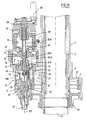
- FIG. 3 is a section view through an electro-mechanical steering actuator on line III-III of FIG. 2 , the shock absorber being removed, the coupling member being shown in its coupled position;
- FIG. 4 is a fragmentary section view on line IV-IV of FIG. 3 ;
- FIG. 5 is a section view on line V-V of FIG. 3 showing a portion of the coupling member in the coupled state
- FIG. 6 is a section view on line VI-VI of FIG. 7 ;
- FIG. 7 is a section view analogous to that of FIG. 3 showing the coupling member in the uncoupled state.
- FIG. 8 is a section view analogous to FIG. 3 showing a variant embodiment.
- the under-carriage shown comprises a main fitting 1 , also called cylinder, in which a turnable tube 2 is mounted to turn about a longitudinal axis Z 1 .
- a telescopic shock absorber 3 extends inside the turnable tube 2 .
- the bottom portion of the shock absorber projects from the tube 2 and carries an axle 4 that receives wheels 5 .
- a scissors linkage 6 extends between the tube 2 and the shock absorber 3 to constrain the tube 2 to turn with the shock absorber 3 while allowing the shock absorber to shorten freely into the main fitting 1 along the axis Z 1 .
- the tube 2 carries a toothed ring 7 (shown in FIG. 3 ) which is received in a housing 8 in the strut 1 and which is constrained to turn with the turnable tube 2 by fluting 9 .
- the undercarriage is fitted with two modular electromechanical steering actuators 10 adapted to co-operate with the toothed ring 7 to turn the tube 2 and thus turn the wheels 5 via the scissors linkage 6 .
- the electromechanical steering actuators 10 in this example form individual modules and they are fitted to corresponding housings 8 in the main fitting 1 so as to be easily removed without that requiring the other electromechanical steering actuator or any other structural portion of the undercarriage to be removed as well.
- the toothed ring 7 is engaged by an outlet pinion 11 from the electromechanical steering actuator that is mounted to turn relative to the electromechanical steering actuator about an axis Z 2 that is parallel to the axis Z 1 of the undercarriage.
- the pinion 11 is connected to a driver 12 via a controllable coupling member 100 that is described in detail below.
- the driver 12 is secured to the outlet member 13 of a gearbox 14 of the type shown in U.S. Pat. No. 2,906,143, i.e. having a deformable circular wall 18 carrying on its outside face teeth that co-operate with facing teeth of a ring 17 , provided in slightly greater number.
- the input member 15 of the gearbox 14 is turned by a main electric motor 16 .
- a main electric motor 16 establishes mechanical coupling between the main electric motor 16 and the outlet pinion 11 .
- controlled rotation of the main electric motor 16 causes the pinion 11 to be turned via the gearbox 14 , and thus serves to turn the toothed ring 7 .
- the coupling member 10 is described below in detail.
- the outlet pinion 11 is mounted to rotate freely on the driver 12 .
- the coupling member 100 includes a claw clutch 21 which is movable axially relative to the driver 12 between an engaged position (shown here) in which the clutch 21 extends between the outlet pinion 11 and the driver 12 so as to constrain them to rotate together, and a release position (visible in FIG. 7 ) in which the clutch releases the outlet pinion 11 so that it is free to turn relative to the driver 12 .
- the main electric motor 16 when the clutch 21 is in the engaged position, the main electric motor 16 is mechanically connected to the outlet pinion 11 such that the electromechanical steering actuator is coupled to the toothed ring 7 and can steer the wheels of the undercarriage, whereas when the clutch 21 is in the release position, the main electric motor 16 is no longer mechanically connected with the outlet pinion 11 , such that the electromechanical steering actuator is no longer coupled to the toothed ring 7 and can thus no longer steer the wheels of the undercarriage.
- the clutch 21 and the outlet pinion 11 present complementary fluting 23 such that when the clutch 21 is in the engaged position, the clutch 21 is constrained to rotate with the outlet pinion 11 . Furthermore, the clutch 21 is constrained to rotate with the driver 12 by means of fingers 24 secured to the clutch 21 and extending through oblong slots 25 formed in the wall of the driver 12 to open out into a central cavity thereof, as can be seen more particularly in FIG. 5 .
- the ends of the fingers 24 are received in a groove 26 formed in the end of a control rod 20 of the coupling member 100 that extends in the central orifice of the driver 12 along the axis Z 2 .
- Sliding washers 27 are placed on the flanks of the groove 26 . Axial displacement of the control rod 20 causes the clutch 21 to move axially in corresponding manner.
- the control rod 20 is moved axially by an auxiliary electric motor 28 that is arranged to apply drive in one direction or the other to a control wheel 29 mounted to rotate on the electromechanical steering actuator about the axis Z 2 and having a threaded end 30 that co-operates with complementary tapping in the control rod 20 .
- the helical connection as organized in this way between the control wheel 29 and the control rod 20 allows rotation of the auxiliary electric motor 28 to cause the control rod 20 to move up or down, thereby moving the clutch 21 up or down.
- the control rod 20 is prevented from turning by fluting 31 co-operating with complementary fluting in the body of the actuator.
- the oblong slots no longer match the width of the fingers 24 but they are slightly wider so that the fingers 24 and thus the clutch 21 have a small amount of freedom to turn relative to the driver 12 , thus facilitating engagement of the fluting 23 when the clutch 21 returns towards the engaged position.
- an indicator needle 40 is secured to the end of the control rod 20 and forms the core of an inductive position sensor 41 of the linear variable differential transformer (LVDT) type from which the output signal varies depending on the axial position of the needle 40 and thus of the clutch 21 , thus making it possible to detect whether the clutch 21 is in the engaged or the release position.
- LVDT linear variable differential transformer
- the motor 28 is then reversed so as to separate the clutch 21 from the outlet pinion 11 , and the outlet pinion 11 is caused to turn using the other electromechanical steering actuator which, by turning the toothed ring 7 causes the outlet pinion 11 of the released actuator to turn.
- the fluting of the clutch 21 can be brought out of register with the fluting in the outlet pinion 11 thus enabling the clutch 21 to penetrate easily into the outlet pinion 11 .
- the control rod 20 is no longer axially connected to the clutch 21 in direct manner.
- the rod 20 is subdivided into two elements 20 A and 20 B that are movable axially relative to each other so that the rod 20 can be shortened.
- the element 20 B includes a pin 20 C which is engaged in slots in the element 20 A, a spring 20 D keeping the elements 20 A and 20 B in a spaced-apart position.
- the actuator is shown with the clutch 21 in the release position.
- the spring 20 D serves to absorb this difference in axial movement between the elements 20 A and 20 B, and avoids imparting a large pressure force on the ends of the fluting which could hammer their ends or even damage them.
- the housing 8 at the bottom of the main fitting 1 is closed by a cover 50 that also forms a bearing for the turnable tube 2 .
- This disposition makes it possible to clear access to the toothed ring 7 completely and enables the toothed ring 7 to be separated from the turnable tube 2 , and thus allow it to be replaced.
- This disposition makes it possible to limit the diameter of the turnable tube in register with the bearing to a value that is slightly greater than the outside diameter of the fluting 9 , thus enabling the turnable tube to be simple in shape.
- an undercarriage is shown that is fitted with two electromechanical steering actuators, it is possible to fit the undercarriage with a larger number of modular electromechanical steering actuators. It can thus be made possible for the modular electromechanical steering actuator to be dimensioned so that using two of them suffices for the needs of an aircraft of the A320 type, while for larger aircraft, e.g. of the A340 or A380 type, it is possible to continue using the same type of electromechanical steering actuator but in larger numbers so as to be capable of delivering higher levels of steering torque.
- the preferred arrangement of the electromechanical steering actuators of the invention is actuators that are in modular form and that are fitted releasably on the undercarriage
- the invention also covers an undercarriage having electromechanical steering actuators of the invention that are integrated in the undercarriage.
Landscapes
- Engineering & Computer Science (AREA)
- Mechanical Engineering (AREA)
- Aviation & Aerospace Engineering (AREA)
- Connection Of Motors, Electrical Generators, Mechanical Devices, And The Like (AREA)
- Power Steering Mechanism (AREA)
- Transmission Devices (AREA)
- Retarders (AREA)
- Separation By Low-Temperature Treatments (AREA)
- Air-Conditioning For Vehicles (AREA)
- Gear Transmission (AREA)
- General Electrical Machinery Utilizing Piezoelectricity, Electrostriction Or Magnetostriction (AREA)
- Windings For Motors And Generators (AREA)
- Catching Or Destruction (AREA)
Abstract
Description
-
- either in a coupled state in which it is coupled with the steerable bottom portion, in which the main electric motor of the actuator is suitable for causing the steerable bottom portion to turn; or
- else in an uncoupled state in which it is uncoupled from the steerable bottom portion and in which the main electric motor of the actuator is isolated from the steerable bottom portion.
-
- in normal operation, both electromechanical steering actuators operate in parallel, thereby giving appreciable speed of response to the steering command;
- if one of the
electromechanical steering actuators 10 breaks down, it can be decoupled, thus making it possible to avoid locking the position of thetube 2 in the event of the failed electromechanical steering actuator itself being prevented from rotating. Under such circumstances, and providing each of the electromechanical steering actuators is sufficiently powerful on its own to control steering, steering can continue to be provided using the healthy electromechanical steering actuator, even if that is at the cost of poorer steering performance; - the ability to decouple makes it possible to test the electromechanical steering actuators after the undercarriage has been extended but prior to landing. In order to test the motor of each of the electromechanical steering actuators, it suffices to begin by causing decoupling to take place and then to turn the corresponding main motor. The motor must turn easily while being fed with low current, given that it is no longer connected to the
toothed ring 7. Then in order to test the coupling member, it suffices to initiate coupling and verify that the motor needs much higher current in order to make it turn, corresponding to the resistance that is to be expected from the motor being coupled; - the ability to uncouple makes it possible to use large stepdown ratios, which presents the advantage of enabling smaller motors to be used, but makes the actuators irreversible. Any drawback normally associated with irreversibility, which runs the risk of the entire steering control system becoming blocked in the event of one of the actuators failing, is overcome in this configuration because of the possibility to achieve uncoupling. It is then advantageous to provide for it to be possible for personnel on the ground to be able to achieve uncoupling so that this can be done while the aircraft is being towed and without damaging the electromechanical steering actuators;
- the disposition of the electromechanical steering actuators of the invention makes it possible to implement maintenance of the line replaceable unit (LRU) type, which consists in identifying which electromechanical steering actuator is faulty, and then replacing the faulty electromechanical steering actuator and only that actuator with a new electromechanical steering actuator. In this configuration, it suffices to unplug various electric cables, to undo the screws fastening the electromechanical steering actuator, and to move the electromechanical steering actuator radially away from the undercarriage, without it being necessary to dismantle the other electromechanical steering actuator or any other structural portion of the undercarriage; and
- the electromechanical steering actuators make it possible in this configuration, given the way they co-operate with the
toothed ring 7, to steer the bottom portion through 360° without any limit on its angular stroke.
Claims (9)
Applications Claiming Priority (2)
| Application Number | Priority Date | Filing Date | Title |
|---|---|---|---|
| FR0603229A FR2899871B1 (en) | 2006-04-12 | 2006-04-12 | ATTERISSEUR HAVING MULTIPLE ELECTROMECHANICAL ACTUATORS OF ORIENTATION |
| FR0603229 | 2006-04-12 |
Publications (2)
| Publication Number | Publication Date |
|---|---|
| US20070241230A1 US20070241230A1 (en) | 2007-10-18 |
| US7854411B2 true US7854411B2 (en) | 2010-12-21 |
Family
ID=36481305
Family Applications (1)
| Application Number | Title | Priority Date | Filing Date |
|---|---|---|---|
| US11/507,463 Active 2029-02-14 US7854411B2 (en) | 2006-04-12 | 2006-08-22 | Aircraft undercarriage including a plurality of electromechanical actuators, and a method of testing it |
Country Status (11)
| Country | Link |
|---|---|
| US (1) | US7854411B2 (en) |
| EP (1) | EP1845016B1 (en) |
| JP (1) | JP4426598B2 (en) |
| CN (1) | CN100548797C (en) |
| AT (1) | ATE432872T1 (en) |
| AU (1) | AU2007201580B2 (en) |
| BR (1) | BRPI0701611A (en) |
| CA (1) | CA2584077C (en) |
| DE (1) | DE602007001207D1 (en) |
| ES (1) | ES2325972T3 (en) |
| FR (1) | FR2899871B1 (en) |
Cited By (3)
| Publication number | Priority date | Publication date | Assignee | Title |
|---|---|---|---|---|
| US20090026312A1 (en) * | 2007-07-24 | 2009-01-29 | Goodrich Actuation Systems Limited | Landing Gear Assembly |
| US20120091264A1 (en) * | 2009-04-06 | 2012-04-19 | Messier-Bugatti-Dowty | Selective force transmission device and an undercarriage consisting of an application thereof |
| KR101288898B1 (en) * | 2011-12-29 | 2013-07-23 | 김성남 | Landing gear aircraft |
Families Citing this family (25)
| Publication number | Priority date | Publication date | Assignee | Title |
|---|---|---|---|---|
| FR2928623B1 (en) * | 2008-03-14 | 2010-03-12 | Messier Dowty Sa | UNLOCKING AN AIRCRAFT AIRCRAFT BREAKER STABILIZATION BODY |
| GB0805829D0 (en) * | 2008-04-01 | 2008-04-30 | Goodrich Actuation Systems Ltd | Damping arrangement |
| GB2459714B (en) * | 2008-05-02 | 2011-03-23 | Ge Aviat Uk | Aircraft landing gear steering system |
| FR2954752B1 (en) * | 2009-12-24 | 2012-03-09 | Messier Bugatti | WHEEL ASSEMBLY AND BRAKE FOR AIRCRAFT EQUIPPED WITH A ROTATION DRIVE DEVICE. |
| GB201001175D0 (en) * | 2010-01-26 | 2010-03-10 | Airbus Operations Ltd | Aircraft steering actuator |
| CN101870357B (en) * | 2010-06-23 | 2013-01-23 | 南京航空航天大学 | Nose wheel steering control mechanism of semi-annular actuating cylinder |
| CN102095592B (en) * | 2010-12-09 | 2013-08-21 | 南京航空航天大学 | Rack and pinion hydraulic pressure horizontal loading retraction and extending test table mechanism |
| US9475588B2 (en) * | 2010-12-14 | 2016-10-25 | The Boeing Company | Steering method for taxiing aircraft |
| FR2982843B1 (en) * | 2011-11-18 | 2013-11-29 | Messier Bugatti Dowty | LITTER WITH LOWER LOWER PART |
| CN102556363B (en) * | 2011-12-20 | 2014-04-09 | 南京航空航天大学 | Servo motor type undercarriage retractile follow-up loading system and loading method of loading system |
| FR2986503B1 (en) * | 2012-02-06 | 2014-10-10 | Messier Bugatti Dowty | METHOD FOR MANAGING ORIENTATION CONTROL OF AN ORIENTABLE PART OF AN AIRCRAFT INTERFERENCE. |
| GB201209527D0 (en) * | 2012-05-29 | 2012-07-11 | Airbus Operations Ltd | Aircraft landing gear arrangement, a kit therefore, an aircraft comprising the same and a method of determining the angular position of an aircraft wheel |
| CN103134698A (en) * | 2012-12-11 | 2013-06-05 | 沈阳北方交通重工有限公司 | Detection device with nose landing gear protection function through detection of nose landing gear of aircraft |
| CN103604593B (en) * | 2013-11-21 | 2016-03-02 | 南京航空航天大学 | Plane type ejection launch carrier-borne aircraft front undercarriage static force test charger |
| CN103604619B (en) * | 2013-11-21 | 2016-01-20 | 南京航空航天大学 | Frame-type catapult-assisted take-off carrier-borne aircraft nose-gear slow test charger |
| FR3037561B1 (en) * | 2015-06-16 | 2017-06-09 | Sagem Defense Securite | AIRCRAFT LICENSEE |
| CN105866570A (en) * | 2016-03-25 | 2016-08-17 | 哈尔滨飞机工业集团有限责任公司 | Helicopter undercarriage system tester |
| CN106364669A (en) * | 2016-09-08 | 2017-02-01 | 北京精密机电控制设备研究所 | Lead screw-shifting fork type electromechanical servo mechanism |
| FR3080363B1 (en) * | 2018-04-18 | 2020-04-17 | Safran Landing Systems | AIRCRAFT LANDER WITH ADJUSTABLE LOWER PART AND SIMPLIFIED ORIENTATION DEVICE |
| CN111924091B (en) * | 2020-08-18 | 2021-11-16 | 东台汇赢创融科技发展有限公司 | Detachable aircraft landing gear suitable for stop on rough road |
| CN112623201B (en) * | 2020-12-14 | 2022-08-02 | 中航飞机起落架有限责任公司 | Electric turning and shimmy reducing mechanism with double redundancies and aircraft landing gear |
| CN113173263B (en) * | 2021-04-30 | 2023-08-29 | 北京精密机电控制设备研究所 | Landing gear retracting actuator test bed |
| JP2023104483A (en) | 2022-01-18 | 2023-07-28 | 住友精密工業株式会社 | aircraft landing gear |
| US20230264811A1 (en) * | 2022-02-24 | 2023-08-24 | Goodrich Corporation | Integral steering motor and collar for landing gear |
| US11851167B2 (en) * | 2022-02-24 | 2023-12-26 | Goodrich Corporation | Integral steering motor and collar for landing gear |
Citations (8)
| Publication number | Priority date | Publication date | Assignee | Title |
|---|---|---|---|---|
| US2906143A (en) * | 1955-03-21 | 1959-09-29 | United Shoe Machinery Corp | Strain wave gearing |
| US3954232A (en) * | 1974-11-11 | 1976-05-04 | The Boeing Company | Kneelable aircraft landing gear |
| US4575027A (en) * | 1983-05-16 | 1986-03-11 | Lockheed Corporation | Electromechanical actuator system with anti-jamming features |
| US4730788A (en) * | 1985-09-13 | 1988-03-15 | Sundstrand Corporation | Reaction coupled, torque balanced geartrain |
| JPH0316896A (en) | 1989-06-14 | 1991-01-24 | Mitsubishi Heavy Ind Ltd | Steering leg for aircraft having actuators interconnected in series |
| US5086994A (en) | 1990-10-03 | 1992-02-11 | Grumman Aerospace Corporation | Oscillating and continuous motion gear drive assembly |
| FR2677951A1 (en) | 1991-06-21 | 1992-12-24 | Messier Bugatti | Electrical steering device for landing gear |
| US5360185A (en) | 1992-02-03 | 1994-11-01 | Messier-Bugatti | Linear actuator, in particular for driving an aircraft landing gear leg |
Family Cites Families (3)
| Publication number | Priority date | Publication date | Assignee | Title |
|---|---|---|---|---|
| FR894049A (en) * | 1940-06-12 | 1944-12-12 | Tubular telescopic control bar, especially for airplanes | |
| DE3817651A1 (en) * | 1988-05-25 | 1989-12-07 | Messerschmitt Boelkow Blohm | REDUNDANT DRIVE DEVICE |
| US7098619B2 (en) * | 2004-01-28 | 2006-08-29 | Stridsberg Innovation Ab | Actuator and movement linkage system |
-
2006
- 2006-04-12 FR FR0603229A patent/FR2899871B1/en not_active Expired - Lifetime
- 2006-08-22 US US11/507,463 patent/US7854411B2/en active Active
-
2007
- 2007-03-30 ES ES07290378T patent/ES2325972T3/en active Active
- 2007-03-30 DE DE602007001207T patent/DE602007001207D1/en active Active
- 2007-03-30 EP EP07290378A patent/EP1845016B1/en active Active
- 2007-03-30 AT AT07290378T patent/ATE432872T1/en not_active IP Right Cessation
- 2007-04-10 CA CA2584077A patent/CA2584077C/en active Active
- 2007-04-11 CN CNB2007100971617A patent/CN100548797C/en active Active
- 2007-04-11 BR BRPI0701611-5A patent/BRPI0701611A/en not_active IP Right Cessation
- 2007-04-11 AU AU2007201580A patent/AU2007201580B2/en not_active Ceased
- 2007-04-12 JP JP2007105177A patent/JP4426598B2/en not_active Expired - Fee Related
Patent Citations (8)
| Publication number | Priority date | Publication date | Assignee | Title |
|---|---|---|---|---|
| US2906143A (en) * | 1955-03-21 | 1959-09-29 | United Shoe Machinery Corp | Strain wave gearing |
| US3954232A (en) * | 1974-11-11 | 1976-05-04 | The Boeing Company | Kneelable aircraft landing gear |
| US4575027A (en) * | 1983-05-16 | 1986-03-11 | Lockheed Corporation | Electromechanical actuator system with anti-jamming features |
| US4730788A (en) * | 1985-09-13 | 1988-03-15 | Sundstrand Corporation | Reaction coupled, torque balanced geartrain |
| JPH0316896A (en) | 1989-06-14 | 1991-01-24 | Mitsubishi Heavy Ind Ltd | Steering leg for aircraft having actuators interconnected in series |
| US5086994A (en) | 1990-10-03 | 1992-02-11 | Grumman Aerospace Corporation | Oscillating and continuous motion gear drive assembly |
| FR2677951A1 (en) | 1991-06-21 | 1992-12-24 | Messier Bugatti | Electrical steering device for landing gear |
| US5360185A (en) | 1992-02-03 | 1994-11-01 | Messier-Bugatti | Linear actuator, in particular for driving an aircraft landing gear leg |
Non-Patent Citations (1)
| Title |
|---|
| Patent Abstracts fo Japan vol. 015, No. 134(M-1099) Apr. 3, 1991 & JP 03016896 A (Mitsubishi Heavy Ind Ltd) Jan. 24, 1991. |
Cited By (5)
| Publication number | Priority date | Publication date | Assignee | Title |
|---|---|---|---|---|
| US20090026312A1 (en) * | 2007-07-24 | 2009-01-29 | Goodrich Actuation Systems Limited | Landing Gear Assembly |
| US8136755B2 (en) * | 2007-07-24 | 2012-03-20 | Goodrich Actuation Systems Limited | Landing gear assembly |
| US20120091264A1 (en) * | 2009-04-06 | 2012-04-19 | Messier-Bugatti-Dowty | Selective force transmission device and an undercarriage consisting of an application thereof |
| US8833693B2 (en) * | 2009-04-06 | 2014-09-16 | Messier-Bugatti-Dowty | Selective force transmission device and an undercarriage consisting of an application thereof |
| KR101288898B1 (en) * | 2011-12-29 | 2013-07-23 | 김성남 | Landing gear aircraft |
Also Published As
| Publication number | Publication date |
|---|---|
| CN101054112A (en) | 2007-10-17 |
| ES2325972T3 (en) | 2009-09-25 |
| JP2007284054A (en) | 2007-11-01 |
| DE602007001207D1 (en) | 2009-07-16 |
| JP4426598B2 (en) | 2010-03-03 |
| BRPI0701611A (en) | 2007-11-27 |
| ATE432872T1 (en) | 2009-06-15 |
| FR2899871A1 (en) | 2007-10-19 |
| AU2007201580B2 (en) | 2009-07-23 |
| EP1845016A1 (en) | 2007-10-17 |
| CN100548797C (en) | 2009-10-14 |
| AU2007201580A1 (en) | 2007-11-01 |
| CA2584077A1 (en) | 2007-10-12 |
| US20070241230A1 (en) | 2007-10-18 |
| EP1845016B1 (en) | 2009-06-03 |
| FR2899871B1 (en) | 2008-07-04 |
| CA2584077C (en) | 2010-09-28 |
Similar Documents
| Publication | Publication Date | Title |
|---|---|---|
| US7854411B2 (en) | Aircraft undercarriage including a plurality of electromechanical actuators, and a method of testing it | |
| RU2694988C2 (en) | Chassis drive system | |
| US9540098B2 (en) | Aircraft landing gear equipped with means for driving in rotation wheels carried by the landing gear | |
| EP1640265B1 (en) | Horizontal stabilizer trim device | |
| US8784057B2 (en) | Disc rotor retraction system | |
| EP2366623B1 (en) | Landing gear steering systems | |
| DE60017567T2 (en) | Rotor carrier pivoting actuation system for transformation aircraft | |
| EP2769914B1 (en) | Main landing gear compact axle steering | |
| WO2011062783A2 (en) | Helicopter auxilary anti-torque system | |
| EP3254954B1 (en) | Foldable wing and actuating arrangement | |
| WO2010129960A1 (en) | Pneumatic blow-down actuator | |
| CN104875874B (en) | A kind of aircraft aileron executing agency | |
| EP2891827B1 (en) | Electromechanically actuated decoupling device for actuators | |
| CN104822590A (en) | Wheel motorizing system, especially for aircraft wheel | |
| EP0343397B1 (en) | Redundant actuating device | |
| EP4146536B1 (en) | Autonomous electric taxiing wheel with electrically actuated brake | |
| EP0102143B1 (en) | Fluid actuator with lvdt feedback mechanism | |
| CN110386247A (en) | Aircraft landing gear with steerable bottom and simplified steering device | |
| WO2016036798A1 (en) | Automatic parking brake for body mounted brake cylinder | |
| SE0950895A1 (en) | Device for active steering and power steering with such device | |
| ITMI951212A1 (en) | DEVICE FOR GRIPPING AND POSITIONING ARMOR ELEMENTS |
Legal Events
| Date | Code | Title | Description |
|---|---|---|---|
| AS | Assignment |
Owner name: MESSIER-BUGATTI, FRANCE Free format text: ASSIGNMENT OF ASSIGNORS INTEREST;ASSIGNORS:BUCHETON, DANIEL;LEYNAERT, FRANCOIS-NOEL;QUENERCHDU, MARC;REEL/FRAME:018219/0916 Effective date: 20060804 |
|
| FEPP | Fee payment procedure |
Free format text: PAYOR NUMBER ASSIGNED (ORIGINAL EVENT CODE: ASPN); ENTITY STATUS OF PATENT OWNER: LARGE ENTITY |
|
| FEPP | Fee payment procedure |
Free format text: PAYER NUMBER DE-ASSIGNED (ORIGINAL EVENT CODE: RMPN); ENTITY STATUS OF PATENT OWNER: LARGE ENTITY Free format text: PAYOR NUMBER ASSIGNED (ORIGINAL EVENT CODE: ASPN); ENTITY STATUS OF PATENT OWNER: LARGE ENTITY |
|
| STCF | Information on status: patent grant |
Free format text: PATENTED CASE |
|
| AS | Assignment |
Owner name: MESSIER-BUGATTI-DOWTY, FRANCE Free format text: CHANGE OF NAME;ASSIGNOR:MESSIER-BUGATTI;REEL/FRAME:027015/0397 Effective date: 20110430 |
|
| FPAY | Fee payment |
Year of fee payment: 4 |
|
| AS | Assignment |
Owner name: SAFRAN LANDING SYSTEMS, FRANCE Free format text: CHANGE OF NAME;ASSIGNOR:MESSIER-BUGATTI-DOWTY;REEL/FRAME:040851/0908 Effective date: 20160628 |
|
| MAFP | Maintenance fee payment |
Free format text: PAYMENT OF MAINTENANCE FEE, 8TH YEAR, LARGE ENTITY (ORIGINAL EVENT CODE: M1552) Year of fee payment: 8 |
|
| MAFP | Maintenance fee payment |
Free format text: PAYMENT OF MAINTENANCE FEE, 12TH YEAR, LARGE ENTITY (ORIGINAL EVENT CODE: M1553); ENTITY STATUS OF PATENT OWNER: LARGE ENTITY Year of fee payment: 12 |