US7854053B2 - Method of attaching a ball lock pin - Google Patents

Method of attaching a ball lock pin Download PDF

Info

Publication number
US7854053B2
US7854053B2 US12/787,045 US78704510A US7854053B2 US 7854053 B2 US7854053 B2 US 7854053B2 US 78704510 A US78704510 A US 78704510A US 7854053 B2 US7854053 B2 US 7854053B2
Authority
US
United States
Prior art keywords
bushing assembly
lock pin
bushing
ball lock
locking balls
Prior art date
Legal status (The legal status is an assumption and is not a legal conclusion. Google has not performed a legal analysis and makes no representation as to the accuracy of the status listed.)
Expired - Fee Related
Application number
US12/787,045
Other versions
US20100218361A1 (en
Inventor
II Mark A. Schmier
Current Assignee (The listed assignees may be inaccurate. Google has not performed a legal analysis and makes no representation or warranty as to the accuracy of the list.)
Boeing Co
Original Assignee
Boeing Co
Priority date (The priority date is an assumption and is not a legal conclusion. Google has not performed a legal analysis and makes no representation as to the accuracy of the date listed.)
Filing date
Publication date
Application filed by Boeing Co filed Critical Boeing Co
Priority to US12/787,045 priority Critical patent/US7854053B2/en
Publication of US20100218361A1 publication Critical patent/US20100218361A1/en
Application granted granted Critical
Publication of US7854053B2 publication Critical patent/US7854053B2/en
Expired - Fee Related legal-status Critical Current
Anticipated expiration legal-status Critical

Links

Images

Classifications

    • FMECHANICAL ENGINEERING; LIGHTING; HEATING; WEAPONS; BLASTING
    • F16ENGINEERING ELEMENTS AND UNITS; GENERAL MEASURES FOR PRODUCING AND MAINTAINING EFFECTIVE FUNCTIONING OF MACHINES OR INSTALLATIONS; THERMAL INSULATION IN GENERAL
    • F16BDEVICES FOR FASTENING OR SECURING CONSTRUCTIONAL ELEMENTS OR MACHINE PARTS TOGETHER, e.g. NAILS, BOLTS, CIRCLIPS, CLAMPS, CLIPS OR WEDGES; JOINTS OR JOINTING
    • F16B19/00Bolts without screw-thread; Pins, including deformable elements; Rivets
    • F16B19/04Rivets; Spigots or the like fastened by riveting
    • F16B19/08Hollow rivets; Multi-part rivets
    • F16B19/10Hollow rivets; Multi-part rivets fastened by expanding mechanically
    • F16B19/1027Multi-part rivets
    • F16B19/1036Blind rivets
    • F16B19/109Temporary rivets, e.g. with a spring-loaded pin
    • FMECHANICAL ENGINEERING; LIGHTING; HEATING; WEAPONS; BLASTING
    • F16ENGINEERING ELEMENTS AND UNITS; GENERAL MEASURES FOR PRODUCING AND MAINTAINING EFFECTIVE FUNCTIONING OF MACHINES OR INSTALLATIONS; THERMAL INSULATION IN GENERAL
    • F16BDEVICES FOR FASTENING OR SECURING CONSTRUCTIONAL ELEMENTS OR MACHINE PARTS TOGETHER, e.g. NAILS, BOLTS, CIRCLIPS, CLAMPS, CLIPS OR WEDGES; JOINTS OR JOINTING
    • F16B19/00Bolts without screw-thread; Pins, including deformable elements; Rivets
    • F16B19/02Bolts or sleeves for positioning of machine parts, e.g. notched taper pins, fitting pins, sleeves, eccentric positioning rings
    • FMECHANICAL ENGINEERING; LIGHTING; HEATING; WEAPONS; BLASTING
    • F16ENGINEERING ELEMENTS AND UNITS; GENERAL MEASURES FOR PRODUCING AND MAINTAINING EFFECTIVE FUNCTIONING OF MACHINES OR INSTALLATIONS; THERMAL INSULATION IN GENERAL
    • F16BDEVICES FOR FASTENING OR SECURING CONSTRUCTIONAL ELEMENTS OR MACHINE PARTS TOGETHER, e.g. NAILS, BOLTS, CIRCLIPS, CLAMPS, CLIPS OR WEDGES; JOINTS OR JOINTING
    • F16B21/00Means for preventing relative axial movement of a pin, spigot, shaft or the like and a member surrounding it; Stud-and-socket releasable fastenings
    • F16B21/10Means for preventing relative axial movement of a pin, spigot, shaft or the like and a member surrounding it; Stud-and-socket releasable fastenings by separate parts
    • F16B21/12Means for preventing relative axial movement of a pin, spigot, shaft or the like and a member surrounding it; Stud-and-socket releasable fastenings by separate parts with locking-pins or split-pins thrust into holes
    • F16B21/125Means for preventing relative axial movement of a pin, spigot, shaft or the like and a member surrounding it; Stud-and-socket releasable fastenings by separate parts with locking-pins or split-pins thrust into holes radially resilient or with a snap-action member, e.g. elastic tooth, pawl with spring, resilient coil or wire
    • FMECHANICAL ENGINEERING; LIGHTING; HEATING; WEAPONS; BLASTING
    • F16ENGINEERING ELEMENTS AND UNITS; GENERAL MEASURES FOR PRODUCING AND MAINTAINING EFFECTIVE FUNCTIONING OF MACHINES OR INSTALLATIONS; THERMAL INSULATION IN GENERAL
    • F16BDEVICES FOR FASTENING OR SECURING CONSTRUCTIONAL ELEMENTS OR MACHINE PARTS TOGETHER, e.g. NAILS, BOLTS, CIRCLIPS, CLAMPS, CLIPS OR WEDGES; JOINTS OR JOINTING
    • F16B37/00Nuts or like thread-engaging members
    • F16B37/12Nuts or like thread-engaging members with thread-engaging surfaces formed by inserted coil-springs, discs, or the like; Independent pieces of wound wire used as nuts; Threaded inserts for holes
    • F16B37/122Threaded inserts, e.g. "rampa bolts"
    • YGENERAL TAGGING OF NEW TECHNOLOGICAL DEVELOPMENTS; GENERAL TAGGING OF CROSS-SECTIONAL TECHNOLOGIES SPANNING OVER SEVERAL SECTIONS OF THE IPC; TECHNICAL SUBJECTS COVERED BY FORMER USPC CROSS-REFERENCE ART COLLECTIONS [XRACs] AND DIGESTS
    • Y10TECHNICAL SUBJECTS COVERED BY FORMER USPC
    • Y10TTECHNICAL SUBJECTS COVERED BY FORMER US CLASSIFICATION
    • Y10T29/00Metal working
    • Y10T29/49Method of mechanical manufacture
    • Y10T29/49826Assembling or joining
    • Y10T29/4984Retaining clearance for motion between assembled parts
    • Y10T29/49845Retaining clearance for motion between assembled parts by deforming interlock
    • Y10T29/49853Retaining clearance for motion between assembled parts by deforming interlock of sphere, i.e., ball, in socket
    • YGENERAL TAGGING OF NEW TECHNOLOGICAL DEVELOPMENTS; GENERAL TAGGING OF CROSS-SECTIONAL TECHNOLOGIES SPANNING OVER SEVERAL SECTIONS OF THE IPC; TECHNICAL SUBJECTS COVERED BY FORMER USPC CROSS-REFERENCE ART COLLECTIONS [XRACs] AND DIGESTS
    • Y10TECHNICAL SUBJECTS COVERED BY FORMER USPC
    • Y10TTECHNICAL SUBJECTS COVERED BY FORMER US CLASSIFICATION
    • Y10T29/00Metal working
    • Y10T29/49Method of mechanical manufacture
    • Y10T29/49826Assembling or joining
    • Y10T29/49908Joining by deforming
    • Y10T29/49925Inward deformation of aperture or hollow body wall
    • Y10T29/49934Inward deformation of aperture or hollow body wall by axially applying force
    • YGENERAL TAGGING OF NEW TECHNOLOGICAL DEVELOPMENTS; GENERAL TAGGING OF CROSS-SECTIONAL TECHNOLOGIES SPANNING OVER SEVERAL SECTIONS OF THE IPC; TECHNICAL SUBJECTS COVERED BY FORMER USPC CROSS-REFERENCE ART COLLECTIONS [XRACs] AND DIGESTS
    • Y10TECHNICAL SUBJECTS COVERED BY FORMER USPC
    • Y10TTECHNICAL SUBJECTS COVERED BY FORMER US CLASSIFICATION
    • Y10T29/00Metal working
    • Y10T29/49Method of mechanical manufacture
    • Y10T29/49826Assembling or joining
    • Y10T29/49945Assembling or joining by driven force fit
    • YGENERAL TAGGING OF NEW TECHNOLOGICAL DEVELOPMENTS; GENERAL TAGGING OF CROSS-SECTIONAL TECHNOLOGIES SPANNING OVER SEVERAL SECTIONS OF THE IPC; TECHNICAL SUBJECTS COVERED BY FORMER USPC CROSS-REFERENCE ART COLLECTIONS [XRACs] AND DIGESTS
    • Y10TECHNICAL SUBJECTS COVERED BY FORMER USPC
    • Y10TTECHNICAL SUBJECTS COVERED BY FORMER US CLASSIFICATION
    • Y10T29/00Metal working
    • Y10T29/49Method of mechanical manufacture
    • Y10T29/49826Assembling or joining
    • Y10T29/49947Assembling or joining by applying separate fastener
    • Y10T29/49948Multipart cooperating fastener [e.g., bolt and nut]
    • Y10T29/4995Nonthreaded
    • YGENERAL TAGGING OF NEW TECHNOLOGICAL DEVELOPMENTS; GENERAL TAGGING OF CROSS-SECTIONAL TECHNOLOGIES SPANNING OVER SEVERAL SECTIONS OF THE IPC; TECHNICAL SUBJECTS COVERED BY FORMER USPC CROSS-REFERENCE ART COLLECTIONS [XRACs] AND DIGESTS
    • Y10TECHNICAL SUBJECTS COVERED BY FORMER USPC
    • Y10TTECHNICAL SUBJECTS COVERED BY FORMER US CLASSIFICATION
    • Y10T292/00Closure fasteners
    • Y10T292/14Ball

Abstract

A method of attaching a ball lock pin. A bushing assembly is inserted in a first object such that an outer surface of the bushing assembly is received within the first object. A plurality of locking balls disposed on a shaft of the ball lock pin is inserted into the bushing assembly. The plurality of locking balls is outwardly urged to engage a first engagement portion of an inner surface of the bushing assembly.

Description

This application is a divisional of application Ser. No. 11/644/810, filed Dec. 21, 2006, now U.S. Pat. No. 7,736,109.
BACKGROUND
Ball lock pins are used in a number of applications and settings to provide a quickly releasable attachment between two objects, items, workpieces, or the like. With the ball lock pin received through a hole in one of the objects, locking balls in the ball lock pin are urged outwardly to provide positive locking engagement between the ball lock pin and the other object, thereby holding the two objects in releasable attachment to each other.
However, when the locking balls are retracted and the ball lock pin is removed from positive locking engagement, the ball lock pin is no longer maintained in locking engagement with either of the objects. Unless the ball lock pin is tethered with a lanyard to one of the objects, the ball lock pin can be dropped and may possibly be lost.
The foregoing examples of related art and limitations associated therewith are intended to be illustrative and not exclusive. Other limitations of the related art will become apparent to those of skill in the art upon a reading of the specification and a study of the drawings.
SUMMARY
The following embodiments and aspects thereof are described and illustrated in conjunction with systems and methods which are meant to be exemplary and illustrative, not limiting in scope. In various embodiments, one or more of the problems described above in the Background have been reduced or eliminated, while other embodiments are directed to other improvements.
In an exemplary embodiment, a retaining assembly for a ball lock pin includes a bushing assembly that is configured to attachably engage an object. The bushing assembly has an inner surface and an outer surface. The inner surface defines an engagement portion, such as without limitation a radial groove, configured to receive locking balls urged therein in engagement. The outer surface is configured to be received within the object.
According to an aspect, the bushing assembly can include any suitable bushing member as desired. For example and without limitation, the bushing assembly can include bushing members such as a press fit bushing, a serrated press fit bushing, a diamond knurl bushing, a key insert bushing, a template bushing, and the like.
According to another aspect, the bushing assembly can be a lock bushing that is configured to receive therein a lock ring. The lock ring can be inserted into the lock bushing and around a tapered portion of a shaft of a ball lock pin to help prevent the ball lock pin from being removed from the bushing assembly.
In addition to the exemplary embodiments and aspects described above, further embodiments and aspects will become apparent by reference to the drawings and by study of the following detailed description.
BRIEF DESCRIPTION OF THE DRAWINGS
Exemplary embodiments are illustrated in referenced figures of the drawings. It is intended that the embodiments and figures disclosed herein are to be considered illustrative rather than restrictive.
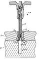
FIG. 1A is a cross sectional view of a ball lock pin received in an exemplary press fit bushing assembly;
FIG. 1B is a cross sectional view of details of the bushing assembly of FIG. 1A;
FIG. 2A is a cross sectional view of a ball lock pin received in an exemplary serrated press fit bushing assembly;
FIG. 2B is a cross sectional view of details of the bushing assembly of FIG. 2A;
FIG. 3A is a cross sectional view of a ball lock pin received in an exemplary diamond knurl bushing assembly;
FIG. 3B is a cross sectional view of details of the bushing assembly of FIG. 3A;
FIG. 4A is a cross sectional view of a ball lock pin received in an exemplary threaded key insert bushing assembly;
FIG. 4B is a cross sectional view of details of the bushing assembly of FIG. 4A;
FIG. 5A is a cross sectional view of a ball lock pin received in an exemplary template bushing assembly;
FIGS. 5B and 5C are cross sectional views of details of the bushing assembly of FIG. 5A;
FIG. 6A is a cross sectional view of a tapered ball lock pin received in an exemplary locking press fit bushing assembly;
FIGS. 6B and 6C are plan views of details of the bushing assembly of FIG. 6A;
FIG. 7A is a cross sectional view of a tapered ball lock pin received in an exemplary locking serrated press fit bushing assembly;
FIGS. 7B and 7C are plan views of details of the bushing assembly of FIG. 7A;
FIG. 8A is a cross sectional view of a tapered ball lock pin received in an exemplary locking diamond knurl bushing assembly;
FIGS. 8B and 8C are plan views of details of the bushing assembly of FIG. 8A;
FIG. 9A is a cross sectional view of a tapered ball lock pin received in an exemplary locking threaded key insert bushing assembly;
FIGS. 9B and 9C are plan views of details of the bushing assembly of FIG. 9A;
FIG. 10A is a cross sectional view of a tapered ball lock pin received in an exemplary locking template bushing assembly;
FIGS. 10B, 10C, and 10D are plan views of details of the bushing assembly of FIG. 10A; and
FIGS. 11A and 11B are perspective views of a locking pin inserted in different positions in two objects.
DETAILED DESCRIPTION
By way of overview, an exemplary retaining assembly for a ball lock pin includes a bushing assembly configured to attachably engage an object. The bushing assembly has an inner surface and an outer surface. The inner surface defines an engagement portion configured to receive locking balls urged therein in engagement. The outer surface is configured to be received within the object. The bushing assembly can include any suitable bushing member as desired for a particular application, such as a press fit bushing, a serrated press fit bushing, a diamond knurl bushing, a key insert bushing, a template bushing, and the like. If desired, the bushing assembly can be a lock bushing configured to receive therein a lock ring. The lock ring can be inserted into the lock bushing and around a tapered portion of a shaft of a ball lock pin to help prevent the ball lock pin from being removed from the bushing assembly.
Referring now to FIGS. 1A and 1B, a ball lock pin 10 is received in engagement in an exemplary bushing 12. The ball lock pin 10 suitably is any known ball lock pin as desired. Locking balls 14 are disposed on a shaft 16 in a known manner such that the locking balls 14 can be urged outwardly to engage a workpiece as desired. Ball lock pins are well known in the art, and therefore a detailed description of construction and operation of the ball lock pin 10 is not necessary for an understanding.
In an exemplary embodiment, the bushing 12 is a press fit bushing. The bushing 12 has a surface 18 that is configured to be press fit into a surface 20 of an object 22. The object 22 may be any object as desired for a particular application and is not intended to be limited in any manner whatsoever.
The bushing 12 has a surface 24 that is configured to receive therein the shaft 16. An engagement portion 26, such as without limitation a concave radial groove, is defined in the surface 24. The engagement portion 26 is sized to receive therein the locking balls 14 when the locking balls 14 are urged outwardly. The locking balls 14 engage the engagement portion 26 to retain the ball lock pin 10 in the bushing 12. Because the bushing 12 is press fit into the object 22, the ball lock pin 10 thus remains with the object 22. By keeping the ball lock pin 10 with the object 22, the bushing 12 helps prevent the ball lock pin 10 from being dropped or possibly becoming lost.
With the ball lock pin 10 engaged within the bushing 12 as described above, the object 22 may be aligned with an object 28. The object 28 may be any object as desired for a particular application and is not intended to be limited in any manner whatsoever. The object 28 has a surface 30 that defines an engagement portion 32, such as a concave radial groove, as described above for the engagement portion 26. The shaft 16 can be inserted into the object 28 and the locking balls 14 can be urged outwardly to engage the engagement portion 32 in the same manner as described above, Thus, the ball lock pin 10 can attach the objects 22 and 28.
Referring now to FIGS. 2A and 2B, the ball lock pin 10 is received in engagement in an exemplary bushing 12A. The bushing 12A is a serrated press fit bushing that has a serrated surface 18A that is press fit into the surface 20 of the object 22. All other details of the bushing 12A are the same as the bushing 12 (FIGS. 1A and 1B) set forth above, and details of the ball lock pin 10 (FIG. 1A) and the objects 22 and 28 (FIG. 1A) are set forth above. Therefore, their repetition is not necessary for an understanding Like reference numbers refer to the same features described above.
Referring now to FIGS. 3A and 3B, the ball lock pin 10 is received in engagement in an exemplary bushing 12B. The bushing 12B is a diamond knurl bushing that has a diamond knurl surface 18B that is bonded with the surface 20 of the object 22 with a potting compound (not shown). All other details of the bushing 12B are the same as the bushing 12 (FIGS. 1A and 1B) set forth above, and details of the ball lock pin 10 (FIG. 1A) and the objects 22 and 28 (FIG. 1A) are set forth above. Therefore, their repetition is not necessary for an understanding. Like reference numbers refer to the same features described above.
Referring now to FIGS. 4A and 4B, the ball lock pin 10 is received in engagement in an exemplary bushing 12C. The bushing 12C is a threaded key insert bushing that has a threaded surface 18C that threadedly engages a threaded surface 20C of an object 22C. Key inserts 34 are provided to stake the bushing 12C to the object 22C. All other details of the bushing 12B and the object 22C (FIG. 1A) are the same as the bushing 12 (FIGS. 1A and 1B) and the object 22 (FIG. 1A) set forth above, and details of the ball lock pin 10 (FIG. 1A) and the object 28 (FIG. 1A) are set forth above. Therefore, their repetition is not necessary for an understanding. Like reference numbers refer to the same features described above.
Referring now to FIGS. 5A, 5B, and 5C, the ball lock pin 10 is received in engagement in an exemplary bushing 12D. The bushing 12D is a template bushing that is made up of a template bushing member 13 and a locking sleeve 15. The template bushing member 13 defines the surface 24 and the engagement portion 26. The template bushing member 13 also defines a threaded surface 17 and an engagement land 21. The locking sleeve 15 defines a threaded surface 19, an engagement surface 23, and an outer surface 25. The template bushing member 13 is received in a counter-sunk opening in the object 22 such that a top surface of the engagement land 21 contacts a surface of the counter-sunk opening of the object 22. The locking sleeve 15 is threaded onto the template bushing member 13. The threaded surface 19 threadedly engages the threaded surface 17 until the engagement surface 23 of the locking sleeve 15 engages a top surface of the object 22, thereby attaching the template bushing 12D to the object 22. Details of the ball lock pin 10 (FIG. 1A) and the objects 22 and 28 (FIG. 1A) are set forth above. Therefore, their repetition is not necessary for an understanding Like reference numbers refer to the same features described above.
Referring now to FIGS. 6A, 6B, and 6C, a ball lock pin 10′ is received in engagement in an exemplary locking press fit bushing 12′. A portion 36 of the shaft 16 of the ball lock pin 10′ is tapered, such as by milling on a mill or other suitable method. The bushing 12′ defines a radial lock groove 38 that is sized to receive therein a lock ring 40. The lock ring 40 can be inserted into the lock groove 38 around the tapered portion 36 to help prevent the ball lock pin 10′ from being removed from the bushing 12′. All other details of the bushing 12′ and the ball lock pin 10′ are the same as the bushing 12 (FIGS. 1A and 1B) and the ball lock pin 10 (FIG. 1A) set forth above, and details of the objects 22 and 28 (FIG. 1A) are set forth above. Therefore, their repetition is not necessary for an understanding Like reference numbers refer to the same features described above.
Referring now to FIGS. 7A, 7B, and 7C, the ball lock pin 10′ is received in engagement in an exemplary locking serrated press fit bushing 12A′. The bushing 12A′ defines the radial lock groove 38 that is sized to receive therein the lock ring 40. The lock ring 40 can be inserted into the lock groove 38 around the tapered portion 36 to help prevent the ball lock pin 10′ from being removed from the bushing 12A′. All other details of the bushing 12A′ are the same as the bushing 12A (FIGS. 2A and 2B) set forth above, and details of ball lock pin 10′ (FIG. 6A) and the objects 22 and 28 (FIG. 1A) are set forth above. Therefore, their repetition is not necessary for an understanding. Like reference numbers refer to the same features described above.
Referring now to FIGS. 8A, 8B, and 8C, the ball lock pin 10′ is received in engagement in an exemplary locking diamond knurl bushing 12B′. The bushing 12B′ defines the radial lock groove 38 that is sized to receive therein the lock ring 40. The lock ring 40 can be inserted into the lock groove 38 around the tapered portion 36 to help prevent the ball lock pin 10′ from being removed from the bushing 12B′. All other details of the bushing 12B′ are the same as the bushing 12B (FIGS. 3A and 3B) set forth above, and details of ball lock pin 10′ (FIG. 6A) and the objects 22 and 28 (FIG. 1A) are set forth above. Therefore, their repetition is not necessary for an understanding. Like reference numbers refer to the same features described above.
Referring now to FIGS. 9A, 9B, and 9C, the ball lock pin 10′ is received in engagement in an exemplary locking threaded key insert bushing 12C′. The bushing 12C′ defines the radial lock groove 38 that is sized to receive therein the lock ring 40. The lock ring 40 can be inserted into the lock groove 38 around the tapered portion 36 to help prevent the ball lock pin 10′ from being removed from the bushing 12C′. All other details of the bushing 12C′ are the same as the bushing 12C (FIGS. 4A and 4B) set forth above, and details of ball lock pin 10′ (FIG. 6A) and the objects 22 and 28 (FIG. 1A) are set forth above. Therefore, their repetition is not necessary for an understanding. Like reference numbers refer to the same features described above.
Referring now to FIGS. 10A, 10B, 10C, and 10D, the ball lock pin 10′ is received in engagement in an exemplary locking template bushing 12D′. A template bushing member 13′ defines the radial lock groove 38 that is sized to receive therein the lock ring 40. The lock ring 40 can be inserted into the lock groove 38 around the tapered portion 36 to help prevent the ball lock pin 10′ from being removed from the bushing 12D′. All other details of the bushing 12D′ are the same as the bushing 12D (FIGS. 5A, 5B, and 5C) set forth above, and details of ball lock pin 10′ (FIG. 6A) and the objects 22 and 28 (FIG. 1A) are set forth above. Therefore, their repetition is not necessary for an understanding Like reference numbers refer to the same features described above.
Referring now to FIG. 11A, the ball lock pin 10 or 10′ can be held within the object 22 and the object 22 (with the ball lock pin 10 or 10′ held therein) can be brought to the object. Because the ball lock pin 10 or 10′ engages any of the exemplary bushings (not shown for purposes of clarity) contemplated herein, a reduction can be made in probability of the ball lock pin 10 or 10′ being dropped or possibly lost while in transport to the object 28. With the ball lock pin 10 or 10′ engaged within the bushing (not shown), the object 22 may be aligned with the object 28.
Referring now to FIG. 11B, the shaft 16 can be inserted into the object 28 and the locking balls 14 can be urged outwardly to engage the engagement portion (not shown for purposes of clarity) in the same manner as described above, Thus, the ball lock pin 10 can attach the objects 22 and 28.
It is again emphasized that the objects 22 and 28 may be any objects as desired for a particular application and are not intended to be limited in any manner whatsoever.
While a number of exemplary embodiments and aspects have been illustrated and discussed above, those of skill in the art will recognize certain modifications, permutations, additions, and sub-combinations thereof. It is therefore intended that the following appended claims and claims hereafter introduced are interpreted to include all such modifications, permutations, additions, and sub-combinations as are within their true spirit and scope.

Claims (20)

1. A method of attaching a ball lock pin, the method comprising:
inserting a bushing assembly in a first object such that an outer surface of the bushing assembly is received within the first object;
inserting, into the bushing assembly, a plurality of locking balls disposed on a shaft of the ball lock pin;
outwardly urging the plurality of locking balls to engage a first engagement portion of an inner surface of the bushing assembly; and
the ball lock pin passing through an open end of the bushing assembly.
2. The method of claim 1, further comprising:
aligning the first object with a second object such that the shaft of the ball lock pin is receivable in the second object;
inserting, into the second object, the plurality of locking balls; and
outwardly urging the plurality of locking balls to engage a second engagement portion of an inner surface of the second object.
3. The method of claim 2 further comprising:
responsive to the plurality of locking balls engaging the second engagement portion of the inner surface of the second object, withdrawing the ball lock pin until the plurality of locking balls engage the first engagement portion, wherein the ball lock pin is secured to the first object when the ball lock pin engages only the inner surface of the bushing assembly.
4. The method of claim 2, wherein engaging the plurality of locking balls with the second engagement portion secures the first object to the second object.
5. The method of claim 1, wherein the step of inserting the bushing assembly in the first object comprises:
inserting the bushing assembly in the first object to attachably engage the first object such that the outer surface of the bushing assembly is received within the first object.
6. The method of claim 1, wherein the inner surface of the bushing assembly defines the first engagement portion in which the first engagement portion includes a concave groove shaped to at least partially receive the plurality of locking balls, and wherein the outer surface of the bushing assembly is shaped to be received within an opening in the first object and supports a plurality of serrations that extend longitudinally between the opposing ends of the bushing assembly.
7. The method of claim 6, wherein the concave groove is a first radial groove and further comprising:
inserting a lock pin in a second radial groove of the bushing assembly after inserting the plurality of locking balls into the bushing assembly to prevent the plurality of locking balls from being removed from the bushing assembly.
8. The method of claim 1, wherein the step of inserting the bushing assembly in the first object such that the outer surface of the bushing assembly is received within the first object comprises:
inserting the bushing assembly in the first object such that the outer surface of the bushing assembly is press fit into the first object to be received within the first object.
9. The method of claim 1, wherein the bushing assembly further comprises a body having a first length in which the first length of the body of the bushing assembly is configured to be shorter than a second length of the shaft of the ball lock pin, wherein the shaft of the ball lock pin is configured to extend through the body of the bushing assembly and beyond the body of the bushing assembly at one or more of the opposing ends of the bushing assembly.
10. The method of claim 1 further comprising:
securing the outer surface of the bushing assembly to the first object.
11. A method of attaching a ball lock pin, the method comprising:
inserting a bushing assembly in a first object such that an outer surface of the bushing assembly is received within the first object;
inserting, into the bushing assembly, a plurality of locking balls disposed on a shaft of the ball lock pin;
outwardly urging the plurality of locking balls to engage a first engagement portion of an inner surface of the bushing assembly;
aligning the first object with a second object such that the shaft of the ball lock pin is receivable in the second object;
inserting, into the second object, the plurality of locking balls; and
outwardly urging the plurality of locking balls to engage a second engagement portion of an inner surface of the second object.
12. The method of claim 11, wherein the step of inserting the bushing assembly in the first object comprises:
inserting the bushing assembly in the first object to attachably engage the first object such that the outer surface of the bushing assembly is received within the first object.
13. The method of claim 11, wherein the bushing assembly comprises opposing ends in which each of the opposing ends is open and sized for the ball lock pin to pass through the bushing assembly.
14. The method of claim 13, wherein the inner surface of the bushing assembly defines the first engagement portion in which the first engagement portion includes a concave groove shaped to at least partially receive the plurality of locking balls, and wherein the outer surface of the bushing assembly is shaped to be received within an opening in the first object and supports a plurality of serrations that extend longitudinally between the opposing ends of the bushing assembly.
15. The method of claim 14, wherein the concave groove is a first radial groove and further comprising:
inserting a lock pin in a second radial groove of the bushing assembly after inserting the plurality of locking balls into the bushing assembly to prevent the plurality of locking balls from being removed from the bushing assembly.
16. The method of claim 13, wherein the bushing assembly further comprises a body having a first length in which the first length of the body of the bushing assembly is configured to be shorter than a second length of the shaft of the ball lock pin, wherein the shaft of the ball lock pin is configured to extend through the body of the bushing assembly and beyond the body of the bushing assembly at one or more of the opposing ends of the bushing assembly.
17. The method of claim 11, wherein the step of inserting the bushing assembly in the first object such that the outer surface of the bushing assembly is received within the first object comprises:
inserting the bushing assembly in the first object such that the outer surface of the bushing assembly is press fit into the first object to be received within the first object.
18. The method of claim 11 further comprising:
responsive to the plurality of locking balls engaging the second engagement portion of the inner surface of the second object, withdrawing the ball lock pin until the plurality of locking balls engage the first engagement portion, wherein the ball lock pin is secured to the first object when the ball lock pin engages only the inner surface of the bushing assembly.
19. The method of claim 11, wherein engaging the plurality of locking balls with the second engagement portion secures the first object to the second object.
20. The method of claim 11 further comprising:
securing the outer surface of the bushing assembly to the first object.
US12/787,045 2006-12-21 2010-05-25 Method of attaching a ball lock pin Expired - Fee Related US7854053B2 (en)

Priority Applications (1)

Application Number Priority Date Filing Date Title
US12/787,045 US7854053B2 (en) 2006-12-21 2010-05-25 Method of attaching a ball lock pin

Applications Claiming Priority (2)

Application Number Priority Date Filing Date Title
US11/644,810 US7736109B2 (en) 2006-12-21 2006-12-21 Multi-position ball lock/quick release pin bushing/retainer
US12/787,045 US7854053B2 (en) 2006-12-21 2010-05-25 Method of attaching a ball lock pin

Related Parent Applications (1)

Application Number Title Priority Date Filing Date
US11/644,810 Division US7736109B2 (en) 2006-12-21 2006-12-21 Multi-position ball lock/quick release pin bushing/retainer

Publications (2)

Publication Number Publication Date
US20100218361A1 US20100218361A1 (en) 2010-09-02
US7854053B2 true US7854053B2 (en) 2010-12-21

Family

ID=39183128

Family Applications (2)

Application Number Title Priority Date Filing Date
US11/644,810 Expired - Fee Related US7736109B2 (en) 2006-12-21 2006-12-21 Multi-position ball lock/quick release pin bushing/retainer
US12/787,045 Expired - Fee Related US7854053B2 (en) 2006-12-21 2010-05-25 Method of attaching a ball lock pin

Family Applications Before (1)

Application Number Title Priority Date Filing Date
US11/644,810 Expired - Fee Related US7736109B2 (en) 2006-12-21 2006-12-21 Multi-position ball lock/quick release pin bushing/retainer

Country Status (2)

Country Link
US (2) US7736109B2 (en)
WO (1) WO2008088417A2 (en)

Cited By (3)

* Cited by examiner, † Cited by third party
Publication number Priority date Publication date Assignee Title
US20090284026A1 (en) * 2008-05-18 2009-11-19 Southco, Inc. T-handle actuator and latch
TWI463077B (en) * 2012-03-05 2014-12-01 Hanwit Prec Ind Ltd Plate - to - board fast positioning device and its assembling method
US9163651B2 (en) 2013-03-14 2015-10-20 Meyer Ostrobrod Concrete anchor

Families Citing this family (8)

* Cited by examiner, † Cited by third party
Publication number Priority date Publication date Assignee Title
NL2001314C2 (en) * 2008-02-22 2009-08-31 Paul Bolleboom Fastening device as well as a release and placement tool for such a fastening device.
US20100150648A1 (en) * 2008-12-15 2010-06-17 Robert Arnold Judge Quick-connect joints and related methods
US9028184B2 (en) * 2012-10-19 2015-05-12 Dennis Bone Protrusion anchor assembly
DE102016112770A1 (en) * 2016-07-12 2018-01-18 Andreas Maier Gmbh & Co. Kg jig
CN107339306A (en) * 2017-07-18 2017-11-10 安徽江淮汽车集团股份有限公司 A kind of dowel device of locking function
CN109290989A (en) * 2018-12-03 2019-02-01 江西洪都航空工业集团有限责任公司 A kind of quick clamping mechanism
US11328842B2 (en) * 2019-10-28 2022-05-10 The Boeing Company Form board preparation for wire bundling
CN110925284A (en) * 2019-12-13 2020-03-27 广东乐思富科技有限公司 Expansion connector

Citations (26)

* Cited by examiner, † Cited by third party
Publication number Priority date Publication date Assignee Title
US1635144A (en) 1926-12-18 1927-07-05 Jr William Grant Stevens Coupling
US2837942A (en) 1955-06-06 1958-06-10 Northrop Aircraft Inc Self locking bushing
US3026749A (en) 1958-01-27 1962-03-27 Rezolin Inc Drill guide bushing
US3349649A (en) 1965-07-26 1967-10-31 Joseph J Mele Press-fit bushing
US3361388A (en) 1966-03-07 1968-01-02 Ryan Aeronautical Co Demountable aircraft with flexible wing
US3391244A (en) 1965-09-14 1968-07-02 John A. Moll Foreign material eliminator and aerial warning marker for overhead conductors
US3521895A (en) 1968-07-24 1970-07-28 Theodore M Smith Tool holder
US3617081A (en) 1970-02-27 1971-11-02 Bio Consultants Inc Latching mechanism
US4168047A (en) 1975-07-03 1979-09-18 R. Alkan & Cie Automatic load carrier and jettisoning system with built-in hoisting means
US4269550A (en) 1980-03-14 1981-05-26 Digiulio Mario Drill bushing for use in a metal tooling plate
US4365535A (en) 1981-01-09 1982-12-28 Herbert Dolowich Quick release locking mechanism
US4741505A (en) 1985-03-22 1988-05-03 Anderson Carl E Scaffolding arrangement
US4843792A (en) 1988-06-27 1989-07-04 Stageright Corporation Socket support and interlock for staging panels
US5002002A (en) 1986-10-03 1991-03-26 Deep Seven Co. Method for securing anchors
US5014037A (en) 1987-12-02 1991-05-07 Mcdonald Gerald H Potentiometer mounting mechanism
US5146655A (en) 1991-10-29 1992-09-15 Gibbs Peter E Safety clamp appliance
US5181725A (en) 1991-12-03 1993-01-26 Leras Nicholas J Soccer shooting training target
US5240086A (en) 1992-05-08 1993-08-31 Electric Mobility Corp. Removable drive train from frame of a personal vehicle
DE4232688A1 (en) 1992-09-29 1994-03-31 Johannes Herkels Detachable push-in connection with plug and socket - has spring-tensioned balls protruding out of connecting plug to engage in socket grooves through effect of compression spring
US5484243A (en) 1993-08-05 1996-01-16 State Of Israel-Ministry Of Defense Armament Development Authority-Rafael Carriage and release mechanism for airborne store
US6019484A (en) 1998-07-27 2000-02-01 Seyler; Christopher M. Portable task lighting device
US6532702B1 (en) 2000-03-21 2003-03-18 Paul J. Scribner Building fixture protection apparatus having protective panels and a plurality of quick connect/disconnect means
US6641343B1 (en) * 2002-12-23 2003-11-04 Avibank Mfg., Inc. Fastener with magnetically actuated positive lock plug insert
US20030219325A1 (en) 2002-05-22 2003-11-27 Dennis Schultz Threaded insert for fasteners
US20050095079A1 (en) 2003-11-03 2005-05-05 Ludwig Beckers Eye bolt
US20060134957A1 (en) 2004-12-22 2006-06-22 Jore Corporation Adjustable stop

Patent Citations (26)

* Cited by examiner, † Cited by third party
Publication number Priority date Publication date Assignee Title
US1635144A (en) 1926-12-18 1927-07-05 Jr William Grant Stevens Coupling
US2837942A (en) 1955-06-06 1958-06-10 Northrop Aircraft Inc Self locking bushing
US3026749A (en) 1958-01-27 1962-03-27 Rezolin Inc Drill guide bushing
US3349649A (en) 1965-07-26 1967-10-31 Joseph J Mele Press-fit bushing
US3391244A (en) 1965-09-14 1968-07-02 John A. Moll Foreign material eliminator and aerial warning marker for overhead conductors
US3361388A (en) 1966-03-07 1968-01-02 Ryan Aeronautical Co Demountable aircraft with flexible wing
US3521895A (en) 1968-07-24 1970-07-28 Theodore M Smith Tool holder
US3617081A (en) 1970-02-27 1971-11-02 Bio Consultants Inc Latching mechanism
US4168047A (en) 1975-07-03 1979-09-18 R. Alkan & Cie Automatic load carrier and jettisoning system with built-in hoisting means
US4269550A (en) 1980-03-14 1981-05-26 Digiulio Mario Drill bushing for use in a metal tooling plate
US4365535A (en) 1981-01-09 1982-12-28 Herbert Dolowich Quick release locking mechanism
US4741505A (en) 1985-03-22 1988-05-03 Anderson Carl E Scaffolding arrangement
US5002002A (en) 1986-10-03 1991-03-26 Deep Seven Co. Method for securing anchors
US5014037A (en) 1987-12-02 1991-05-07 Mcdonald Gerald H Potentiometer mounting mechanism
US4843792A (en) 1988-06-27 1989-07-04 Stageright Corporation Socket support and interlock for staging panels
US5146655A (en) 1991-10-29 1992-09-15 Gibbs Peter E Safety clamp appliance
US5181725A (en) 1991-12-03 1993-01-26 Leras Nicholas J Soccer shooting training target
US5240086A (en) 1992-05-08 1993-08-31 Electric Mobility Corp. Removable drive train from frame of a personal vehicle
DE4232688A1 (en) 1992-09-29 1994-03-31 Johannes Herkels Detachable push-in connection with plug and socket - has spring-tensioned balls protruding out of connecting plug to engage in socket grooves through effect of compression spring
US5484243A (en) 1993-08-05 1996-01-16 State Of Israel-Ministry Of Defense Armament Development Authority-Rafael Carriage and release mechanism for airborne store
US6019484A (en) 1998-07-27 2000-02-01 Seyler; Christopher M. Portable task lighting device
US6532702B1 (en) 2000-03-21 2003-03-18 Paul J. Scribner Building fixture protection apparatus having protective panels and a plurality of quick connect/disconnect means
US20030219325A1 (en) 2002-05-22 2003-11-27 Dennis Schultz Threaded insert for fasteners
US6641343B1 (en) * 2002-12-23 2003-11-04 Avibank Mfg., Inc. Fastener with magnetically actuated positive lock plug insert
US20050095079A1 (en) 2003-11-03 2005-05-05 Ludwig Beckers Eye bolt
US20060134957A1 (en) 2004-12-22 2006-06-22 Jore Corporation Adjustable stop

Cited By (4)

* Cited by examiner, † Cited by third party
Publication number Priority date Publication date Assignee Title
US20090284026A1 (en) * 2008-05-18 2009-11-19 Southco, Inc. T-handle actuator and latch
US8336931B2 (en) * 2008-05-18 2012-12-25 Southco, Inc. T-handle actuator and latch
TWI463077B (en) * 2012-03-05 2014-12-01 Hanwit Prec Ind Ltd Plate - to - board fast positioning device and its assembling method
US9163651B2 (en) 2013-03-14 2015-10-20 Meyer Ostrobrod Concrete anchor

Also Published As

Publication number Publication date
US7736109B2 (en) 2010-06-15
WO2008088417A2 (en) 2008-07-24
US20100218361A1 (en) 2010-09-02
WO2008088417A3 (en) 2009-04-09
US20080152457A1 (en) 2008-06-26

Similar Documents

Publication Publication Date Title
US7854053B2 (en) Method of attaching a ball lock pin
US6311989B1 (en) Chuck for screwdriver inserts
US6623220B2 (en) Quick change mandrel assembly for use with a hole saw and a pilot drill bit
ES2262829T3 (en) FAST MOUNTING SYSTEM FOR PLASTIC ELEMENTS.
US7722303B2 (en) Frangible blind rivet
WO2006096386A3 (en) Collet and lock nut assembly
US8656573B2 (en) Shrink-fit tool with mechanical retention member, and method of mounting a tool to a toolholder
US20160243909A1 (en) Apparatus and method of installing an internal locking ring to reinforce an adjustable trailer hitch
DE10123390A1 (en) Chuck with quick change device
US3641860A (en) Punch retainer assembly
KR20100055445A (en) Blind rivet
EP1099861A3 (en) Locking system
EP2502693B1 (en) Quick change adapter for a hole saw
US2646761A (en) Method of making ball-type writing tips
US20050180839A1 (en) Set screw with NiTi Tip
US20160031017A1 (en) Tool bit holder for power tool
EP0799967A3 (en) Drill bit with a centring drill
US7475466B2 (en) Alignment of body and frame of vehicle
US20160288310A1 (en) Retaining mechanism for telescoping pole
US5341710A (en) Coupling structure and method
US20040200333A1 (en) 360 Degree ball lock groove for a tool assembly
US2917331A (en) Means for securing relatively movable members
WO2013184674A1 (en) Quick change power tool chuck
US20040104545A1 (en) Connection of tool with tool bit
CA2510287A1 (en) Method of securing a rotary cutter to a body of a down hole tool and a rotary cutter assembly

Legal Events

Date Code Title Description
FEPP Fee payment procedure

Free format text: PAYOR NUMBER ASSIGNED (ORIGINAL EVENT CODE: ASPN); ENTITY STATUS OF PATENT OWNER: LARGE ENTITY

STCF Information on status: patent grant

Free format text: PATENTED CASE

FPAY Fee payment

Year of fee payment: 4

MAFP Maintenance fee payment

Free format text: PAYMENT OF MAINTENANCE FEE, 8TH YEAR, LARGE ENTITY (ORIGINAL EVENT CODE: M1552)

Year of fee payment: 8

FEPP Fee payment procedure

Free format text: MAINTENANCE FEE REMINDER MAILED (ORIGINAL EVENT CODE: REM.); ENTITY STATUS OF PATENT OWNER: LARGE ENTITY

LAPS Lapse for failure to pay maintenance fees

Free format text: PATENT EXPIRED FOR FAILURE TO PAY MAINTENANCE FEES (ORIGINAL EVENT CODE: EXP.); ENTITY STATUS OF PATENT OWNER: LARGE ENTITY

STCH Information on status: patent discontinuation

Free format text: PATENT EXPIRED DUE TO NONPAYMENT OF MAINTENANCE FEES UNDER 37 CFR 1.362

FP Lapsed due to failure to pay maintenance fee

Effective date: 20221221