US7835433B2 - Multiple receiving devices determining the sampling rate for received signals using a plurality of sampling rates - Google Patents
Multiple receiving devices determining the sampling rate for received signals using a plurality of sampling rates Download PDFInfo
- Publication number
- US7835433B2 US7835433B2 US11/871,013 US87101307A US7835433B2 US 7835433 B2 US7835433 B2 US 7835433B2 US 87101307 A US87101307 A US 87101307A US 7835433 B2 US7835433 B2 US 7835433B2
- Authority
- US
- United States
- Prior art keywords
- sampling rates
- sampling
- received
- channel
- signal
- Prior art date
- Legal status (The legal status is an assumption and is not a legal conclusion. Google has not performed a legal analysis and makes no representation as to the accuracy of the status listed.)
- Expired - Fee Related, expires
Links
Images


Classifications
-
- H—ELECTRICITY
- H04—ELECTRIC COMMUNICATION TECHNIQUE
- H04B—TRANSMISSION
- H04B1/00—Details of transmission systems, not covered by a single one of groups H04B3/00 - H04B13/00; Details of transmission systems not characterised by the medium used for transmission
- H04B1/69—Spread spectrum techniques
- H04B1/707—Spread spectrum techniques using direct sequence modulation
- H04B1/7073—Synchronisation aspects
- H04B1/7075—Synchronisation aspects with code phase acquisition
- H04B1/70757—Synchronisation aspects with code phase acquisition with increased resolution, i.e. higher than half a chip
Definitions
- the present invention contains subject matter related to Japanese Patent Application JP 2006-278353 filed in the Japanese Patent Office on Oct. 12, 2006, the entire contents of which are incorporated herein by reference.
- the present invention relates to receiver apparatuses, receiving methods, programs, and recording media. More particularly, the present invention relates to a receiver apparatus, a receiving method, a program, and a recording medium, which are capable of improving the reception characteristics.
- CDMA Code Division Multiple Access
- FIG. 1 is a block diagram showing an example of the configuration of a receiver apparatus 1 receiving signals by a channel response estimation method by using the sliding correlation.
- a received signal is input in a sliding correlator 11 .
- the sliding correlator 11 multiplies the received signal by a spread code having a phase T, supplied from a spread code generator 12 .
- the signal resulting from the multiplication is supplied to an integrator 13 .
- the integrator 13 integrates the signal with respect to the period of one spread code, and the integrated signal is supplied to a square circuit 14 .
- the square circuit 14 detects a channel response corresponding to the phase T.
- the output from the square circuit 14 is supplied to a channel response estimator 15 .
- the channel response estimator 15 estimates the entire channel response corresponding to different phases other than the phase T.
- FIG. 2 is a block diagram showing an example of the configuration of a receiver apparatus 21 estimating a channel response by using the correlation.
- a received signal subjected to oversampling in an analog-to-digital (A/D) converter (not shown) is input in a decimator 31 where the signal is downsampled at appropriate sampling intervals.
- the output from the decimator 31 is supplied to a correlation filter 32 where correlation processing (matched filtering) is performed. If the received signal has predetermined correlation, the output from the correlation filter 32 directly represents a channel response. Accordingly, a channel response estimator 33 estimates the entire channel response on the basis of the output from the correlation filter 32 . It is possible to estimate the channel response in a short time by this method.
- FIG. 3 is a block diagram showing an example of the configuration of a receiver apparatus 41 capable of using two correlation filters to estimate individual channel responses only if necessary.
- a received signal is input in a decimator 51 .
- the decimator 51 decimates the received signal at two decimation rates.
- the decimator 51 supplies a decimation output at a higher decimation rate (a lower degree of oversampling) to a correlation filter 52 and supplies a decimation output at a lower decimation rate (a higher degree of oversampling) to a correlation filter 53 .
- the correlation filter 52 roughly estimates channel responses, and the operation of the correlation filter 53 is delayed for a necessary time by using the estimated result by the correlation filter 52 to estimate the channel responses in detail.
- a channel response estimator 54 estimates the entire channel response on the basis of the channel responses estimated by the correlation filter 53 .
- the technologies described above with reference to FIGS. 1 to 3 each detect the maximum value of the impulse response in one chip and does not detect two or more samples per chip.
- MIMO Multiple Input Multiple Output
- SIMO Single Input Multiple Output
- MISO Multiple Input Single Output
- both a transmitter apparatus and a receiver apparatus are provided with multiple antennas or multiple antenna elements (elements each including at least one antenna) to realize multiple transmission lines that are logically independent of each other.
- the receiver apparatus splits a received signal and simultaneously demodulates the signal to achieve both improvement in the frequency usage efficiency and reduction in the error rate owing to the effects of diversity (for example, refer to Motohiko Isaka, December 2003, “MIMO Tsushinro ni Okeru Fugouka to Hennchou (Coding and Modulation in MIMO Channel)”, The Institute of Electronics, Information, and Communication Engineers (IEICE) Transactions A, Vol. J86-A, No. 12 1292-1302).
- the increase in the power consumption, the area of the circuit, and the cost are not preferable to wireless terminals although the characteristics are improved.
- the MIMO in the related art has the trouble in that many antenna elements are necessary to improve the reception characteristics, particularly at the receiver side.
- Small wireless local area network (LAN) terminals or wireless LAN cards are necessary to achieve such functions.
- mounting many antenna elements in the small wireless LAN terminals or wireless LAN cards in order to improve the reception characteristics makes the reduction in the size of the apparatuses or cards difficult.
- a receiver apparatus includes a plurality of signal receiving means; a plurality of channel signal outputting means for sampling signals received by the plurality of signal receiving means at sampling rates switched within a predetermined range or between multiple values and outputting channel signals; control means for controlling the sampling rates in the plurality of channel signal outputting means; response estimating means for estimating responses on the basis of the channel signals output from the plurality of channel signal outputting means; evaluating means for evaluating reception characteristics on the basis of the responses estimated by the response estimating means; and determining means for determining the sampling rates in the plurality of channel signal outputting means on the basis of the reception characteristics at the multiple sampling rates evaluated by the evaluating means.
- the control means may control the sampling rates in the plurality of channel signal outputting means so that the response estimating means estimates the responses at the multiple sampling rates, the response estimating means may estimate the responses at the multiple sampling rates in the plurality of channel signal outputting means, the evaluating means may evaluate the reception characteristics on the basis of the responses at the multiple sampling rates in the plurality of channel signal outputting means, and the determining means may determine a predetermined sampling rate at which each channel signal outputting means samples a signal corresponding to the main information, on the basis of the reception characteristics evaluated by the evaluating means.
- the control means may control the sampling rates in the plurality of channel signal outputting means so as to be the predetermined sampling rates.
- the signals may be sampled at different sampling points at the different sampling rates in the plurality of channel signal outputting means.
- the evaluating means may evaluate the reception characteristics in all the combinations of the multiple sampling rates in the plurality of channel signal outputting means.
- the determining means may determine a predetermined combination of the sampling rates in which the plurality of channel signal outputting means sample the signals corresponding to the main information on the basis of the reception characteristics evaluated by the evaluating means in all the combinations of the multiple sampling rates in the plurality of channel signal outputting means.
- the determining means may determine a combination of the sampling rates having the highest evaluation value, among the values of the reception characteristics evaluated by the evaluating means in all the combinations of the multiple sampling rates in the plurality of channel signal outputting means, to be the combination of the sampling rates in which the plurality of channel signal outputting means sample the signals corresponding to the main information.
- the determining means may compare the values of the reception characteristics in all the combinations of the multiple sampling rates in the plurality of channel signal outputting means, evaluated by the evaluating means, with a predetermined threshold value, and may determine a combination having the smallest amount of power consumption, among the combinations providing the evaluated values higher than the predetermined value, to be the combination of the sampling rates in which the plurality of channel signal outputting means sample the signals corresponding to the main information.
- Each channel signal outputting means may include analog-to-digital converting means for oversampling the received signal and converting the signal into a digital signal and rate varying means for varying a rate of the digital signal resulting from the conversion by the analog-to-digital converting means and outputting the channel signal at the sampling rate controlled by the control means.
- the receiver apparatus may further include demodulating means for demodulating the received signals on the basis of the responses estimated by the response estimating means.
- the receiver apparatus may further include combination control means for controlling the number of fingers and a tap coefficient in RAKE combination on the basis of the responses estimated by the response estimating means.
- the demodulating means may separate multiple signals transmitted through multiple antennas to demodulate the separated signals.
- the receiver apparatus may further include combination control means for controlling a diversity factor on the basis of the responses estimated by the response estimating means.
- a receiving method for a receiver apparatus receiving signals with a plurality of signal receiving means including different antennas includes the steps of, during a period when signals corresponding to secondary information necessary for receiving main information are received before the main information is received, sampling the received signals corresponding to the secondary information, received through the antennas in the plurality of signal receiving means, at multiple sampling rates controlled so as to estimate responses at the multiple sampling rates; estimating the responses of the received signals corresponding to the secondary information sampled at the multiple sampling rates; evaluating reception characteristics at the multiple sampling rates of the received signals received by the plurality of signal receiving means on the basis of the estimated responses at the multiple sampling rates; and determining a predetermined sampling rate at which each signal receiving means samples the signal corresponding to the main information, on the basis of the evaluated reception characteristics.
- the method includes the steps of, during a period when signals corresponding to the main information are received, controlling the sampling rates at which the received signals corresponding to the main information are sampled so as to be the predetermined sampling rates determined for every signal receiving means and sampling the received signals corresponding to the main information, received through the multiple antennas in the plurality of signal receiving means, at the predetermined sampling rates.
- a computer-executable program controlling processing of received signals includes the steps of, during a period when signals corresponding to secondary information necessary for receiving main information are received before the main information is received, controlling sampling of the received signals corresponding to the secondary information, received through multiple antennas in a plurality of signal receiving means, at multiple sampling rates controlled so as to estimate responses at the multiple sampling rates; estimating the responses of the received signals corresponding to the secondary information sampled at the multiple sampling rates; evaluating reception characteristics at the multiple sampling rates of the received signals received by the plurality of signal receiving means on the basis of the estimated responses at the multiple sampling rates; and determining a predetermined sampling rate at which each signal receiving means samples the signal corresponding to the main information on the basis of the evaluated reception characteristics.
- the program includes the steps of, during a period when signals corresponding to the main information are received, controlling the sampling rates at which the received signals corresponding to the main information are sampled so as to be the predetermined sampling rates determined for every signal receiving means and controlling sampling of the received signals corresponding to the main information, received through the multiple antennas in the plurality of signal receiving means, at the predetermined sampling rates.
- the sampling rates at which the signals received by the plurality of signal receiving means are sampled are controlled so as to estimate the responses at the multiple sampling rates, the responses are estimated, and the reception characteristics are evaluated on the basis of the estimated responses.
- the predetermined sampling rate at which each signal receiving means samples the signal corresponding to the main information is determined on the basis of the evaluated reception characteristics, and the sampling rate at which each signal receiving means samples the signal corresponding to the main information is controlled so as to be the determined predetermined sampling rate.
- a network means a mechanism over which at least two apparatus are connected and in which information can be transmitted from one apparatus to another apparatus.
- the apparatuses communicated with each other over the network may be separated from each other or may be internal block composing one apparatus.
- the communication may be wireless communication or wired communication.
- the wireless communication and the wired communication may be mixed in the communication, that is, the wireless communication may be performed in some sections and the wired communication may be performed in other sections.
- the wired communication may be established from one apparatus to the other apparatus and the wireless communication may be established from the other apparatus to the one apparatus.
- the receiver apparatus may be an independent apparatus or may be a block performing the reception process in a transmission and reception apparatus or an information processing apparatus.
- the sampling rate providing superior reception characteristics is selected from the multiple sampling rates for every sampling of a signal received by each signal receiving means and the sampling rate at the reception is controlled. Accordingly, it is possible to improve the reception characteristics while reducing increases in the power consumption, in the area of the circuit, and in the cost.
- FIG. 1 is a block diagram showing an example of the configuration of a receiver apparatus in related art
- FIG. 2 is a block diagram showing an example of the configuration of another receiver apparatus in the related art
- FIG. 3 is a block diagram showing an example of the configuration of another receiver apparatus in the related art
- FIG. 4 is a block diagram showing an example of the configuration of a receiver apparatus according to an embodiment of the present invention.
- FIG. 5 is a block diagram showing an example of the configuration of a channel filter in FIG. 4 ;
- FIG. 6 is a functional block diagram showing an example of the function of a channel response estimation unit in FIG. 4 ;
- FIG. 7 illustrates estimation of an response
- FIG. 8 is a graph illustrating an output from a correlation filter when an impulse response of four pulses exists
- FIG. 9 is a graph illustrating examples of sampling points at a sampling rate of one sample per chip
- FIG. 10 is a graph illustrating examples of sampling points at a sampling rate of two samples per chip
- FIG. 11 illustrates an example of a channel response
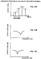
- FIGS. 12A and 12B illustrate frequency characteristics at a sampling rate of one sample per symbol
- FIGS. 13A to 13C illustrate frequency characteristics at a sampling rate of two samples per symbol
- FIG. 14 is a graph illustrating an example of a channel response when received signal pulses have a triangle correlation waveform
- FIG. 15 is a graph illustrating a channel impulse response at the sampling rate of one sample per symbol in the example in FIG. 14 ;
- FIG. 16 is a graph illustrating a frequency response in the example shown in FIG. 15 ;
- FIG. 17 is a graph illustrating a channel impulse response of the first sample at the sampling rate of two samples per symbol in the example in FIG. 14 ;
- FIG. 18 is a graph illustrating a frequency response in the example shown in FIG. 17 ;
- FIG. 19 is a graph illustrating a channel impulse response of the second sample at the sampling rate of two samples per symbol in the example in FIG. 14 ;
- FIG. 20 is a graph illustrating a frequency response in the example shown in FIG. 19 ;
- FIG. 21 is a flowchart showing an example of a reception process at reception of OFDM signals according to an embodiment of the present invention.
- FIG. 22 is a flowchart showing an example of a reception process at reception of DS/SS signals according to an embodiment of the present invention.
- FIG. 23 is a block diagram showing an example of the configuration of a personal computer according to an embodiment of the present invention.
- a receiver apparatus includes, for example, multiple signal receiving units each including A/D converters each oversampling one symbol and channel filters capable of changing the degree of oversampling, a channel response estimation unit, and a signal processing unit performing signal combination and demodulation.
- a signal received through the antenna of one of the multiple signal receiving units passes through, for example, a bandpass filter and an amplifier, is split by a splitter, and is supplied to the two A/D converters corresponding to an inphase (I) signal component and a quadrature (Q) signal component.
- the two A/D converters each oversample one symbol.
- the oversampled signals are supplied to the two channel filters corresponding to the I signal component and the Q signal component.
- the channel filters each extract an aliasing component of the received signal.
- the signals that are received through the multiple antennas and that are output from the two channel filters in each signal receiving unit are used to estimate a channel response, and the demodulation is performed on the basis of the estimated channel response.
- an increase in the number of the reception antennas obviously improves the reception characteristics.
- the increase in the number of the reception antennas makes a reduction in the size of the apparatus difficult and increases the cost.
- an increase in the sampling rate obviously improves the characteristics.
- parallel signal processing is adapted, the area where the circuit is mounted is increased and the cost is also increased.
- the sampling rate of the output from the channel filter is not fixed, that is, is variable.
- the sampling rates may be set to different values for different signal receiving units.
- the above-described receiver apparatus determines which sampling rate, among the sampling rates that can be set for the outputs from the channel filters in each signal receiving unit, provides superior reception characteristics on the basis of the channel response of each transmission antenna when multiple transmission antennas are used and on the basis of the channel response of the signal transmitted through the transmission antenna when one transmission antenna is used.
- the receiver apparatus sets the sampling rate providing the superior reception characteristics for each signal receiving unit to perform communication.
- the sampling rate may be set so as to satisfy a request for the amount of power consumption.
- each signal receiving unit have different sampling points at the different sampling rates that can be set in order to improve the reception characteristics.
- FIG. 4 is a block diagram showing an example of the configuration of a receiver apparatus 81 including multiple receiving units capable of switching between sampling rates, according to an embodiment of the present invention.
- the receiver apparatus 81 includes receiver units of N number from a receiver unit 91 - 1 to a receiver unit 91 -N, a channel response estimation unit 107 , and a signal combination-demodulation unit 108 .
- a signal subjected signal combination and demodulation is processed in a digital signal processing unit (not shown) which is provided downstream of the above components. Since the receiver units 91 - 1 to 91 -N basically have similar configurations, the configuration of the receiver unit 91 - 1 will now be described with reference to FIG. 4 .
- the receiver unit 91 - 1 includes an antenna 101 - 1 , a bandpass filter (BPF) 102 - 1 , a low noise amplifier (LNA) 103 - 1 , a splitter 104 - 1 , ⁇ A/D converters 105 - 1 - 1 and 105 - 2 - 1 , and channel filters 106 - 1 - 1 and 106 - 2 - 1 .
- BPF bandpass filter
- LNA low noise amplifier
- a signal received through the antenna 101 - 1 is supplied to the BPF 102 - 1 .
- the BPF 102 - 1 filters out signals outside a predetermined frequency range.
- the LNA 103 - 1 amplifies the supplied radio-frequency (RF) signal with a low noise.
- the splitter 104 - 1 splits the amplified RF signal and supplies the split signals to the ⁇ A/D converters 105 - 1 - 1 and 105 - 2 - 1 .
- the ⁇ A/D converters 105 - 1 - 1 and 105 - 2 - 1 each convert the supplied RF signal into a bit string of one bit to perform high-order oversampling.
- the oversampled signals are supplied to the channel filters 106 - 1 - 1 and 106 - 2 - 1 .
- the channel filters 106 - 1 - 1 and 106 - 2 - 1 each adjust the sampling rate before the demodulation and perform filtering to extract the aliasing component of the received signal.
- the channel filters 106 - 1 - 1 and 106 - 2 - 1 adjust the sampling rates (change the degree of oversampling) under the control of the channel response estimation unit 107 .
- multiple sampling rates that can be set may be set in advance and may be adjusted to any sampling rate under the control of the channel response estimation unit 107 .
- the channel filters 106 - 1 - 1 and 106 - 2 - 1 may use any sampling rate within a predetermined range under the control of the channel response estimation unit 107 . The adjustment of the sampling rate will be described in detail below.
- the inphase (I) signal output from the channel filter 106 - 1 - 1 and the quadrature (Q) signal output from the channel filter 106 - 2 - 1 are supplied to the channel response estimation unit 107 and the signal combination-demodulation unit 108 .
- the antennas 101 - 1 to 101 -N are collectively referred to as the antenna 101 if it is not necessary to differentiate the individual antennas.
- the BPFs 102 - 1 to 102 -N are collectively referred to as the BPF 102 if it is not necessary to differentiate the individual BPFs.
- the LNAs 103 - 1 to 103 -N are collectively referred to as the LNA 103 if it is not necessary to differentiate the individual LNAs.
- the splitters 104 - 1 to 104 -N are collectively referred to as the splitter 104 if it is not necessary to differentiate the individual splitters.
- the ⁇ A/D converters 105 - 1 - 1 , the ⁇ A/D converter 105 - 2 - 1 , . . . ,the ⁇ A/D converter 105 - 1 -N, and the ⁇ A/D converter 105 - 2 -N are collectively referred to as the ⁇ A/D converter 105 if it is not necessary to differentiate the individual ⁇ A/D converters.
- the channel filter 106 - 1 - 1 , the channel filter 106 - 2 - 1 , . . . , the channel filter 106 - 1 -N, and the channel filter 106 - 2 -N are collectively referred to as the channel filter 106 if it is not necessary to differentiate the individual channel filters.
- the channel response estimation unit 107 estimates a channel response from the output from the channel filter 106 .
- the channel response estimation unit 107 changes the degree of oversampling in the channel filter 106 on the basis of the estimated channel response.
- the channel response estimation unit 107 supplies a control signal used for controlling, for example, diversity combination, RAKE combination, or MIMO signal demodulation to the signal combination-demodulation unit 108 .
- the signal combination-demodulation unit 108 demodulates the oversampled signal by a predetermined method corresponding to the format of the received signal. The function of the channel response estimation unit 107 will be described in detail below with reference to FIG. 6 .
- the ⁇ A/D converter 105 is used for the analog-to-digital conversion in the receiver apparatus 81 shown in FIG. 4
- an A/D converter performing A/D conversion other than ⁇ A/D conversion may be used.
- the oversampling is performed in the A/D conversion and the sampling rate before the demodulation is adjusted in the channel filter 106 in the receiver apparatus 81 shown in FIG. 4
- the sampling rate may be adjusted in the A/D conversion.
- the sampling rate may be adjusted in the A/D conversion after frequency conversion is performed in a mixer, as in manners commonly adapted.
- the ⁇ A/D converters 105 is used for the A/D conversion and the channel filter 106 adjusts the sampling rate before the demodulation in the receiver apparatus 81 shown in FIG. 4
- another configuration may be adapted as long as the function of receiving an analog signal and converting the analog signal into a digital signal having a sampling rate among multiple predetermined sampling rates or a sampling rate within a predetermined range under the control of the channel response estimation unit 107 is achieved.
- a method is normally used in which the sampling rate is upsampled to a clock rate realizing the least common multiple of the rates of two clocks, the signal is caused to pass through a filter for removing the aliasing component, and the sampling rate is downsampled (for example, refer to P. P. Vaidyanathan “Multirate systems and filter banks”, PRENTICE-HALL PTR).
- the method can be impractical for the power consumption and the area of the circuit in view of the mounting of a digital filter downstream of the channel filter 106 .
- the effect of the aliasing is caused if the symbol yielded in the above manner is further decimated, the decimation is acceptable as long as the aliasing component is attenuated to an allowable range by the SINC filter. If a desired signal is a narrowband signal and no aliasing component interferes in the bandwidth, the effect of the aliasing can be lessened in the downstream digital filter.
- the above system is an equivalence of provision of two-stage SINC filters and the mounting cost of the system becomes very low.
- limitation of an anti-aliasing filter to the SINC filter causes problems including an insufficient amount of attenuation of the aliasing component, attenuation of an amplitude within a desired bandwidth, or the necessity for consideration of degradation of the characteristics.
- the notch frequency of the first-stage SINC filter becomes high in the above case, the amount of attenuation in the desired bandwidth is decreased.
- the channel filter 106 may have a configuration shown in FIG. 5 .
- an low-pass filter (LPF) 121 filters out high-frequency signal components having frequencies higher than a predetermined frequency range.
- a decimator 122 reduces the sampling rate of the input signal by a predetermined rate X 1 (multiplies the sampling rate thereof by 1/X 1 ). Since the decimator 122 picks up and outputs a signal sampled at a sampling rate Fs 1 at predetermined timing, the sampling points of an output signal at a predetermined sampling rate Fs 2 is determined in accordance with the time when the signal is picked up.
- a sampling rate converter (SRC) 123 complements the yielded data at a rate of Fs 2 /(Fs 3 ⁇ Fs 2 ) where “Fs 2 ” denotes the sampling rate of the input signal and “Fs 3 ” denotes the sampling rate of the output signal.
- a SINC filter 124 performs moving averaging.
- the SINC filter 124 may be omitted in the channel filter 106 depending on error vector magnitude (EVM) measurements that are required.
- EVM error vector magnitude
- BPSK binary phase shift keying
- QPSK quadrature phase shift keying
- 16QAM 16 quadrature amplitude modulation
- 64QAM 64QAM
- a decimator 125 reduces the sampling rate of the input signal by a predetermined rate X 2 (multiplies the sampling rate thereof by 1/X 2 ). Since the decimator 125 picks up and outputs an input signal sampled at the sampling rate Fs 3 at predetermined timing, the sampling points of an output signal at a predetermined sampling rate Fs 4 is determined in accordance with the time when the signal is picked up.
- An LPF 126 filters out high-frequency signal components having frequencies higher than a predetermined frequency range.
- a decimator 127 reduces the sampling rate of the input signal by a predetermined rate X 3 (multiplies the sampling rate thereof by 1/X 3 ).
- the decimator 127 picks up and outputs an input signal sampled at the sampling rate Fs 4 at predetermined timing, the sampling points of an output signal at a sampling rate Fs 5 necessary in the downstream system is determined in accordance with the time when the signal is picked up.
- the channel filter 106 appropriately setting the decimation rates and the sampling points in the decimator 122 , the decimator 125 , or the decimator 127 and appropriately setting the conversion factor of the sampling rate (the rate of occurrence of signals to be complemented) in the sampling rate converter 123 allow the output from the ⁇ A/D converters 105 to be converted into a signal at a predetermined sampling point at a predetermined sampling rate to perform the filtering.
- FIG. 6 is a functional block diagram showing an example of the function of the channel response estimation unit 107 .
- the channel response estimation unit 107 has a function represented by a channel signal acquirer 151 , a response estimator 152 , an evaluation function calculator 153 , a sampling rate determiner 154 , a sampling rate setter 155 , and a demodulation controller 156 .
- the channel signal acquirer 151 acquires a channel signal from the channel filter 106 .
- the response estimator 152 estimates a response on the basis of the channel signal acquired by the channel signal acquirer 151 . The estimation of a response will be described in detail below.
- the sampling rate determiner 154 controls the sampling rate setter 155 before valid data is transmitted and received, for example, during the period when the synchronization signal or the spread code is transmitted, so as to perform the receiving process in which the responses can be yielded at multiple sampling rates.
- the sampling rate determiner 154 determines the sampling rate (the sampling points, if necessary) at the reception of the valid data on the basis of the calculation result of the evaluation function based on the responses by the evaluation function calculator 153 and conditions for the power consumption, if necessary.
- the sampling rate determiner 154 controls the sampling rate setter 155 so as to perform the receiving process at all the sampling points at the multiple sampling rates that can be set in advance in the receiver units 91 - 1 to 91 -N.
- the sampling rate determiner 154 determines the most appropriate sampling rate (the sampling points, if necessary) on the basis of the calculation result of the evaluation function by the evaluation function calculator 153 and the conditions for the power consumption, if necessary.
- the sampling rate setter 155 sets the sampling rate and the sampling points in each channel filter 106 under the control of the sampling rate determiner 154 .
- the demodulation controller 156 analyzes a pilot signal among the received signals, which is transmitted along with data and to which the symbol specific to each system is allocated, to determine the factors necessary for the signal combination or the demodulation in the signal combination-demodulation unit 108 and controls the signal combination and the demodulation.
- the signal combination-demodulation unit 108 performs the demodulation on the basis of the analysis result after removing the interference between the received signals and separating the signal components on which the interference is superimposed.
- Typical methods of separating signals include maximum likelihood decision, minimum mean square error (MMSE), and Vertical-bell laboratories layered space-time (V-BLAST).
- the demodulation controller 156 determines the factors necessary for the signal combination and the demodulation in the signal combination-demodulation unit 108 and controls the signal combination and the demodulation.
- the factors to be determined include the number of fingers and a tap coefficient in the RAKE combination at reception of DS/SS signals and a diversity factor at reception of OFDM signals.
- Equation (2) [ Formula ⁇ ⁇ 1 ] ⁇ ⁇ C ⁇ ⁇ log 2 ⁇ det [ I + ⁇ N ⁇ R ] ( 1 )
- ⁇ C> denotes the average value of the channel capacity
- p denotes the average signal -to-noise (S/N) ratio
- N denotes the number of antennas at the transmitter side
- I denotes an identity matrix of K x K.
- K is represented by Equation (2):
- Equation (4) The element R (ml, kl, m 2 , k 2 ) is expressed by Equations (4) and (5):
- the receiver apparatus 81 receives signals with the multiple antennas
- the signal transmitting apparatus can use one antenna (can adopt the SIMO) or can use multiple antennas to transmit the multiple signals (can adapt the MIMO).
- the receiver apparatus 81 performs the RAKE combination or the diversity combination if the signal transmitting apparatus uses one antenna, and performs the MIMO signal demodulation if the signal transmitting apparatus uses the multiple antennas to transmit the multiple signals.
- the channel response estimation unit 107 sets both the number N of antennas in the signal transmitting apparatus and a factor N indicating where is the transmission antenna in the antennas to one to estimate the channel response.
- the estimation of the response when the DS/SS signals are received and when the OFDM signals are received will be described as specific examples of the estimation of the response in each receiver unit 91 .
- the same spread code is transmitted 128 times as synchronization symbols at the heads of the packets.
- the receiver apparatus 81 selects the sampling rate during the period when the symbols are received.
- a decimator 181 in the channel filter 106 (for example, the decimator 122 , the decimator 125 , or the decimator 127 in FIG. 5 ) is provided to perform the sampling at the synchronization points (sampling points) at a predetermined sampling rate.
- the sampling rate setter 155 in FIG. 6 sets the channel filter 106 so as to perform the sampling at the sampling points at available sampling rates. For example, provided that the sampling rate at the reception of data in the channel filter 106 is four samples per symbol or two samples per symbol, it is preferred that the sampling rate setter 155 set the channel filter 106 so as to perform the sampling at the sampling rate of four samples per symbol if the sampling points at the sampling rate of four samples per symbol include the sampling points at the sampling rate of two samples per symbol and that the sampling rate setter 155 set the channel filter 106 so as to perform the sampling at the individual sampling points, that is, at the sampling rate of six samples per symbol if the sampling points at the sampling rate of four samples per symbol differ from the sampling points at the sampling rate of two samples per symbol.
- the autocorrelation function of the spread code in a correlation filter 182 is defined according to Equation (7):
- M denotes the length of the spread code
- G denotes the number of samples in one chip (the degree of oversampling)
- p(m) denotes the m-th sample in the waveform of the spread code
- d denotes the difference in phase of the autocorrelation function.
- Equation (10) The output from an averaging circuit 183 is represented by Equation (10):
- Equation (11) The impulse response matrix of the channel is represented by Equation (11):
- a memory 185 stores a pseudo inverse matrix R + of the cross-correlation matrix R.
- An impulse response estimator 184 uses the pseudo inverse matrix R + of the cross-correlation matrix R stored in the memory 185 to estimate the impulse response of the channel according to Equation (12):
- Equation (14) is established by using the singular values ⁇ 1 , . . . , ⁇ q of the cross-correlation matrix R:
- a threshold value of the singular values may be set, and the pseudo inverse matrix R + may be calculated with the singular values smaller than the threshold value being set to zero.
- Equation (17) The response of the n-th chip in the g-th sample when one chip is oversampled by G times is given by Equation (17):
- FIG. 8 is a graph illustrating an output from the correlation filter 182 when the impulse response of four pulses exists.
- the channel filter 106 performs the sampling at sampling points b and e if Y samples are sampled per symbol, that is, if one sample is sampled per chip and performs the sampling at sampling points a, c, d, and f if 2 ⁇ Y samples are sampled per symbol, that is, if two samples are sampled per chip.
- sampling rate setter 155 controls the channel filter 106 so as to perform the sampling at the sampling points b an e if one sample is sampled per chip and so as to perform the sampling at the sampling points a, c, d, and f if four samples are sampled per symbol, that is, if two samples are sampled per chip.
- the sampling is performed at sampling points b, e, and h to perform the RAKE combination.
- the sampling is performed at sampling points a, c, d, f, g, and i to perform the RAKE combination. Accordingly, compared with the sampling at one point indicated by b on the basis of the maximum output in the related art, it is possible to use higher signal power for the demodulation.
- the response at the sampling rate of two samples per chip and the response at the sampling rate of one sample per chip are calculated in the above manner.
- the synchronization symbol is transmitted ten times at the heads of the packets.
- the sampling rate determiner 154 in the channel response estimation unit 107 selects the sampling rate during the period when the synchronization symbols are received ten times.
- the sampling rate at the reception of data in the channel filter 106 is two samples per symbol or one sample per symbol.
- the sampling rate setter 155 in FIG. 6 sets the channel filter 106 so as to perform the sampling at the sampling points at available sampling rates. For example, provided that the sampling rate at the reception of data in the channel filter 106 is two samples per symbol or one sample per symbol, it is preferred that the sampling rate setter 155 set the channel filter 106 so as to perform the sampling at the sampling rate of two samples per symbol if the sampling points at the sampling rate of two samples per symbol include the sampling points at the sampling rate of one sample per symbol and that the sampling rate setter 155 set the channel filter 106 so as to perform the sampling at the individual sampling points, that is, at the sampling rate of three samples per symbol if the sampling points at the sampling rate of two samples per symbol differ from the sampling points at the sampling rate of one sample per symbol.
- the response estimator 152 estimates a channel impulse response by the using pseudo inverse matrix, in the same manner as in the reception of the DS/SS signals. However, the time waveform of a short preamble signal, instead of the spread code, is used as the pseudo inverse matrix in the reception of the OFDM signals.
- the response estimator 152 performs discrete Fourier transform (DFT) to an estimated value of the impulse response to calculate the frequency response.
- DFT discrete Fourier transform
- Equation (19) The frequency response of the g-th sample is represented by Equation (19):
- FIG. 14 is a graph illustrating a channel response when received signal pulses have a triangle correlation waveform.
- FIG. 15 is a graph illustrating a channel impulse response at the sampling rate of one sample per symbol in the example in FIG. 14 .
- FIG. 16 is a graph illustrating a frequency response in the example shown in FIG. 15 .
- FIG. 17 is a graph illustrating a channel impulse response of the first sample at the sampling rate of two samples per symbol in the example in FIG. 14 .
- FIG. 18 is a graph illustrating a frequency response in the example shown in FIG. 17 .
- FIG. 19 is a graph illustrating a channel impulse response of the second sample at the sampling rate of two samples per symbol in the example in FIG. 14 .
- FIG. 20 is a graph illustrating a frequency response in the example shown in FIG. 19 .
- the frequency responses shown in FIGS. 18 and 20 are subjected to the diversity combination to demodulate the signal.
- the sampling rate may be switched to the sampling rate of two samples per symbol to perform the diversity combination.
- the evaluation function calculator 153 acquires the response of a signal received through each antenna and calculates the evaluation functions in all the combinations of the degrees of oversampling in the receiver units 91 - 1 to 91 -N according to Expression (1).
- the evaluation function calculator 153 calculates the evaluation functions according to the right side of Expression (1) or Expression (6) in all the combinations of the degrees of oversampling in the receiver units 91 - 1 to 91 -N, on the basis of the response of the n-th chip of the g-th sample when one chip is oversampled by G times, given by Equation (17), at reception of DS/SS signals and on the basis of the response given by Equation (18) or (19) at reception of OFDM signals.
- the evaluation function calculator 153 supplies the calculation results to the sampling rate determiner 154 .
- the sampling rate determiner 154 determines whether combinations satisfying Expression (20) exist among the combinations of the degrees of oversampling in the receiver units 91 - 1 to 91 -N. In other words, the sampling rate determiner 154 determines whether combinations exist in which the evaluation function is larger than a predetermined threshold value S. If combinations exist in which the evaluation function is larger than the predetermined threshold value S, the sampling rate determiner 154 determines any of the combinations to be the combination of the sampling rates in the receiver units 91 - 1 to 91 -N.
- the sampling rate determiner 154 may detect a combination of the sampling rates in which the evaluation function has the highest value and may determine the detected combination to be the combination of the sampling rates in the receiver units 91 - 1 to 91 -N.
- the sampling rate determiner 154 may select a combination of lower sampling rates within a range satisfying Expression (20) by priority so as to offer the advantage to the amount of the power consumption.
- the sampling rate determiner 154 detects a combination of the sampling rates in which the evaluation function has the highest value and determines the detected combination to be the combination of the sampling rates in the receiver units 91 - 1 to 91 -N.
- the sampling rate is determined for every receiver unit and the receiver units 91 - 1 to 91 -N can have different sampling rates.
- the sampling rate determiner 154 may give priority to the amount of power consumption to select a combination of the sampling rates if the bit error rate (BER) is lower than a predetermined value, and may select a combination of the sampling rates in which the BER becomes as low as possible on the basis of the evaluation function if the BER is higher than the predetermined value.
- BER bit error rate
- the possibility of making more superior responses at either sampling rate is increased if the sampling points at the sampling rate of one sample per symbol completely differ from the sampling points at the sampling rate of four samples per symbol.
- the channel responses are acquired at the sampling points at the respective sampling rates to calculate the evaluation functions in combinations of the sampling points in order to determine which sampling rate is used in the reception of signals, the sampling rate of one sample per symbol or the sampling rate of four samples per symbol.
- FIG. 21 is a flowchart showing an example of a reception process at reception of OFDM signals according to an embodiment of the present invention.
- Step S 1 the channel response estimation unit 107 determines whether reception of a synchronization symbol is started. If the channel response estimation unit 107 determines that reception of a synchronization symbol is not started, the channel response estimation unit 107 repeats Step S 1 to wait for the start of reception of a synchronization symbol.
- Step S 2 the sampling rate controller 155 in the channel response estimation unit 107 sets the channel filter 106 in each of the receiver units 91 - 1 to 91 -N so as to perform the sampling at the sampling points at available sampling rates and sets the sampling rates to predetermined values used for determining the sampling rates.
- Step S 4 the evaluation function calculator 153 selects one combination of sampling rates for which the calculation of the evaluation function is not completed from the combinations of the sampling rates available in the multiple receiver units 91 - 1 to 91 -N.
- Step S 5 the evaluation function calculator 153 uses, for example, Expression (20) to calculate the evaluation function when the sampling rate in each of the receiver units 91 - 1 to 91 -N is set on the basis of the selected combination.
- Step S 6 the evaluation function calculator 153 determines whether the calculation of the evaluation function is completed for all the combinations of the sampling rates available in the multiple receiver units 91 - 1 to 91 -N. If the evaluation function calculator 153 determines that the calculation of the evaluation function is not completed for all the combinations of the available sampling rates, the flow goes back to Step S 4 to repeat the above steps.
- Step S 7 the sampling rate determiner 154 determines the sampling rate and the synchronization points (sampling points) in each of the receiver units 91 - 1 to 91 -N in accordance with a request for the communication quality and a request for the power consumption.
- the sampling rate determiner 154 detects a combination of the sampling rates in which the evaluation function has the highest value and determines the detected combination to be the combination of the sampling rates in the receiver units 91 - 1 to 91 -N.
- Step S 8 the demodulation controller 156 determines each factor necessary for the MIMO demodulation or a diversity factor on the basis of the result of the estimated responses at the determined sampling rates and controls the signal combination-demodulation unit 108 so as to set the values of the factors.
- the demodulation controller 156 analyzes a pilot signal among the received signals, which is transmitted along with data and to which the symbol specific to each system is allocated, to determine the factors necessary for the signal separation and the demodulation in the signal combination-demodulation unit 108 and controls the signal separation and the demodulation. If the transmitter apparatus has one antenna, that is, if the transmission and reception system adapts the SIMO, the demodulation controller 156 determines the diversity factor at the reception of the OFDM signals and controls the diversity combination.
- Step S 9 the channel response estimation unit 107 controls the channel filter 106 in each of the receiver units 91 - 1 to 91 -N so as to set the determined sampling rate and sampling points, samples the received signal, and starts reception of data symbols. Then, the process terminates.
- a combination of sampling rates can be determined so as to satisfy the requests for the reception characteristics and the amount the power consumption as much as possible on the basis of the calculation result of the evaluation function in the manner described above. Accordingly, it is possible to reduce the power consumption, compared with cases where one symbol is oversampled, and it is possible to achieve more superior reception characteristics, compared with cases where one sample is sampled per symbol.
- FIG. 22 is a flowchart showing an example of a reception process at reception of DS/SS signals according to an embodiment of the present invention.
- Step S 41 the channel response estimation unit 107 determines whether reception of a spread code used as a synchronization symbol is started. If the channel response estimation unit 107 determines that reception of a spread code is not started, the channel response estimation unit 107 repeats Step S 41 to wait for the start of reception of a spread code.
- Step S 42 the sampling rate controller 155 in the channel response estimation unit 107 sets the channel filter 106 in each of the receiver units 91 - 1 to 91 -N so as to perform the sampling at the sampling points at available sampling rates and sets the sampling rates to predetermined values used for determining the sampling rates.
- Step S 43 the channel signal acquirer 151 acquires a channel signal from each of the receiver units 91 - 1 to 91 -N, and the response estimator 152 uses the pseudo inverse matrix, for example, calculates Equations (7) to (17), to estimate channel responses at the sampling points at the respective sampling rates.
- the response estimator 152 supplies the estimated channel responses to the evaluation function calculator 153 .
- Step S 44 the evaluation function calculator 153 selects one combination of sampling rates for which the calculation of the evaluation function is not completed from the combinations of the sampling rates available in the multiple receiver units 91 - 1 to 91 -N.
- Step S 45 the evaluation function calculator 153 uses, for example, Expression (20) to calculate the evaluation function when the sampling rate in each of the receiver units 91 - 1 to 91 -N is set on the basis of the selected combination.
- Step S 46 the evaluation function calculator 153 determines whether the calculation of the evaluation function is completed for all the combinations of the sampling rates available in the multiple receiver units 91 - 1 to 91 -N. If the evaluation function calculator 153 determines that the calculation of the evaluation function is not completed for all the combinations of the available sampling rates, the flow goes back to Step S 44 to repeat the above steps.
- the sampling rate determiner 154 may detect a combination of the sampling rates in which the evaluation function has the highest value and may determine the detected combination to be the combination of the sampling rates in the receiver units 91 - 1 to 91 -N. In a situation in which the amount of power consumption is more important than the communication quality, the sampling rate determiner 154 may select a combination of lower sampling rates within a range satisfying Expression (20) by priority so as to offer the advantage to the amount of the power consumption.
- the sampling rate determiner 154 detects a combination of the sampling rates in which the evaluation function has the highest value and determines the detected combination to be the combination of the sampling rates in the receiver units 91 - 1 to 91 -N.
- the sampling rate determiner 154 may give priority to the amount of power consumption to select a combination of the sampling rates if the BER is lower than a predetermined value, and may select a combination of the sampling rates in which the BER becomes as low as possible on the basis of the evaluation function if the BER is higher than the predetermined value.
- Step S 48 the demodulation controller 156 determines each factor necessary for the MIMO demodulation or the number of fingers and the tap coefficient in the RAKE combination on the basis of the result of the estimated responses at the determined sampling rates and controls the signal combination-demodulation unit 108 so as to set the values.
- the demodulation controller 156 analyzes a pilot signal transmitted along with data to determine the factors necessary for the signal combination and the demodulation in the signal combination-demodulation unit 108 and controls the signal combination and the demodulation. If the transmitter apparatus has one antenna, that is, if the transmission and reception system adapts the SIMO, the demodulation controller 156 determines the number of fingers and the tap coefficient in the RAKE combination at the reception of the DS/SS signals and controls the RAKE combination.
- Step S 49 the channel response estimation unit 107 controls the channel filter 106 in each of the receiver units 91 - 1 to 91 -N so as to set the determined sampling rate and sampling points, samples the received signal, and starts reception of data symbols. Then, the process terminates.
- a combination of sampling rates can be determined so as to satisfy the requests for the reception characteristics and the amount of the power consumption as much as possible on the basis of the calculation result of the evaluation function in the manner described above. Accordingly, it is possible to reduce the power consumption, compared with cases where one symbol is oversampled, and it is possible to achieve more superior reception characteristics, compared with cases where one sample is sampled per symbol.
- the series of processing described above may be executed by software.
- the programs composing the software are installed from, for example, a recording medium to a computer incorporated in dedicated hardware or to a general-purpose personal computer capable of executing various functions by installing the various programs.
- the receiver apparatus 81 described above with reference to FIG. 4 is a personal computer 301 shown in FIG. 23 .
- a central processing unit (CPU) 311 executes a variety of processing in accordance with programs stored in a read only memory (ROM) 312 or programs loaded from a storage unit 318 to a random access memory (RAM) 313 . Data necessary for the CPU 311 to execute the variety of processing is also stored in the RAM 313 .
- ROM read only memory
- RAM random access memory
- the CPU 311 , the ROM 312 , and the RAM 313 are connected to each other via a bus 314 .
- An input-output interface 315 is also connected to the bus 314 .
- An input unit 316 , an output unit 317 , the storage unit 318 , a communication unit 319 , and a signal receiving unit 320 are connected to the input-output interface 315 .
- the input unit 316 includes a keyboard and a mouse.
- the output unit 317 includes a display device and a speaker.
- the storage unit 318 includes, for example, a hard disk.
- the communication unit 319 includes a modem and a terminal adaptor. The communication unit 319 performs communication via a network, such as the Internet.
- the signal receiving unit 320 includes the antenna 101 , the BPF 102 , the LNA 103 , the splitter 104 , the ⁇ A/D converters 105 , and the channel filter 106 described above with reference to FIG. 4 or is capable of performing the function of the above components.
- the signal receiving unit 320 performs the above processing under the control of the CPU 311 having the function of the channel response estimation unit 107 described above with reference to FIG. 6 .
- the CPU 311 may function as the signal combination-demodulation unit 108 or the signal receiving unit 320 may function as the signal combination-demodulation unit 108 .
- a drive 321 is also connected to the input-output interface 315 , if necessary.
- a magnetic disk 331 , an optical disk 332 , a magneto-optical disk 333 , or a semiconductor memory 334 is loaded in the drive 321 .
- Computer-executable programs read out from the magnetic disk 331 , the optical disk 332 , the magneto-optical disk 333 , or the semiconductor memory 334 are installed in the storage unit 318 , if necessary.
- the programs composing the software are installed over a network or from a recording medium to a computer incorporated in dedicated hardware or to a general-purpose personal computer capable of executing various functions by installing the various programs.
- the recording medium may be a package medium, such as the magnetic disk 331 (including a flexible disk), the optical disk 332 (including a compact disc-read only memory (CD-ROM) and a digital versatile disk (DVD)), the magneto-optical disk 333 (including a MINIDISC (MD) (Registered trademark of SONY CORPORATION), or the semiconductor memory 334 , shown in FIG. 23 .
- the package medium is separated from the personal computer 301 , has programs stored therein, and is delivered to a user for supplying the programs.
- the recording medium may be the ROM 312 having programs stored therein or the hard disk in the storage unit 318 , which is incorporated in the personal computer 301 .
- the steps describing the programs recorded in the recording medium may be performed in time series in the described order or may be performed in parallel or individually.
Landscapes
- Engineering & Computer Science (AREA)
- Computer Networks & Wireless Communication (AREA)
- Signal Processing (AREA)
- Radio Transmission System (AREA)
- Superheterodyne Receivers (AREA)
Abstract
Description
where “<C>” denotes the average value of the channel capacity, “p” denotes the average signal -to-noise (S/N) ratio, “N” denotes the number of antennas at the transmitter side, and “I” denotes an identity matrix of K x K. “K” is represented by Equation (2):
In Expression (1), “R” denotes a normalized cross-correlation matrix and an element R (ml, kl, m2, k2) denotes the R-th element in cross-correlation matrix R. “Q” is calculated according to Equation (3):
where “h(m, k, n)” denotes the channel response of a signal that is transmitted through the n-th transmission antenna and that is sampled at the k-th sampling point of the m-th reception antenna.
where “M” denotes the length of the spread code, “G” denotes the number of samples in one chip (the degree of oversampling), “p(m)” denotes the m-th sample in the waveform of the spread code, and “d” denotes the difference in phase of the autocorrelation function.
R=r·r H (8)
[Equation 9]
r=[r(0), r(1), . . . r(D−1)]T (9)
where “D” denotes the number of samples corresponding to the maximum delay of the impulse response, “T” denotes transposition, and “H” denotes complex conjugate transposition.
x =[x(0), x(1), . . . , x(D −1)]T (10)
where “x(d)” denotes the output from the averaging
c=[c(0), c(1), . . . , c(D−1)] (11)
where “c(d)” denotes the impulse response corresponding to the delay of the d-th sample.
c=R + x (12)
R=UΣVT (13)
[Equation 14]
Σ=diag(σ1, σ2, . . . , σq, 0, . . . , 0) q=rank(R) (14)
h gG [n]=h(nT c +gT s /G) (17)
where “Tc” denotes the time length of one chip.
h gG [n]=h(nT s +gT s G) (18)
where “Ts” denotes the length of a symbol per unit time (the length of one OFDM symbol/the number of DFT points). The frequency response of the g-th sample is represented by Equation (19):
where “N” denotes the number of subcarriers of the OFDM signal.
Claims (15)
Applications Claiming Priority (2)
| Application Number | Priority Date | Filing Date | Title |
|---|---|---|---|
| JP2006278353A JP4304632B2 (en) | 2006-10-12 | 2006-10-12 | Receiving device, receiving method, program, and recording medium |
| JP2006-278353 | 2006-10-12 |
Publications (2)
| Publication Number | Publication Date |
|---|---|
| US20080219328A1 US20080219328A1 (en) | 2008-09-11 |
| US7835433B2 true US7835433B2 (en) | 2010-11-16 |
Family
ID=39381351
Family Applications (1)
| Application Number | Title | Priority Date | Filing Date |
|---|---|---|---|
| US11/871,013 Expired - Fee Related US7835433B2 (en) | 2006-10-12 | 2007-10-11 | Multiple receiving devices determining the sampling rate for received signals using a plurality of sampling rates |
Country Status (3)
| Country | Link |
|---|---|
| US (1) | US7835433B2 (en) |
| JP (1) | JP4304632B2 (en) |
| CN (1) | CN101227256B (en) |
Cited By (1)
| Publication number | Priority date | Publication date | Assignee | Title |
|---|---|---|---|---|
| US20110026649A1 (en) * | 2009-07-28 | 2011-02-03 | Dietmar Lipka | Technique for determining a frequency offset |
Families Citing this family (12)
| Publication number | Priority date | Publication date | Assignee | Title |
|---|---|---|---|---|
| KR101048305B1 (en) | 2008-04-17 | 2011-07-13 | 주식회사 코아로직 | Receiver of OPDM wireless communication system and demodulation method thereof |
| AU2009237438B2 (en) * | 2008-04-18 | 2014-04-03 | Bae Systems Plc | A process for minimising jammer noise in receiver systems |
| US8707060B2 (en) * | 2008-10-31 | 2014-04-22 | Intel Corporation | Deterministic management of dynamic thermal response of processors |
| US9356774B2 (en) | 2012-06-22 | 2016-05-31 | Blackberry Limited | Apparatus and associated method for providing communication bandwidth in communication system |
| US9578601B2 (en) * | 2013-11-12 | 2017-02-21 | Qualcomm Incorporated | Methods and apparatus for reducing modem power based on a present state of charge of battery |
| KR20160146788A (en) * | 2014-04-25 | 2016-12-21 | 더 리젠츠 오브 더 유니버시티 오브 미시건 | Short-range zigbee compatible receiver with near-threshold digital baseband |
| EP3135010A4 (en) * | 2014-04-25 | 2017-11-22 | The Regents of The University of Michigan | Short-range zigbee compatible receiver with near-threshold digital baseband |
| JP6305255B2 (en) * | 2014-07-17 | 2018-04-04 | 三菱電機特機システム株式会社 | Underwater communication system and underwater communication device |
| US10263686B2 (en) | 2014-11-05 | 2019-04-16 | Nec Corporation | Communication system, transmission device, and communication method |
| US10879952B2 (en) * | 2018-04-18 | 2020-12-29 | Huawei Technologies Co., Ltd. | Apparatus and receiver for performing synchronization in analog spread spectrum systems |
| US11107297B2 (en) * | 2018-12-12 | 2021-08-31 | Simmonds Precision Products, Inc. | Merging discrete time signals |
| CN110176934B (en) * | 2019-05-23 | 2021-04-30 | 北京航天广通科技有限公司 | Signal demodulation method, device, equipment and storage medium |
Citations (18)
| Publication number | Priority date | Publication date | Assignee | Title |
|---|---|---|---|---|
| US3862373A (en) * | 1972-01-06 | 1975-01-21 | Databit Inc | Adaptive sampling rate time division multiplexer and method |
| US4755795A (en) * | 1986-10-31 | 1988-07-05 | Hewlett-Packard Company | Adaptive sample rate based on input signal bandwidth |
| US6211924B1 (en) * | 1996-12-26 | 2001-04-03 | Samsung Electronics Co., Ltd. | Decimation of baseband DTV signal prior to channel equalization in digital television signal receivers |
| US6243430B1 (en) * | 1998-01-09 | 2001-06-05 | Qualcomm Incorporated | Noise cancellation circuit in a quadrature downconverter |
| US20010050953A1 (en) * | 2000-05-15 | 2001-12-13 | Achim Kempf | Method for monitoring and for compression of digitized signals |
| US20020009161A1 (en) * | 2000-07-11 | 2002-01-24 | Mohamed Ratni | Demodulator structure utilizing DC switches |
| US6487193B1 (en) | 1998-09-04 | 2002-11-26 | Fujitsu Limited | Path searched device and CDMA receiver with the same |
| US20030103584A1 (en) * | 2001-12-03 | 2003-06-05 | Bjerke Bjorn A. | Iterative detection and decoding for a MIMO-OFDM system |
| US20030123408A1 (en) | 2001-12-28 | 2003-07-03 | Naoyuki Saitou | CDMA receiving apparatus |
| US20030179018A1 (en) * | 2000-06-21 | 2003-09-25 | Ballantyne Selina Anderson | Method and apparatus of producing a digital depiction of a signal |
| US20040013218A1 (en) | 2000-06-15 | 2004-01-22 | Tadahisa Kouyama | Receiving device and receiving method |
| US20040037351A1 (en) * | 2001-06-01 | 2004-02-26 | Katsutoshi Itoh | Spread spectrum communication system apparatus |
| US20040120411A1 (en) * | 2002-10-25 | 2004-06-24 | Walton Jay Rodney | Closed-loop rate control for a multi-channel communication system |
| US20040139466A1 (en) | 2002-11-05 | 2004-07-15 | Abhay Sharma | Finger allocation for a path searcher in a multipath receiver |
| WO2006055718A2 (en) | 2004-11-16 | 2006-05-26 | Qualcomm Incorporated | Closed-loop rate control for a mimo communication system |
| US7248189B2 (en) * | 2002-11-06 | 2007-07-24 | Edgewater Computer Systems, Inc. | Programmable sample rate conversion engine for wideband systems |
| US7480324B2 (en) * | 1999-11-03 | 2009-01-20 | Pulse-Link, Inc. | Ultra wide band communication systems and methods |
| US7656970B1 (en) * | 2006-09-01 | 2010-02-02 | Redpine Signals, Inc. | Apparatus for a wireless communications system using signal energy to control sample resolution and rate |
Family Cites Families (3)
| Publication number | Priority date | Publication date | Assignee | Title |
|---|---|---|---|---|
| JP3967472B2 (en) * | 1998-09-07 | 2007-08-29 | 富士通株式会社 | CDMA receiver |
| US7161975B2 (en) * | 2002-11-27 | 2007-01-09 | International Business Machines Corporation | Enhancing CDMA multiuser detection by constraining soft decisions |
| ES2221570B2 (en) * | 2003-05-30 | 2005-10-01 | Diseño De Sistemas En Silicio, S.A. | REMEDY PROCEDURE IN TRANSMISSION AND RECEPTION OF A DIGITAL SIGNAL WITH TRANSFER IN DIGITAL BAND. |
-
2006
- 2006-10-12 JP JP2006278353A patent/JP4304632B2/en not_active Expired - Fee Related
-
2007
- 2007-10-11 US US11/871,013 patent/US7835433B2/en not_active Expired - Fee Related
- 2007-10-12 CN CN2007103061844A patent/CN101227256B/en not_active Expired - Fee Related
Patent Citations (19)
| Publication number | Priority date | Publication date | Assignee | Title |
|---|---|---|---|---|
| US3862373A (en) * | 1972-01-06 | 1975-01-21 | Databit Inc | Adaptive sampling rate time division multiplexer and method |
| US4755795A (en) * | 1986-10-31 | 1988-07-05 | Hewlett-Packard Company | Adaptive sample rate based on input signal bandwidth |
| US6211924B1 (en) * | 1996-12-26 | 2001-04-03 | Samsung Electronics Co., Ltd. | Decimation of baseband DTV signal prior to channel equalization in digital television signal receivers |
| US6243430B1 (en) * | 1998-01-09 | 2001-06-05 | Qualcomm Incorporated | Noise cancellation circuit in a quadrature downconverter |
| US6487193B1 (en) | 1998-09-04 | 2002-11-26 | Fujitsu Limited | Path searched device and CDMA receiver with the same |
| US7480324B2 (en) * | 1999-11-03 | 2009-01-20 | Pulse-Link, Inc. | Ultra wide band communication systems and methods |
| US20010050953A1 (en) * | 2000-05-15 | 2001-12-13 | Achim Kempf | Method for monitoring and for compression of digitized signals |
| US20040013218A1 (en) | 2000-06-15 | 2004-01-22 | Tadahisa Kouyama | Receiving device and receiving method |
| US20030179018A1 (en) * | 2000-06-21 | 2003-09-25 | Ballantyne Selina Anderson | Method and apparatus of producing a digital depiction of a signal |
| US20020009161A1 (en) * | 2000-07-11 | 2002-01-24 | Mohamed Ratni | Demodulator structure utilizing DC switches |
| US20040037351A1 (en) * | 2001-06-01 | 2004-02-26 | Katsutoshi Itoh | Spread spectrum communication system apparatus |
| US20030103584A1 (en) * | 2001-12-03 | 2003-06-05 | Bjerke Bjorn A. | Iterative detection and decoding for a MIMO-OFDM system |
| US20030123408A1 (en) | 2001-12-28 | 2003-07-03 | Naoyuki Saitou | CDMA receiving apparatus |
| US20040120411A1 (en) * | 2002-10-25 | 2004-06-24 | Walton Jay Rodney | Closed-loop rate control for a multi-channel communication system |
| US20040139466A1 (en) | 2002-11-05 | 2004-07-15 | Abhay Sharma | Finger allocation for a path searcher in a multipath receiver |
| US7248189B2 (en) * | 2002-11-06 | 2007-07-24 | Edgewater Computer Systems, Inc. | Programmable sample rate conversion engine for wideband systems |
| WO2006055718A2 (en) | 2004-11-16 | 2006-05-26 | Qualcomm Incorporated | Closed-loop rate control for a mimo communication system |
| US20060114858A1 (en) * | 2004-11-16 | 2006-06-01 | Qualcomm Incorporated | Closed-loop rate control for a MIMO communication system |
| US7656970B1 (en) * | 2006-09-01 | 2010-02-02 | Redpine Signals, Inc. | Apparatus for a wireless communications system using signal energy to control sample resolution and rate |
Non-Patent Citations (7)
| Title |
|---|
| C. Tepedelenlioglu et al., "Low Complexity Multipath Diverstly Through Fractional Sampling in OFDM," IEEE Trans. on Signal Processing. vol. 52, No. 11, Nov. 2004. |
| H. Hamada et al., "Performance Evaluation of the Path Search Process for the W-CDMA System," Processing. 1999 IEEE 49ty Vehicular Technology Conference, Vo. 2, pp. 980-984, May 1999. |
| Honary, "Adaptive-Rate Sampling Applied to the Efficient Encoding of Speech Waveforms" National Conference on Telecommunications, York, Apr. 2-5, 1989, London IEE, vol. CONF 2, Apr. 2, 1989, pp. 352-357. * |
| J. Mitsugi et al., Path-Search Algorithm Introducing Path-Management Tables for a DS-CDMA Mobile Terminal, Proceeding. The 13th IEEE International Symposium on Personal, Indoor and Mobile Radio Communications, vol. 2, pp. 730-734, Sep. 2002. |
| K. J. Kim et al., "Effect of Tap Spacing on the Performance of Direct-Sequence Spread Spectrum RAKE Receiver," IEEE Trans. on Commun., vol. 48, No. 6, Jun. 2000. |
| M. Isaka, "Coding and Modulation for MIMO Channels", IEICE, Fundamentals of Electronics, Communications and Computer Sciences, vol. J86-A, No. 12, pp. 1292-1300, Dec. 2003. |
| Tu Chunjian et al., "The Design of 501.11b WLAN Baseband Processor," Proceedings. 5th International Conference on ASIC, 2003. vol. 2, pp. 852-855, Oct. 2003. |
Cited By (2)
| Publication number | Priority date | Publication date | Assignee | Title |
|---|---|---|---|---|
| US20110026649A1 (en) * | 2009-07-28 | 2011-02-03 | Dietmar Lipka | Technique for determining a frequency offset |
| US8259875B2 (en) * | 2009-07-28 | 2012-09-04 | Telefonaktiebolaget L M Ericsson (Publ) | Technique for determining a frequency offset |
Also Published As
| Publication number | Publication date |
|---|---|
| US20080219328A1 (en) | 2008-09-11 |
| JP4304632B2 (en) | 2009-07-29 |
| JP2008098967A (en) | 2008-04-24 |
| CN101227256B (en) | 2011-12-14 |
| CN101227256A (en) | 2008-07-23 |
Similar Documents
| Publication | Publication Date | Title |
|---|---|---|
| US7835433B2 (en) | Multiple receiving devices determining the sampling rate for received signals using a plurality of sampling rates | |
| EP1774670B1 (en) | Use of adaptive filters in cdma wireless systems employing pilot signals | |
| US8437432B2 (en) | Receiver for use in an ultra-wideband communication system | |
| US6778591B2 (en) | Path search circuit dividing a received signal into a plurality of FFT windows to reduce arithmetic operation processes for cross-correlation coefficients | |
| US7349461B2 (en) | Efficient back-end channel matched filter (CMF) | |
| US6363106B1 (en) | Method and apparatus for despreading OQPSK spread signals | |
| US7636407B2 (en) | Signal detector used in wireless communication system | |
| EP1751884B1 (en) | A method and apparatus for interference cancellation in wireless receivers | |
| US20150140943A1 (en) | Method of receiving wideband signal | |
| US7756196B1 (en) | Efficient adaptive filters for CDMA wireless systems | |
| EP1748570A1 (en) | Rake receiver architecture within a WCDMA terminal | |
| US20170272119A1 (en) | A Receiver for Use in an Ultra-wideband Communication System | |
| US7835423B2 (en) | Receiving device to determine the sampling rate for a received signal using a plurality of sampling rates | |
| US20020159505A1 (en) | Receiver and receiving method fro spread spectrum communication | |
| US20040097204A1 (en) | Multi-subscriber detection using a rake receiver structure | |
| KR20080043884A (en) | Baseband processing method for improving signal-to-noise ratio based on multiple sampling | |
| US8897339B2 (en) | Method and arrangement of increasing impairment co-variance matrix estimation accuracy | |
| EP1406396A1 (en) | Receiving apparatus | |
| JP3718403B2 (en) | Rake receiver | |
| KR100351732B1 (en) | Blind/adaptive interference canceller and method, blind/adaptive interference cancellation apparatus, system and method used that | |
| Rice et al. | An adaptive MMSE RAKE receiver | |
| US20230261922A1 (en) | Systems, devices, and methods for multi-band spread spectrum communication | |
| WO2021149366A1 (en) | Timing detection method and wireless communication device |
Legal Events
| Date | Code | Title | Description |
|---|---|---|---|
| AS | Assignment |
Owner name: SONY CORPORATION, JAPAN Free format text: ASSIGNMENT OF ASSIGNORS INTEREST;ASSIGNORS:SANADA, YUKITOSHI;YOKOSHIMA, HIDEKI;ABE, MASAYOSHI;AND OTHERS;REEL/FRAME:020989/0237;SIGNING DATES FROM 20080507 TO 20080509 Owner name: SONY CORPORATION, JAPAN Free format text: ASSIGNMENT OF ASSIGNORS INTEREST;ASSIGNORS:SANADA, YUKITOSHI;YOKOSHIMA, HIDEKI;ABE, MASAYOSHI;AND OTHERS;SIGNING DATES FROM 20080507 TO 20080509;REEL/FRAME:020989/0237 |
|
| FEPP | Fee payment procedure |
Free format text: PAYOR NUMBER ASSIGNED (ORIGINAL EVENT CODE: ASPN); ENTITY STATUS OF PATENT OWNER: LARGE ENTITY |
|
| FEPP | Fee payment procedure |
Free format text: PAYER NUMBER DE-ASSIGNED (ORIGINAL EVENT CODE: RMPN); ENTITY STATUS OF PATENT OWNER: LARGE ENTITY Free format text: PAYOR NUMBER ASSIGNED (ORIGINAL EVENT CODE: ASPN); ENTITY STATUS OF PATENT OWNER: LARGE ENTITY |
|
| FPAY | Fee payment |
Year of fee payment: 4 |
|
| FEPP | Fee payment procedure |
Free format text: MAINTENANCE FEE REMINDER MAILED (ORIGINAL EVENT CODE: REM.) |
|
| LAPS | Lapse for failure to pay maintenance fees |
Free format text: PATENT EXPIRED FOR FAILURE TO PAY MAINTENANCE FEES (ORIGINAL EVENT CODE: EXP.); ENTITY STATUS OF PATENT OWNER: LARGE ENTITY |
|
| STCH | Information on status: patent discontinuation |
Free format text: PATENT EXPIRED DUE TO NONPAYMENT OF MAINTENANCE FEES UNDER 37 CFR 1.362 |
|
| FP | Lapsed due to failure to pay maintenance fee |
Effective date: 20181116 |