US7833420B2 - Method for cleaning reclaimed water reuse device - Google Patents
Method for cleaning reclaimed water reuse device Download PDFInfo
- Publication number
- US7833420B2 US7833420B2 US12/429,387 US42938709A US7833420B2 US 7833420 B2 US7833420 B2 US 7833420B2 US 42938709 A US42938709 A US 42938709A US 7833420 B2 US7833420 B2 US 7833420B2
- Authority
- US
- United States
- Prior art keywords
- backwash
- pressure
- self
- priming
- membrane module
- Prior art date
- Legal status (The legal status is an assumption and is not a legal conclusion. Google has not performed a legal analysis and makes no representation as to the accuracy of the status listed.)
- Active, expires
Links
Images


Classifications
-
- B—PERFORMING OPERATIONS; TRANSPORTING
- B01—PHYSICAL OR CHEMICAL PROCESSES OR APPARATUS IN GENERAL
- B01D—SEPARATION
- B01D61/00—Processes of separation using semi-permeable membranes, e.g. dialysis, osmosis or ultrafiltration; Apparatus, accessories or auxiliary operations specially adapted therefor
- B01D61/14—Ultrafiltration; Microfiltration
- B01D61/18—Apparatus therefor
-
- B—PERFORMING OPERATIONS; TRANSPORTING
- B01—PHYSICAL OR CHEMICAL PROCESSES OR APPARATUS IN GENERAL
- B01D—SEPARATION
- B01D61/00—Processes of separation using semi-permeable membranes, e.g. dialysis, osmosis or ultrafiltration; Apparatus, accessories or auxiliary operations specially adapted therefor
- B01D61/14—Ultrafiltration; Microfiltration
- B01D61/22—Controlling or regulating
-
- B—PERFORMING OPERATIONS; TRANSPORTING
- B01—PHYSICAL OR CHEMICAL PROCESSES OR APPARATUS IN GENERAL
- B01D—SEPARATION
- B01D65/00—Accessories or auxiliary operations, in general, for separation processes or apparatus using semi-permeable membranes
- B01D65/02—Membrane cleaning or sterilisation ; Membrane regeneration
-
- C—CHEMISTRY; METALLURGY
- C02—TREATMENT OF WATER, WASTE WATER, SEWAGE, OR SLUDGE
- C02F—TREATMENT OF WATER, WASTE WATER, SEWAGE, OR SLUDGE
- C02F3/00—Biological treatment of water, waste water, or sewage
- C02F3/02—Aerobic processes
- C02F3/12—Activated sludge processes
- C02F3/1236—Particular type of activated sludge installations
- C02F3/1268—Membrane bioreactor systems
- C02F3/1273—Submerged membrane bioreactors
-
- B—PERFORMING OPERATIONS; TRANSPORTING
- B01—PHYSICAL OR CHEMICAL PROCESSES OR APPARATUS IN GENERAL
- B01D—SEPARATION
- B01D2321/00—Details relating to membrane cleaning, regeneration, sterilization or to the prevention of fouling
- B01D2321/04—Backflushing
-
- B—PERFORMING OPERATIONS; TRANSPORTING
- B01—PHYSICAL OR CHEMICAL PROCESSES OR APPARATUS IN GENERAL
- B01D—SEPARATION
- B01D2321/00—Details relating to membrane cleaning, regeneration, sterilization or to the prevention of fouling
- B01D2321/18—Use of gases
- B01D2321/185—Aeration
-
- C—CHEMISTRY; METALLURGY
- C02—TREATMENT OF WATER, WASTE WATER, SEWAGE, OR SLUDGE
- C02F—TREATMENT OF WATER, WASTE WATER, SEWAGE, OR SLUDGE
- C02F2209/00—Controlling or monitoring parameters in water treatment
- C02F2209/005—Processes using a programmable logic controller [PLC]
- C02F2209/006—Processes using a programmable logic controller [PLC] comprising a software program or a logic diagram
-
- C—CHEMISTRY; METALLURGY
- C02—TREATMENT OF WATER, WASTE WATER, SEWAGE, OR SLUDGE
- C02F—TREATMENT OF WATER, WASTE WATER, SEWAGE, OR SLUDGE
- C02F2209/00—Controlling or monitoring parameters in water treatment
- C02F2209/03—Pressure
-
- C—CHEMISTRY; METALLURGY
- C02—TREATMENT OF WATER, WASTE WATER, SEWAGE, OR SLUDGE
- C02F—TREATMENT OF WATER, WASTE WATER, SEWAGE, OR SLUDGE
- C02F2209/00—Controlling or monitoring parameters in water treatment
- C02F2209/44—Time
-
- C—CHEMISTRY; METALLURGY
- C02—TREATMENT OF WATER, WASTE WATER, SEWAGE, OR SLUDGE
- C02F—TREATMENT OF WATER, WASTE WATER, SEWAGE, OR SLUDGE
- C02F2303/00—Specific treatment goals
- C02F2303/16—Regeneration of sorbents, filters
-
- Y—GENERAL TAGGING OF NEW TECHNOLOGICAL DEVELOPMENTS; GENERAL TAGGING OF CROSS-SECTIONAL TECHNOLOGIES SPANNING OVER SEVERAL SECTIONS OF THE IPC; TECHNICAL SUBJECTS COVERED BY FORMER USPC CROSS-REFERENCE ART COLLECTIONS [XRACs] AND DIGESTS
- Y02—TECHNOLOGIES OR APPLICATIONS FOR MITIGATION OR ADAPTATION AGAINST CLIMATE CHANGE
- Y02W—CLIMATE CHANGE MITIGATION TECHNOLOGIES RELATED TO WASTEWATER TREATMENT OR WASTE MANAGEMENT
- Y02W10/00—Technologies for wastewater treatment
- Y02W10/10—Biological treatment of water, waste water, or sewage
Definitions
- the invention relates to the field biochemical engineering, and particularly to a method for cleaning a reclaimed water reuse device.
- the most frequently used methods of physical cleaning include backwash and aeration. These methods need to be performed frequently and thus may influence the filtering process.
- backwash permeation through the membrane is stopped momentarily. Air or water flows through the membranes in a reverse direction to physically dislodge solids off of the membranes.
- aeration bubbles are produced in the tank water below the membranes. As the bubbles rise, they agitate or scrub the membranes and thereby dislodge some solids while creating an air lift effect and circulation of the tank water to carry the solids away from the membranes.
- the physical cleaning requires a large amount of aeration and energy, long cleaning time, and features comparatively poor cleaning quality.
- Chemical cleaning is typically performed by removing membrane modules from the MBRs, and then immersing the membrane modules into a chemical solution.
- the chemical cleaning process may be complex and time-consuming.
- a method for cleaning a reclaimed water reuse device of the invention comprising: (a) detecting an operating signal of the clean water supply device, (b) enabling the first aeration device or the backwash device according to the operating signal, so as to perform backwash on the membrane module, and (c) completing the wash back and restoring to a normal operating state.
- the reclaimed water reuse device further comprises a contaminated-soil backflow device, a second aeration device and a control module.
- the method for cleaning a reclaimed water reuse device further comprises setting a timing period and enabling the contaminated-soil backflow device when the timing period is up.
- the step of setting a timing period and enabling the contaminated-soil backflow device as the timing period is up comprises (a) starting and entering an operating state by the reclaimed water reuse device, (b) setting the timing period, and (c) alternately enabling the contaminated-soil backflow device and the first aeration device and the second aeration device.
- clean water supply device comprises a clean water supply pipe, a self-priming pump, an electromagnetic valve, and a pressure gauge.
- the step of enabling the first aeration device or the backwash device according to the operating signal, so as to perform backwash on the membrane module comprises (a) setting a pressure threshold and a frequency threshold; (b) receiving a pressure signal from the pressure gauge by the control module, the pressure signal indicating a self-priming pressure of the self-priming pump; (c) comparing the pressure threshold with the self-priming pressure; and (d) if the self-priming pressure exceeds the pressure threshold, detecting whether the frequency at which the self-priming pressure of the self-priming pump exceeds the pressure threshold is greater than the frequency threshold.
- the step of enabling the first aeration device or the backwash device according to the operating signal, so as to perform backwash on the membrane module further comprises (a) if the frequency at which the self-priming pressure of the self-priming pump exceeds the pressure threshold is greater than the frequency threshold, performing chemical backwash of the membrane module, and (b) if the frequency at which the self-priming pressure of the self-priming pump exceeds the pressure threshold is less than the frequency threshold, enabling the first aeration device and the backwash device to perform physical backwash of the membrane module.
- space separated by the separating plate forms a membrane filtering pool, which makes it applicable to all types of water processing systems such as normal active contaminated-soil processing device, oxidation ditch processing device, contact oxidation processing device, and so on, in a cost-effective and simple manner;
- the contaminated-soil backflow device is connected to the inlet-drainage device, so that the high concentration contaminated soil in the membrane filtering pool is able to flow back, which reduces the concentration of the contaminated soil, mitigates pollution of the membrane module caused by the high concentration of contaminated soil, and further improves applicability and reliability of the invention; and lastly
- control module controls operating states of all devices, and thus facilitates automation of operation and standardization or MBR devices, improves operation efficiency, and makes the invention applicable to large-scale production.
- FIG. 1 is a schematic diagram of a reclaimed water reuse device according to one embodiment the invention.
- FIG. 2 is a block diagram of a reclaimed water reuse device according to one embodiment of the invention.
- FIG. 3 is a partial enlarged view of grooves at the top of the separating plate 5 ;
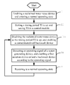
- FIG. 4 is a high-level flowchart diagram illustrating a method for cleaning of a reclaimed water reuse device according to one embodiment of the invention.
- FIG. 5 is a detailed flowchart diagram illustrating a method for cleaning of a reclaimed water reuse device according to one embodiment of the invention.
- a reclaimed water reuse device of the invention comprises a biological reaction tank 1 , a membrane module 2 , a water pool 3 , a membrane filtering pool 4 , a control module 6 , an inlet-drainage device 11 , a clean water supply device 21 , an outlet device 31 , a first aeration device 22 , a second aeration device 12 , a backwash device 23 , and a contaminated-soil backflow device 41 .
- the membrane module 2 is disposed in the membrane filtering pool 4 .
- a separating plate 5 is disposed in the biological reaction tank 1 , and separates the membrane filtering pool 4 from the biological reaction tank 1 .
- Water in the biological reaction tank 1 overflows a top of the separating plate 5 and pours into the membrane filtering pool 4 .
- the ratio between the volume of the biological reaction tank 1 and that of the membrane filtering pool 4 is between 1:1 and 10:1, and more particularly, the ratio is 3:1.
- a groove 51 is disposed at the top of the separating plate 5 .
- the groove 51 is tooth-shaped.
- the inlet-drainage device 11 comprises an inlet pipe 111 , a drainage pipe 112 , and a plurality of electromagnetic valves M 0 and M 1 .
- the electromagnetic valve M 0 is disposed in the inlet pipe 111
- the electromagnetic valve M 1 is disposed in the drainage pipe 112 .
- the outlet device 31 drains water from the water pool 3 .
- the outlet device 31 comprises an outlet pipe 311 , a clean water pump 312 , and an electromagnetic valve M 9 .
- the clean water pump 312 and the electromagnetic valve M 9 are attached to the outlet pipe 311 .
- the clean water supply device 21 comprises a clean water supply pipe 211 , a self-priming pump 212 , an electromagnetic valve M 8 , a manual valve H 8 , and a pressure gauge P.
- the clean water supply pipe 211 connects the water pool 3 to the membrane module 2 .
- the self-priming pump 212 , the electromagnetic valve M 8 , the manual valve H 8 , and the pressure gauge P are connected to the clean water supply pipe 211 and disposed between the membrane module 2 and the water pool 3 .
- the pressure gauge P detects self-priming pressure of the self-priming pump 212 , and transfers the pressure signal to the control module 6 .
- the first aeration device 22 aerates the membrane module 2 , and comprises a first aeration pipe 221 , an electromagnetic valve M 5 and a manual valve H 5 .
- the electromagnetic valve M 5 and the manual valve H 5 are connected to the first aeration pipe 221 .
- the first aeration pipe 221 extends to the bottom of the membrane module 2 .
- the second aeration device 12 aerates the biological reaction tank 1 , and comprises a second aeration pipe 121 , an electromagnetic valve M 3 and a manual valve H 3 .
- the electromagnetic valve M 3 and the manual valve H 3 are connected to the second aeration pipe 121 .
- the second aeration pipe 121 extends to the bottom of the biological reaction tank 1 .
- the aeration pipe 221 and the second aeration pipe 121 have a common entrance.
- the backwash device 23 washes back the membrane filtering pool 4 and connects the outlet device 31 to the membrane module 2 .
- the backwash device 23 comprises a backwash pipe 231 , a first backwash supporting pipe 232 , a second backwash supporting pipe 233 , electromagnetic valves M 6 and M 7 , and a manual valve H 6 .
- the backwash pipe 231 is connected to the outlet pipe 311 , and the other end of the backwash pipe 231 is a common end of the first backwash supporting pipe 232 and the second backwash supporting pipe 233 .
- the first backwash supporting pipe 232 is, at its other end, disposed in the membrane filtering pool 4 .
- the second backwash supporting pipe 233 and the clean water supply pipe 211 are connected to the membrane module 2
- the electromagnetic valve M 6 is connected to the first backwash supporting pipe 232 , and the electromagnetic valve M 7 is connected to the second backwash supporting pipe 233 .
- the contaminated-soil backflow device 41 is disposed in the membrane filtering pool 4 , and is connected to the inlet-drainage device 11 and the biological reaction tank 1 .
- the contaminated-soil backflow device 41 comprises a backflow pipe 411 , a first backflow supporting pipe 412 , a second backflow supporting pipe 413 , a backflow pump 414 , and electromagnetic valves M 2 and M 4 .
- the backflow pump 414 is disposed at the bottom of the membrane filtering pool 4 , and connected to one end of the backflow pipe 411 .
- the other end of the backflow pipe 411 is a common end of the first backflow supporting pipe 412 and the second backflow supporting pipe 413 .
- the first backflow supporting pipe 412 terminates at the top of the biological reaction tank 1
- the second backflow supporting pipe 413 is connected to the outlet pipe 112 .
- the electromagnetic valve M 4 is connected to the first backflow supporting pipe 412 , and the electromagnetic valve M 2 is connected to the second backflow supporting pipe 413 .
- the control module 6 controls operation of the inlet-drainage device 11 , the clean water supply device 21 , the outlet device 31 , the first aeration device 22 , the backwash device 23 , the contaminated-soil backflow device 41 , and the clean water supply device 21 according to preset data and/or signal received from the clean water supply device 21 .
- the preset data comprises a timing period T 0 , a delay time T 1 , a pressure threshold F 1 , a frequency threshold f 1 , and so on.
- the operating signal of the clean water supply device 21 comprises a pressure signal of the pressure gauge P, etc. Based on the pressure signal, the control module 6 detects the operating state of the membrane module 2 , and correspondingly performs physical or chemical backwash of the membrane module 2 .
- control module 6 directly controls operating states of the electromagnetic valves M 0 . . . M 9 , the self-priming pump 212 , the clean water pump 312 , and the backflow pump 414 .
- the backflow pump 414 , the self-priming pump 212 , the clean water pump 312 , and the electromagnetic valves M 4 , M 3 , M 5 , M 8 and M 9 are enabled; the other valves are disabled.
- Manual valves H 3 , H 5 and H 6 may be manually adjusted to change gas flux and water flux.
- contaminated water flows in via the inlet pipe 111 , after biological processing and being filtered by the membrane module 2 in the membrane filtering pool 4 , clean water is generated.
- a method for cleaning a reclaimed water reuse device comprises the following steps:
- a detailed method for cleaning a reclaimed water reuse device comprises the following steps:
- the above steps 4-7 alternately enable contaminated-soil backflow and aeration.
- the above steps 10-14 implement combination of the physical backwash and the chemical backwash.
- the membrane module 2 is not required to be taken out of the membrane filtering pool 4 for cleaning. All of this contributes to a good cleaning efficiency.
- a detailed process of the physical backwash is as follows: the control module 6 enables the electromagnetic valves M 5 and M 7 and the clean water pump 312 , the clean water pump 312 pours filtered water into a membrane tube and a membrane hole in the membrane module 2 , so as to perform backwash thereon. Meanwhile, blowing aeration is performed at the bottom of the membrane module 2 , and contaminant deposited on an upper surface of the membrane module 2 is cleaned. The entire process lasts for 2-10 minutes.
- a detailed process of the chemical backwash is as follows: cleaning chemical agent such as acid, alkali, oxidant (sodium hypochlorite) and so on is added to the water pool 3 , and let the biological reaction tank 1 and the membrane filtering pool 4 stands for 5-15 minutes. In this embodiment, the soaking time is 10 minutes.
- the control module 6 enables the electromagnetic valve M 1 to drain clean water from the upper portion of the biological reaction tank 1 . And then disables the electromagnetic valve M 1 .
- the control module 6 enables the contaminated-soil backflow pump 414 and the electromagnetic valve M 4 , so that active contaminated soil in the membrane filtering pool 4 flows back to the biological reaction tank 1 .
- the control module 6 disables the electromagnetic valve M 4 and enables the electromagnetic valve M 2 after the backflow is completed, so as to discharge clean water in the upper portion of the membrane filtering pool 4 to outside via the contaminated-soil backflow pump 414 .
- the control module 6 disables the contaminated-soil backflow pump 414 after the membrane filtering pool 4 is evacuated.
- the control module 6 enables the clean water pump 312 and the electromagnetic valve M 6 , and allows the cleaning chemical agent to flow into the membrane filtering pool 4 , so as to immerse the membrane module 2 .
- the control module 6 disables the electromagnetic valve M 6 after the cleaning chemical agent immerses the membrane module 2 , enables the electromagnetic valves M 5 and M 7 , and performs chemical backwash on the membrane module 2 . Meanwhile, a membrane surface is scrubbed via aeration.
- the control module 6 disables the electromagnetic valves M 5 and M 7 and the clean water pump 312 , enables the contaminated-soil backflow pump 414 and the electromagnetic valve M 2 , so as to evacuate the cleaning chemical agent in the membrane filtering pool 4 , and then disables the contaminated-soil backflow pump 414 and the electromagnetic valve M 2 .
Landscapes
- Engineering & Computer Science (AREA)
- Water Supply & Treatment (AREA)
- Chemical & Material Sciences (AREA)
- Chemical Kinetics & Catalysis (AREA)
- Life Sciences & Earth Sciences (AREA)
- Biodiversity & Conservation Biology (AREA)
- Microbiology (AREA)
- Hydrology & Water Resources (AREA)
- Environmental & Geological Engineering (AREA)
- Organic Chemistry (AREA)
- Separation Using Semi-Permeable Membranes (AREA)
- Activated Sludge Processes (AREA)
Abstract
Description
-
- i. The reclaimed water reuse device is enabled, and enters a normal operating state;
- ii. A timing period T0 is set, and saved in the
control module 6; - iii. As the timing period T0 is up, the reclaimed water reuse device is disabled; after a delay time T1, the
control module 6 enables the contaminated-soil backflow device 41, so that contaminated soil deposited at the bottom of themembrane filtering pool 4 flows back to a front portion of thebiological reaction tank 1; - iv. The
control module 6 detects an operating signal of the cleanwater supply device 21, and enables thefirst aeration device 22 or/and thebackwash device 23 according to the operating signal, so as to perform physical or chemical backwash of themembrane module 2; and - v. After the backwash is completed, the reclaimed water reuse device restores to a normal operating state under the control of the
control module 6, and the process returns to step iii.
-
- 1. The reclaimed water reuse device is enabled, and enters a normal operating state;
- 2. A timing period T0 is set, and saved in the
control module 6; - 3. The
control module 6 detects whether the timing period is up, if the timing period is not up, the process proceeds to step 4, otherwise the process proceeds to step 9; - 4. If the timing period is up, the
control module 6 detects whether contaminated-soil backflow is enabled. In this embodiment, thecontrol module 6 detects whether contaminated-soil backflow is enabled by checking the signal from thebackwash pump 414, or an operating history saved in thecontrol module 6. If the contaminated-soil backflow is enabled, the process proceeds to step 5, otherwise the process proceeds to step 6; - 5. After a deposit time T1, the
control module 6 stops the contaminated-soil backflow and starts aeration. In this embodiment, thecontrol module 6 switches on the electromagnetic valve M5 in thefirst aeration device 22 and the electromagnetic valve M3 in thesecond aeration device 12, so that gas is led to the bottom of themembrane module 2 and thebiological reaction tank 1 via thefirst aeration pipe 221 and thesecond aeration pipe 121, respectively; - 6. The
control module 6 detects whether aeration is enabled. In this embodiment, thecontrol module 6 detects whether aeration is enabled by checking states of the electromagnetic valve M5 and the electromagnetic valve M3. If the aeration is enabled, the process proceeds to step 7, otherwise the process proceeds to step 8; - 7. The
control module 6 stops the aeration, and enables the contaminated-soil backflow after the deposit time T1; - 8. The
control module 6 enables the contaminated-soil backflow after the deposit time T1; - 9. The
control module 6 sets a pressure threshold F1 and a frequency threshold f1. In this embodiment, the pressure threshold F1 is between +0.04 and −0.04 MPa with respect to the standard pressure of 760 mmHg (101,325 Pa). - 10. The
control module 6 receives a pressure signal from the pressure gauge P, the pressure gauge indicating self-priming pressure of the self-primingpump 212; - 11. The
control module 6 detects whether the self-priming pressure is greater than the pressure threshold F1. If the self-priming pressure is greater than the pressure threshold F1, the process proceeds to step 12, otherwise the process returns to step 3; - 12. The
control module 6 detects whether a frequency at which the self-priming pressure of the self-primingpump 212 exceeds the pressure threshold F1 is greater than the frequency threshold f1. If the frequency at which the self-priming pressure of the self-primingpump 212 exceeds the pressure threshold F1 is greater than the frequency threshold f1, the process proceeds to step 13, otherwise the process proceeds to step 14. In this embodiment, the frequency at which the self-priming pressure of the self-primingpump 212 exceeds the pressure threshold F1 is equal to 1/(the amount of time the self-priming pressure of the self-primingpump 212 exceeds the pressure threshold F1 during this time interval−the amount of time the self-priming pressure of the self-primingpump 212 exceeds the pressure threshold F1 during the immediately preceding time interval); - 13. the
control module 6 exits the normal operating state, and performs chemical backwash on themembrane module 2; - 14. The
control module 6 exits the normal operating state, and enables thefirst aeration device 22 and thebackwash device 23, so as to perform physical backwash on themembrane module 2; and - 15. Under the control of the
control module 6, the reclaimed water reuse device is restored to its normal operating state, and then the process returns to step 3.
Claims (14)
Priority Applications (1)
| Application Number | Priority Date | Filing Date | Title |
|---|---|---|---|
| US12/429,387 US7833420B2 (en) | 2006-09-21 | 2009-04-24 | Method for cleaning reclaimed water reuse device |
Applications Claiming Priority (5)
| Application Number | Priority Date | Filing Date | Title |
|---|---|---|---|
| CN200610062687 | 2006-09-21 | ||
| CN200610062687.7 | 2006-09-21 | ||
| CNB2006100626877A CN100453478C (en) | 2006-09-21 | 2006-09-21 | Intelligent reclaimed water recycling equipment |
| US11/858,921 US7556730B2 (en) | 2006-09-21 | 2007-09-21 | Reclaimed water reuse device |
| US12/429,387 US7833420B2 (en) | 2006-09-21 | 2009-04-24 | Method for cleaning reclaimed water reuse device |
Related Parent Applications (1)
| Application Number | Title | Priority Date | Filing Date |
|---|---|---|---|
| US11/858,921 Continuation US7556730B2 (en) | 2006-09-21 | 2007-09-21 | Reclaimed water reuse device |
Publications (2)
| Publication Number | Publication Date |
|---|---|
| US20090206036A1 US20090206036A1 (en) | 2009-08-20 |
| US7833420B2 true US7833420B2 (en) | 2010-11-16 |
Family
ID=37777631
Family Applications (2)
| Application Number | Title | Priority Date | Filing Date |
|---|---|---|---|
| US11/858,921 Active US7556730B2 (en) | 2006-09-21 | 2007-09-21 | Reclaimed water reuse device |
| US12/429,387 Active 2027-10-05 US7833420B2 (en) | 2006-09-21 | 2009-04-24 | Method for cleaning reclaimed water reuse device |
Family Applications Before (1)
| Application Number | Title | Priority Date | Filing Date |
|---|---|---|---|
| US11/858,921 Active US7556730B2 (en) | 2006-09-21 | 2007-09-21 | Reclaimed water reuse device |
Country Status (3)
| Country | Link |
|---|---|
| US (2) | US7556730B2 (en) |
| CN (1) | CN100453478C (en) |
| FR (2) | FR2906802B1 (en) |
Families Citing this family (11)
| Publication number | Priority date | Publication date | Assignee | Title |
|---|---|---|---|---|
| US9238586B2 (en) * | 2008-11-20 | 2016-01-19 | Alion Science & Technology | Filter cleaning method |
| DE102008054727A1 (en) * | 2008-12-16 | 2010-06-17 | Robert Bosch Gmbh | Water treatment plant and method and computer program for operating a water treatment plant |
| CN104056554B (en) * | 2014-01-20 | 2016-05-18 | 绿能(杭州)企业管理有限公司 | A kind of MBR on-line cleaning method |
| US20160096146A1 (en) * | 2014-10-07 | 2016-04-07 | Derek Oxford | Microfiltration systems for cleaning waste water |
| CN106587331A (en) * | 2015-10-20 | 2017-04-26 | 江苏清泉环保设备有限公司 | Novel flat plate MBR treatment device for treating steel rolling waste water |
| CN109071291B (en) * | 2016-04-28 | 2021-09-07 | 东丽株式会社 | Wastewater treatment method using membrane separation activated sludge method |
| CN108117150A (en) * | 2018-01-22 | 2018-06-05 | 浙江滨盛环境科技有限公司 | A kind of novel plug formula integrated sewage treatment device |
| CN110871035A (en) * | 2018-08-30 | 2020-03-10 | 中国石油化工股份有限公司 | MBR plate-type membrane cleaning system and application |
| CN109179869A (en) * | 2018-09-19 | 2019-01-11 | 梁善武 | The sewage treatment process and autocontrol operation method of no additional carbon removal total nitrogen |
| CN114195257A (en) * | 2021-11-29 | 2022-03-18 | 广东景天环境科技股份有限公司 | MBR (membrane bioreactor) water treatment equipment and water treatment method |
| CN114870636B (en) * | 2022-06-01 | 2023-02-28 | 北京新城禹潞环保科技有限责任公司 | Method for cleaning membrane module device |
Citations (2)
| Publication number | Priority date | Publication date | Assignee | Title |
|---|---|---|---|---|
| US20070138092A1 (en) * | 2005-12-20 | 2007-06-21 | Smith Paul J L | Method and system for controlling duration of a backwash cycle of a filtration system |
| US20070138096A1 (en) * | 2004-11-05 | 2007-06-21 | Tarr Ronald S | Systems and methods for controlling contaminate levels of processed water and maintaining membranes |
Family Cites Families (5)
| Publication number | Priority date | Publication date | Assignee | Title |
|---|---|---|---|---|
| JPH11128699A (en) * | 1997-10-29 | 1999-05-18 | Mitsubishi Rayon Co Ltd | Filtration method by separation membrane |
| CN1156410C (en) * | 2000-12-15 | 2004-07-07 | 中国科学院生态环境研究中心 | Split membrane bioreactor |
| CN2530940Y (en) * | 2002-02-28 | 2003-01-15 | 杨振刚 | Gas-water backflush device of membrane for membrane bioreactor |
| JP4088630B2 (en) * | 2005-02-28 | 2008-05-21 | シャープ株式会社 | Wastewater treatment equipment |
| US7713410B2 (en) * | 2005-12-20 | 2010-05-11 | Sharp Kabuhsiki Kaisha | Wastewater treatment apparatus |
-
2006
- 2006-09-21 CN CNB2006100626877A patent/CN100453478C/en active Active
-
2007
- 2007-09-19 FR FR0706578A patent/FR2906802B1/en active Active
- 2007-09-21 US US11/858,921 patent/US7556730B2/en active Active
-
2009
- 2009-04-24 US US12/429,387 patent/US7833420B2/en active Active
-
2010
- 2010-09-06 FR FR1057046A patent/FR2945805B1/en active Active
Patent Citations (2)
| Publication number | Priority date | Publication date | Assignee | Title |
|---|---|---|---|---|
| US20070138096A1 (en) * | 2004-11-05 | 2007-06-21 | Tarr Ronald S | Systems and methods for controlling contaminate levels of processed water and maintaining membranes |
| US20070138092A1 (en) * | 2005-12-20 | 2007-06-21 | Smith Paul J L | Method and system for controlling duration of a backwash cycle of a filtration system |
Also Published As
| Publication number | Publication date |
|---|---|
| CN1919750A (en) | 2007-02-28 |
| US20090206036A1 (en) | 2009-08-20 |
| CN100453478C (en) | 2009-01-21 |
| FR2906802B1 (en) | 2013-01-11 |
| US20080073285A1 (en) | 2008-03-27 |
| FR2945805A1 (en) | 2010-11-26 |
| US7556730B2 (en) | 2009-07-07 |
| FR2906802A1 (en) | 2008-04-11 |
| FR2945805B1 (en) | 2015-05-29 |
Similar Documents
| Publication | Publication Date | Title |
|---|---|---|
| US7833420B2 (en) | Method for cleaning reclaimed water reuse device | |
| US7276171B2 (en) | Method for cleaning separation membrane | |
| CN103752175A (en) | Immersed type on-line cleaning method and device for slab ceramic membrane | |
| JP2945894B2 (en) | How to remove cleaning chemicals | |
| CN106542631B (en) | A kind of system and method for chemical cleaning ceramic membrane | |
| CN107349793B (en) | A system and method for off-line chemical cleaning of MBR membrane unit | |
| CN111032578A (en) | Water treatment membrane cleaning device and cleaning method | |
| JP5245216B2 (en) | Hollow fiber membrane water treatment method and water treatment apparatus | |
| KR101926857B1 (en) | Automatic cleaning system of separation membrane and method using the same | |
| CN111874996A (en) | Tubular microfiltration membrane wastewater treatment process | |
| JP5423184B2 (en) | Filtration membrane module cleaning method and cleaning apparatus | |
| CN213433878U (en) | A three-stage cleaning automatic operation equipment for ultrafiltration membrane for dry and wet landfill leachate | |
| JP2002126468A (en) | Membrane module cleaning method and membrane filtration device | |
| CN109331664B (en) | Ultrafiltration membrane flushing device and method | |
| JP4385483B2 (en) | Wastewater treatment method | |
| JP2000210540A (en) | Membrane filter apparatus | |
| JPH0737322U (en) | Membrane separation device | |
| JP2016137469A (en) | Method and device for cleaning air diffusion pipe, and activated sludge treatment method and activated sludge treatment system | |
| CN112573623A (en) | Continuous dynamic membrane system operation device and working method thereof | |
| CN221334247U (en) | Chromatographic resin chemical regeneration device and regeneration system | |
| JPH0999226A (en) | How to clean the membrane | |
| CN216837416U (en) | Integrated equipment is got rid of to heavy metal | |
| JPH11347377A (en) | Solid-liquid separation device and its cleaning method | |
| JP3858562B2 (en) | Membrane immersion type solid-liquid separator | |
| JPH09239247A (en) | Immersion type membrane separation apparatus and membrane washing method therein |
Legal Events
| Date | Code | Title | Description |
|---|---|---|---|
| AS | Assignment |
Owner name: SHENZHEN JDL ENVIRONMENTAL PROTECTION LTD., CHINA Free format text: ASSIGNMENT OF ASSIGNORS INTEREST;ASSIGNORS:LIAO, ZHIMIN;LI, RONG;WU, JIJUN;AND OTHERS;REEL/FRAME:022593/0015;SIGNING DATES FROM 20090401 TO 20090408 Owner name: SHENZHEN JDL ENVIRONMENTAL PROTECTION LTD., CHINA Free format text: ASSIGNMENT OF ASSIGNORS INTEREST;ASSIGNORS:LIAO, ZHIMIN;LI, RONG;WU, JIJUN;AND OTHERS;SIGNING DATES FROM 20090401 TO 20090408;REEL/FRAME:022593/0015 |
|
| STCF | Information on status: patent grant |
Free format text: PATENTED CASE |
|
| AS | Assignment |
Owner name: JIANGXI JDL ENVIRONMENTAL PROTECTION RESEARCH LTD. Free format text: ASSIGNMENT OF ASSIGNORS INTEREST;ASSIGNOR:SHENZHEN JDL ENVIRONMENTAL PROTECTION LTD.;REEL/FRAME:028192/0239 Effective date: 20120511 |
|
| AS | Assignment |
Owner name: JIANGXI JDL ENVIRONMENTAL PROTECTION CO., LTD., CH Free format text: ASSIGNMENT OF ASSIGNORS INTEREST;ASSIGNOR:JIANGXI JDL ENVIRONMENTAL PROTECTION RESEARCH LTD.;REEL/FRAME:029389/0616 Effective date: 20121030 |
|
| FPAY | Fee payment |
Year of fee payment: 4 |
|
| MAFP | Maintenance fee payment |
Free format text: PAYMENT OF MAINTENANCE FEE, 8TH YR, SMALL ENTITY (ORIGINAL EVENT CODE: M2552) Year of fee payment: 8 |
|
| FEPP | Fee payment procedure |
Free format text: ENTITY STATUS SET TO UNDISCOUNTED (ORIGINAL EVENT CODE: BIG.); ENTITY STATUS OF PATENT OWNER: LARGE ENTITY |
|
| MAFP | Maintenance fee payment |
Free format text: PAYMENT OF MAINTENANCE FEE, 12TH YEAR, LARGE ENTITY (ORIGINAL EVENT CODE: M1553); ENTITY STATUS OF PATENT OWNER: LARGE ENTITY Year of fee payment: 12 |
|
| AS | Assignment |
Owner name: JDL GLOBAL ENVIRONMENTAL PROTECTION, INC., NEW YORK Free format text: ASSIGNMENT OF ASSIGNORS INTEREST;ASSIGNOR:JIANGXI JDL ENVIRONMENTAL PROTECTION CO., LTD.;REEL/FRAME:065517/0470 Effective date: 20231106 |