US782897A - Boiler-tube cleaner and actuating means therefor. - Google Patents
Boiler-tube cleaner and actuating means therefor. Download PDFInfo
- Publication number
- US782897A US782897A US14137503A US1903141375A US782897A US 782897 A US782897 A US 782897A US 14137503 A US14137503 A US 14137503A US 1903141375 A US1903141375 A US 1903141375A US 782897 A US782897 A US 782897A
- Authority
- US
- United States
- Prior art keywords
- boiler
- tube
- head
- shaft
- engine
- Prior art date
- Legal status (The legal status is an assumption and is not a legal conclusion. Google has not performed a legal analysis and makes no representation as to the accuracy of the status listed.)
- Expired - Lifetime
Links
- 238000004140 cleaning Methods 0.000 description 7
- 238000010276 construction Methods 0.000 description 6
- XLYOFNOQVPJJNP-UHFFFAOYSA-N water Substances O XLYOFNOQVPJJNP-UHFFFAOYSA-N 0.000 description 5
- 239000000463 material Substances 0.000 description 4
- 230000001464 adherent effect Effects 0.000 description 2
- 206010022000 influenza Diseases 0.000 description 2
- 229910000897 Babbitt (metal) Inorganic materials 0.000 description 1
- 208000027418 Wounds and injury Diseases 0.000 description 1
- 230000005540 biological transmission Effects 0.000 description 1
- 230000006378 damage Effects 0.000 description 1
- 208000014674 injury Diseases 0.000 description 1
- 238000009434 installation Methods 0.000 description 1
- 238000009877 rendering Methods 0.000 description 1
- 239000012858 resilient material Substances 0.000 description 1
- 230000013707 sensory perception of sound Effects 0.000 description 1
- 238000005406 washing Methods 0.000 description 1
Images


Classifications
-
- B—PERFORMING OPERATIONS; TRANSPORTING
- B08—CLEANING
- B08B—CLEANING IN GENERAL; PREVENTION OF FOULING IN GENERAL
- B08B9/00—Cleaning hollow articles by methods or apparatus specially adapted thereto
- B08B9/02—Cleaning pipes or tubes or systems of pipes or tubes
- B08B9/027—Cleaning the internal surfaces; Removal of blockages
- B08B9/04—Cleaning the internal surfaces; Removal of blockages using cleaning devices introduced into and moved along the pipes
- B08B9/043—Cleaning the internal surfaces; Removal of blockages using cleaning devices introduced into and moved along the pipes moved by externally powered mechanical linkage, e.g. pushed or drawn through the pipes
- B08B9/045—Cleaning the internal surfaces; Removal of blockages using cleaning devices introduced into and moved along the pipes moved by externally powered mechanical linkage, e.g. pushed or drawn through the pipes the cleaning devices being rotated while moved, e.g. flexible rotating shaft or "snake"
Definitions
- ma -m1 BOILER TUBE 0105mm AND lacamma MBANEi THEREFOR APPLICATION PILED JAN. 31, 1903.
- This invention relates more particularly to a boiler tube or flue cleaner designed to be driven at a high rate of speed by an engine or motor and having its parts so constructed as to cut and scrape adherent material from the boiler tube or flue and also to scour the lines during the operation.
- the object of this invention is to provide a construction whereby an auxiliary engine or motor adjustably supported upon a knockdown frame is rigidly secured at the boiler end when it is desired to clean the boiler and is adapted to be removed therefrom when the cleaning operation is complete.
- Figure 1 is a front perspective view of a device embodying my in vention,showing the same in operative engagement with the boiler-head.
- Fig. 2 is a reduced vertical longitudinal section ofthe same, showing one of the boiler-fines in longitudinal sectherefrom and thoroughly Application filed January 31, 1903. Serial No. 141,375.
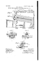
- Fig. 3 is an enlarged detail of the adjusting-clamps for the motor-supporting bar.
- Fig. 4 is a section taken on line 4c4tof Fig. 3.
- Fig. 5 is an enlarged fragmentary longitudinal section of one of the boiler flues or tubes,
- Fig. 6 is an enlargedside elevation, partly broken away to show the gearing of the motor embodied in my invention.
- Fig. 7 is an enlarged side elevation of the cutter or cleaner head embodied in my invention and illustrates the means of securing the same upon the tubular shaft.
- Fig. 8 is a section taken on line 8 8 of Fig. 7.
- Fig. 9 is a section taken on line 9 9 of Fig. 7.
- Fig. 10 is a perspective View similar to Fig. 1 and illustrates a different attachment with the boiler.
- a supporting-frame is provided for the actuating means for the cleaner, which is rigidly but adjustably secured upon brackets which engage on the outer or front end of the boiler.
- a rotary steam-engine of any desiredor preferred type and which is geared to drive the operating-shaft and the cutter-head on the inner end thereof at a high rate of speed.
- said frame comprises two cylindric rods or bars A and A. which are held parallel with the head of the water-tube boiler X by means of the bracketarms a a, which, as shown, are bent laterally and outwardly from the boiler ends, carrying said rods or bars out of alinement with the tubes.
- Bracket-arms are each provided at their outer ends with transverse sleeves, through which the rods A and A passv and on which are provided set screws adapted to firmly grip the rods or bars in position when engaged therein.
- the inner ends of said bracket-arms are shaped to provide an enlarged flat face a at a right angle with the arm and adapted to bear against and close the opening in the boiler in alinement with one of the tubes.
- a pad a of rubber or other resilient material, which acts to absorb vibration, is secured thereon by means of a bolt (0*, which also passes through the head of a flanged retaining capor washer a, which, as shown, fits closely in the aperture in the head and serves to hold the bracket-arm in adjustment.
- a bolt or rod rt passes through the port of the bracket-arm, resilient pad, and washer and is provided on the outer end with a nut or other adjusting means and on the inner with a transverse bar engaged centrally thereon and adapted to engage on the inner side of the head between the same and the header and to resist outward strain thereon, thereby rigidly holding the bracket-arms and the rods supported therein in adjusted position.
- a vertically-adjustable clip comprising a bearingblock B, having a bore therethrough of a size to receive the rods A or A and a set-screw 7) in position to positively engage the rods when secured therein.
- a cap 5' is rigidly secured on said bearing-block by means of bolts 6
- a cylindric bearing for the engin e-supporting bar or shaft C is thus afforded.
- Said shaft is tubular and rectangular in crosssection and in said bearing is fitted closely in the slit sleeve C, which, as shown, is rotative in the bore of the bearing-block for purposes of adjustment and is provided with an angular aperture therethrough adapted to receive and fit closely to the shaft (1.
- the sleeve 0 is slightly larger than its seat, so that when the nuts on the bolts 7)2 are set up the shaft 0 is rigidly held from lateral movement, while the set-screws 6 hold the ends of said shaft in their vertical adjustment.
- a collar B is engaged on each rod A or A below the bearing-block and held in position by setscrews and acts to support the motor-shaft C in adjusted position.
- the rotary engine Slidably secured upon the shaft (1 is the rotary engine, indicated as a whole by D and comprising the engine proper, which may be of any desired type and is contained in a casing (Z, and the rearwardly-directed longitudinal shaft (Z, which, as shown, is provided at its outer end with a gear (Z At its rear end the casing (Z is provided with the socket or sleeve d, integral with the rear head of the casing and adapted to slide on the shaft 0 and to be rigidly secured thereon by means of a setscrew or in other desired manner.
- a bracket integral with the rear head of the casing (Z extends upwardly and forms at its top an integral sleeve (Z provided with an internal bushingof bearing metal or other suitable material (Z and within which is fitted the elongated hub (Z of the gear-wheel (Z which meshes with the gear-wheel (Z and serves to backgear said engine.
- An angular axial aperture is provided through said hub and geae, which tapers from the boiler-head and is adapted to receive the tubular rectangular shaft E and to permit the ends of the same considerable freedom of movement while slidingfreely through said gear and hub when being forced into or l drawn out of the tube.
- a'metallie casing F is provided around said gears, which serves to protect the operator from injury and to prevent the gears being injured by any foreign bodies engaging between the same.
- the inlet-port Gr of the engine is connected, by means of steam-hose or otherwise, with the steam-pipe g, and a throttle-valve g is provided in said pipe at a convenient point to enable the action of the engine and tool to be controlled by the operator.
- the exhaust-pipe 9 leads from the exhaust-port and connects in a hose-pipe g, which leads to a source of water-supply and is extended into the tube to be cleaned, so that the exhaust-steam constantly siphons water into the tube during the cleaning operation, washing out the scale as fast as cut or broken from the tube.
- the cutter-head employed in the tube is the same as that for which I have executed and filed application for United States Letters Patent of even date herewith and of the same class as shown in my Patent No. 615A27, issued December 6, 1898, and comprises, as shown, a revoluble head H, having recesses in the side thereof and having conical cutters it journaled in said recesses by means which permit the same to be thrown outwardly when the cutter is rotated in one direction and to fall inwardly when the rotation of the cutter is reversed.
- One or more cutters it are also provided in advance of the cutters h, which, however, are held in unvarying relation with the axis of the head, so that as the cutter-head rotates the cutters near the front end of the head begin the operation of cleaning the tube, while the outward movement of the cutters near the rear end of the head causes the same to engage against the adherent material in the inner side of the tube with great force, thereby causing the cutters to rotate oppositely from the rotation of the head.
- TheV-shaped thread on said cutters act to out and pull the refuse material from the tube and force it outwardly, aided by the water siphoned into the tube from the engine, as before described.
- The-head is provided at its rear end with a shank H, angular in cross-section and adapted to fit closely in the end of the shaft E.
- a spring-de'tent or push-pin is provided in said shank, extending transversely thereof, and is adapted when the shank is inserted in the end shaft to spring outwardly and engage in an aperture therein, thereby holding the head from removal therefrom.
- the outer end of said shaft E is provided with a flexible non-rotative handle I, similar to that shown in my United States Letters Patent No. 679,723, issued to me on the 6th day of August, 1901, for boiler-tube cleaner and driving mechanism therefor.
- the operation is as follows: The frame being engaged upon the front end of the boiler by means of the bracket-arms, each of which engages in a tube, as shown, the transverse motor-supporting shaft or bar C is adjusted by means of the bearing-block B to the desired vertical height on the bars A and A and the supporting-sleeves B set up to support the same. The engine is slidably supported on said bar,-permitting the same to be adjusted laterally to the tubes. The pipe connec tions are then made to supply live'steam to the engine, and the rotatable shaft is passed through the gear-wheel (Z7, the cutter-head H secured on its front end, and the flexible handle I secured on its rear end in position to be engaged by the operator.
- a platform or staging J is provided in front of the boiler of a desired height to enable the operator to have convenient access to the mechanism and to operate the device.
- the cutter-head is inserted in the tube, steam is admitted to the engine, and the cutter-head rapidly rotated.
- the revolution of the shaft will approximate eight hundred revolutions per minute, though obviously the rate of revolutions may vary according to the conditions existing in the tube.
- the cutters it on entering the flue start the cutting or cleaning operation, while the cutters 7b are thrown outwardly by the rapid rotation into positive engagement with the inner periphery of the tube, their engagement therewith being suflicient to cut all scale or other refuse from the tube.
- threaded apertures may be provided in the fire-front, as shown in Fig. 10, and bolts K' may be inserted through the bracket foot to engage therein, thereby removing the brackets from before the boiler end and permitting access to every tube without shifting.
- motor or engine may be of any desired construction, and, if preferred, the parts of the supporting-frame may assume various shapes, and many details of construction may be varied without departing from the principles of this invention.
- a device of the class described comprising vertically-disposed frame members adjustable with respect to each other, a plurality of bracket-arms having sleeved outer ends adapted to ad justably engage said frame members, means on the inner ends of said bracketarms adapted to engage theboiler-front, vertically-adjustable hearings on said frame members, a transverse bar adj ustably and rotatively engaged in said bearing, a rotary engine thereon, a longitudinally-movable shaft connected with said engine by means affording a swivel movement and adapted to be inserted in a boiler-tube and means adapted to admit water in said tube.
- a device of the class described comprising a vertically-adjustable supporting-frame adapted to be engaged on a boiler-front, a rotary engine secured thereon by means permitting vertical and lateral adjustment, flexible means for admitting live steam to said engine, means operated by the exhaust-steam acting to siphon water into the tube operated upon, a gear on said engine provided with an angular tapered aperture therethrough, an angular tubular shaft adapted to swi-vel in said aperture, a non-rotative flexible handle on the outer end thereof, a cutter-head on the inner end of said shaft comprising a head having outwardly-movable, indepcndently-rotatable, conical cutters thereon adapted to be thrown outwardly into more positive engagement with the tube by rotation of the shaft and a springdetent acting to lock said head to the shaft.
- a knockdown frame for the purpose specified comprising bracket-arms having the inner ends bent at approximately a right angle therewith, means thereon for engaging each of the same to a boiler-head or the like, sleeves on the outer ends of said bracket-arms, rigid bars positively engaged in said sleeves, a sliding bearing-block on each of said bars, means thereon adapted to rigidly engage the bearing-blocks in adjusted position on said bars, an angular bar ad justably secured thereon, and adapted to adjustably support a motor or the like.
- a bracket-arm for the purpose specified having a foot at approximately right angles therewith and bent laterally near the middle thereof, a clamping-sleeve at the outer end of said bracket-arm, a resilient pad engaged against the foot thereof, a flanged washer adapted to engage in the tube-opening of a boiler-head or the like and removably secured at the foot of the bracket-arm by means of a bolt passing through said foot, resilient pad and washer and a threaded shaft also extending through said parts and a bar pivoted centrally thereon at its inner end and adapted to rigidly engage transversely between the boiler head and header and a nut on the outer end thereof adapted to draw said bar into positive engagement between the line.
Landscapes
- Engineering & Computer Science (AREA)
- Mechanical Engineering (AREA)
- Cleaning By Liquid Or Steam (AREA)
Description
'w. L, ma -m1: BOILER TUBE 0105mm AND lacamma MBANEi THEREFOR APPLICATION PILED JAN. 31, 1903.
4 EHEET$-EHEET 3.
PATENTED FEB. 21, 1905 I w. L. GASADAY. BOILER TUBE CLEANER AND AOTUATING MEANS THEREFOR.
APPLICATION FILED JAN. 31, 1903.
4-SHE E'IS-SHEET 2.
Wf/ZQUQI 'PATENTEB FEB. 21, 1905.
W. L. GASABAK urmmnou FILED J$1q. a1, 1903.
4 SHEETS-SEES! "I.
fiiyazzfa/ BOILER TUBE CLEANER AND AGTU'AT'L'NG MEANS! THEREFOR.
PATENTED FEB 21, 1905.
' W. L. CASADAY. v
BOILER TUBE GLEANER AND AUTUATING MEANS THEREFOR.
APPLIGATION FILED JAL 31. 1903.
Patented February 21, 1905.
PATENT OFFICE.
WILLIAM L. CASADAY, OF SOUTH BEND, INDIANA.
BOILER-TUBE CLEANER AND ACTUATING MEANS THEREFOR.
SPECIFICATION forming part of Letters Patent No. 782,897, dated. February 21, 1905.
To all whom, it may concern:
Be it known thatI, WILLIAM L. CAsAnAY, a citizen of the United States, and a resident of the city of South Bend, county of St. Joseph, and State of Indiana, have invented certain new and useful Improvements in Boiler-Tube Cleaners and Actuating Means Therefor; and I do hereby declare that the following is a full, clear, and exact description of the same, reference being had to the accompanying drawings, and to the letters of reference marked thereon, which form a part of this specification.
This invention relates more particularly to a boiler tube or flue cleaner designed to be driven at a high rate of speed by an engine or motor and having its parts so constructed as to cut and scrape adherent material from the boiler tube or flue and also to scour the lines during the operation.
Heretofore many different constructions have been devised, many of which have been cumbersome to install and difficult to operate and in most of which if power other than manual were used the installation, shafting, and pulleys and other means for power transmission are necessary. This is usually cumbersome and, if stationary, often prooves inconvenient when the device is not in use.
The object of this invention is to provide a construction whereby an auxiliary engine or motor adjustably supported upon a knockdown frame is rigidly secured at the boiler end when it is desired to clean the boiler and is adapted to be removed therefrom when the cleaning operation is complete.
It is also an object of the invention to pro-' vide in connection with the cleaner means for admitting a jet of water into the tube during the cleaning operation, thus aiding to force the scale outwardly clean the tubes.
The invention embraces many novel features; and it consists in the matters hereinafter described,and more fully pointed out and defined in the appended claims.
In the drawings, Figure 1 is a front perspective view of a device embodying my in vention,showing the same in operative engagement with the boiler-head. Fig. 2 is a reduced vertical longitudinal section ofthe same, showing one of the boiler-fines in longitudinal sectherefrom and thoroughly Application filed January 31, 1903. Serial No. 141,375.
tion and illustrating the operation of the device. Fig. 3 is an enlarged detail of the adjusting-clamps for the motor-supporting bar. Fig. 4: is a section taken on line 4c4tof Fig. 3. Fig. 5 is an enlarged fragmentary longitudinal section of one of the boiler flues or tubes,
illustrating the means for securing the device to the boiler-head. Fig. 6 is an enlargedside elevation, partly broken away to show the gearing of the motor embodied in my invention. Fig. 7 is an enlarged side elevation of the cutter or cleaner head embodied in my invention and illustrates the means of securing the same upon the tubular shaft. Fig. 8 is a section taken on line 8 8 of Fig. 7. Fig. 9 is a section taken on line 9 9 of Fig. 7. Fig. 10 is a perspective View similar to Fig. 1 and illustrates a different attachment with the boiler.
In said drawings a supporting-frame is provided for the actuating means for the cleaner, which is rigidly but adjustably secured upon brackets which engage on the outer or front end of the boiler. On said frame is adjustably secured, as shown, a rotary steam-engine of any desiredor preferred type and which is geared to drive the operating-shaft and the cutter-head on the inner end thereof at a high rate of speed. As shown, said frame comprises two cylindric rods or bars A and A. which are held parallel with the head of the water-tube boiler X by means of the bracketarms a a, which, as shown, are bent laterally and outwardly from the boiler ends, carrying said rods or bars out of alinement with the tubes. Said bracket-arms are each provided at their outer ends with transverse sleeves, through which the rods A and A passv and on which are provided set screws adapted to firmly grip the rods or bars in position when engaged therein. The inner ends of said bracket-arms are shaped to provide an enlarged flat face a at a right angle with the arm and adapted to bear against and close the opening in the boiler in alinement with one of the tubes. A pad a of rubber or other resilient material, which acts to absorb vibration, is secured thereon by means of a bolt (0*, which also passes through the head of a flanged retaining capor washer a, which, as shown, fits closely in the aperture in the head and serves to hold the bracket-arm in adjustment. A bolt or rod rt passes through the port of the bracket-arm, resilient pad, and washer and is provided on the outer end with a nut or other adjusting means and on the inner with a transverse bar engaged centrally thereon and adapted to engage on the inner side of the head between the same and the header and to resist outward strain thereon, thereby rigidly holding the bracket-arms and the rods supported therein in adjusted position.
Slidably secured on each of the rods or bars A between the bracket-arms is provided a vertically-adjustable clip, comprising a bearingblock B, having a bore therethrough of a size to receive the rods A or A and a set-screw 7) in position to positively engage the rods when secured therein. A cap 5' is rigidly secured on said bearing-block by means of bolts 6 A cylindric bearing for the engin e-supporting bar or shaft C is thus afforded. Said shaft, as shown, is tubular and rectangular in crosssection and in said bearing is fitted closely in the slit sleeve C, which, as shown, is rotative in the bore of the bearing-block for purposes of adjustment and is provided with an angular aperture therethrough adapted to receive and fit closely to the shaft (1. The sleeve 0 is slightly larger than its seat, so that when the nuts on the bolts 7)2 are set up the shaft 0 is rigidly held from lateral movement, while the set-screws 6 hold the ends of said shaft in their vertical adjustment. As shown also a collar B is engaged on each rod A or A below the bearing-block and held in position by setscrews and acts to support the motor-shaft C in adjusted position.
Slidably secured upon the shaft (1 is the rotary engine, indicated as a whole by D and comprising the engine proper, which may be of any desired type and is contained in a casing (Z, and the rearwardly-directed longitudinal shaft (Z, which, as shown, is provided at its outer end with a gear (Z At its rear end the casing (Z is provided with the socket or sleeve d, integral with the rear head of the casing and adapted to slide on the shaft 0 and to be rigidly secured thereon by means of a setscrew or in other desired manner. A bracket integral with the rear head of the casing (Z extends upwardly and forms at its top an integral sleeve (Z provided with an internal bushingof bearing metal or other suitable material (Z and within which is fitted the elongated hub (Z of the gear-wheel (Z which meshes with the gear-wheel (Z and serves to backgear said engine. An angular axial aperture is provided through said hub and geae, which tapers from the boiler-head and is adapted to receive the tubular rectangular shaft E and to permit the ends of the same considerable freedom of movement while slidingfreely through said gear and hub when being forced into or l drawn out of the tube. As shown, a'metallie casing F is provided around said gears, which serves to protect the operator from injury and to prevent the gears being injured by any foreign bodies engaging between the same.
The inlet-port Gr of the engine is connected, by means of steam-hose or otherwise, with the steam-pipe g, and a throttle-valve g is provided in said pipe at a convenient point to enable the action of the engine and tool to be controlled by the operator. The exhaust-pipe 9 leads from the exhaust-port and connects in a hose-pipe g, which leads to a source of water-supply and is extended into the tube to be cleaned, so that the exhaust-steam constantly siphons water into the tube during the cleaning operation, washing out the scale as fast as cut or broken from the tube.
The cutter-head employed in the tube is the same as that for which I have executed and filed application for United States Letters Patent of even date herewith and of the same class as shown in my Patent No. 615A27, issued December 6, 1898, and comprises, as shown, a revoluble head H, having recesses in the side thereof and having conical cutters it journaled in said recesses by means which permit the same to be thrown outwardly when the cutter is rotated in one direction and to fall inwardly when the rotation of the cutter is reversed. One or more cutters it are also provided in advance of the cutters h, which, however, are held in unvarying relation with the axis of the head, so that as the cutter-head rotates the cutters near the front end of the head begin the operation of cleaning the tube, while the outward movement of the cutters near the rear end of the head causes the same to engage against the adherent material in the inner side of the tube with great force, thereby causing the cutters to rotate oppositely from the rotation of the head. TheV-shaped thread on said cutters act to out and pull the refuse material from the tube and force it outwardly, aided by the water siphoned into the tube from the engine, as before described.
The-head is provided at its rear end with a shank H, angular in cross-section and adapted to fit closely in the end of the shaft E. As shown, a spring-de'tent or push-pin is provided in said shank, extending transversely thereof, and is adapted when the shank is inserted in the end shaft to spring outwardly and engage in an aperture therein, thereby holding the head from removal therefrom.
, The outer end of said shaft E is provided with a flexible non-rotative handle I, similar to that shown in my United States Letters Patent No. 679,723, issued to me on the 6th day of August, 1901, for boiler-tube cleaner and driving mechanism therefor.
The operation is as follows: The frame being engaged upon the front end of the boiler by means of the bracket-arms, each of which engages in a tube, as shown, the transverse motor-supporting shaft or bar C is adjusted by means of the bearing-block B to the desired vertical height on the bars A and A and the supporting-sleeves B set up to support the same. The engine is slidably supported on said bar,-permitting the same to be adjusted laterally to the tubes. The pipe connec tions are then made to supply live'steam to the engine, and the rotatable shaft is passed through the gear-wheel (Z7, the cutter-head H secured on its front end, and the flexible handle I secured on its rear end in position to be engaged by the operator. Conveniently a platform or staging J is provided in front of the boiler of a desired height to enable the operator to have convenient access to the mechanism and to operate the device. The cutter-head is inserted in the tube, steam is admitted to the engine, and the cutter-head rapidly rotated. Usually the revolution of the shaft will approximate eight hundred revolutions per minute, though obviously the rate of revolutions may vary according to the conditions existing in the tube. The cutters it on entering the flue start the cutting or cleaning operation, while the cutters 7b are thrown outwardly by the rapid rotation into positive engagement with the inner periphery of the tube, their engagement therewith being suflicient to cut all scale or other refuse from the tube. As the head passes inwardly the scale is thrown behind the cutter and from the tube by the siphon-jet before mentioned. As the operation progresses the engine is slid laterally to permit the shaft to engage in each of the tubes in succession and the shaft C adjusted vertically to permit of the cutter engaging in the succeeding upper and lower series of tubes. It will be obviously necessary as the cleaning progresses when all the tubes are cleaned, with the exception of those in which the bracket-arms are engaged, to change the bracket-arms to other tubes to permit of cleaning. This, however, from the construction described may be quickly doneso quickly, in fact, that all thechanges may be made and all the flues cleaned in a much less time than has heretofore been possible with powercleaners. Conveniently, however, threaded apertures may be provided in the fire-front, as shown in Fig. 10, and bolts K' may be inserted through the bracket foot to engage therein, thereby removing the brackets from before the boiler end and permitting access to every tube without shifting. After the operation is complete it is obvious from the construction described that the sup porting-frame and all parts of the device may be knocked down into very small compass, enabling the same to be stored in small space and rendering the same convenient for transportation.
Obviously the motor or engine may be of any desired construction, and, if preferred, the parts of the supporting-frame may assume various shapes, and many details of construction may be varied without departing from the principles of this invention.
I claim as my invention 1. The combination with 'a plurality of upright frame members adjustable with respect to each other, of bracket-arms adjustably secured thereon adapted to permit the same to be adjustably secured to a boiler-front, a vertically and laterally adjustable shaft on said frame members, a motor supported on said shaft and adjustable therewith both vertically and laterally, a swivel-shaft operated thereby and a rotary cutter-head on one end thereof, a flexible non-rotative handle on the opposite end, means acting to wash away the scale or the like as the operation progresses.
2. A device of the class described, comprising vertically-disposed frame members adjustable with respect to each other, a plurality of bracket-arms having sleeved outer ends adapted to ad justably engage said frame members, means on the inner ends of said bracketarms adapted to engage theboiler-front, vertically-adjustable hearings on said frame members, a transverse bar adj ustably and rotatively engaged in said bearing, a rotary engine thereon, a longitudinally-movable shaft connected with said engine by means affording a swivel movement and adapted to be inserted in a boiler-tube and means adapted to admit water in said tube.
3. A device of the class described comprising a vertically-adjustable supporting-frame adapted to be engaged on a boiler-front, a rotary engine secured thereon by means permitting vertical and lateral adjustment, flexible means for admitting live steam to said engine, means operated by the exhaust-steam acting to siphon water into the tube operated upon, a gear on said engine provided with an angular tapered aperture therethrough, an angular tubular shaft adapted to swi-vel in said aperture, a non-rotative flexible handle on the outer end thereof, a cutter-head on the inner end of said shaft comprising a head having outwardly-movable, indepcndently-rotatable, conical cutters thereon adapted to be thrown outwardly into more positive engagement with the tube by rotation of the shaft and a springdetent acting to lock said head to the shaft.
4. A knockdown frame for the purpose specified comprising bracket-arms having the inner ends bent at approximately a right angle therewith, means thereon for engaging each of the same to a boiler-head or the like, sleeves on the outer ends of said bracket-arms, rigid bars positively engaged in said sleeves, a sliding bearing-block on each of said bars, means thereon adapted to rigidly engage the bearing-blocks in adjusted position on said bars, an angular bar ad justably secured thereon, and adapted to adjustably support a motor or the like. i
5. In an adjustable supporting frame a bracket-arm for the purpose specified having a foot at approximately right angles therewith and bent laterally near the middle thereof, a clamping-sleeve at the outer end of said bracket-arm, a resilient pad engaged against the foot thereof, a flanged washer adapted to engage in the tube-opening of a boiler-head or the like and removably secured at the foot of the bracket-arm by means of a bolt passing through said foot, resilient pad and washer and a threaded shaft also extending through said parts and a bar pivoted centrally thereon at its inner end and adapted to rigidly engage transversely between the boiler head and header and a nut on the outer end thereof adapted to draw said bar into positive engagement between the line.
6. In a device of the class described, the combination with independentlyadjustable side bars of means for adjustably supporting the same laterally of and vertically with re- WILLIAM L. (JASADAY.
\Vitnesses:
ADoLrH S. GINZ, R. E. RIoHARDEs.
Priority Applications (1)
| Application Number | Priority Date | Filing Date | Title |
|---|---|---|---|
| US14137503A US782897A (en) | 1903-01-31 | 1903-01-31 | Boiler-tube cleaner and actuating means therefor. |
Applications Claiming Priority (1)
| Application Number | Priority Date | Filing Date | Title |
|---|---|---|---|
| US14137503A US782897A (en) | 1903-01-31 | 1903-01-31 | Boiler-tube cleaner and actuating means therefor. |
Publications (1)
| Publication Number | Publication Date |
|---|---|
| US782897A true US782897A (en) | 1905-02-21 |
Family
ID=2851383
Family Applications (1)
| Application Number | Title | Priority Date | Filing Date |
|---|---|---|---|
| US14137503A Expired - Lifetime US782897A (en) | 1903-01-31 | 1903-01-31 | Boiler-tube cleaner and actuating means therefor. |
Country Status (1)
| Country | Link |
|---|---|
| US (1) | US782897A (en) |
Cited By (2)
| Publication number | Priority date | Publication date | Assignee | Title |
|---|---|---|---|---|
| US3354490A (en) * | 1964-06-15 | 1967-11-28 | Power Tube Inc | Boiler tube cleaning apparatus |
| US4095305A (en) * | 1975-10-31 | 1978-06-20 | C. H. Heist Corporation | Cleaning apparatus for tubes and tube bundles |
-
1903
- 1903-01-31 US US14137503A patent/US782897A/en not_active Expired - Lifetime
Cited By (2)
| Publication number | Priority date | Publication date | Assignee | Title |
|---|---|---|---|---|
| US3354490A (en) * | 1964-06-15 | 1967-11-28 | Power Tube Inc | Boiler tube cleaning apparatus |
| US4095305A (en) * | 1975-10-31 | 1978-06-20 | C. H. Heist Corporation | Cleaning apparatus for tubes and tube bundles |
Similar Documents
| Publication | Publication Date | Title |
|---|---|---|
| KR101127272B1 (en) | Water pipe repair device | |
| SE453123B (en) | DEVICE OF OSCILLATING SWEATER | |
| US2455273A (en) | Self-propelled tube cleaner having adjustable tube-engaging means | |
| US782897A (en) | Boiler-tube cleaner and actuating means therefor. | |
| US2596571A (en) | Tube cleaner | |
| US1044920A (en) | Tube-cleaner. | |
| CN220806580U (en) | Rotatory frock of polishing of connecting pipe inner wall | |
| CN110604393B (en) | Adjustable reducing cleaning brush | |
| US599914A (en) | nitschjmann | |
| US894557A (en) | Apparatus for cleaning boiler-tubes. | |
| CN110434096A (en) | A kind of electric tool drill bit cleaning equipment | |
| US1081497A (en) | Sewer cleaner and flusher. | |
| US608418A (en) | Boiler-tube cleaner | |
| US793204A (en) | Tube-cleaner. | |
| US1205230A (en) | Boiler-tube cleaner. | |
| US348141A (en) | Tube-cleaner | |
| US1132690A (en) | Sewer-cleaner. | |
| US679723A (en) | Boiler-tube cleaner and driving mechanism therefor. | |
| US526997A (en) | Device for cleaning the interiors of boiler-tubes | |
| US2164689A (en) | Tube and pipe cleaner | |
| US568247A (en) | Boiler-tube cleaner | |
| US1221984A (en) | Tube-cleaner. | |
| US811862A (en) | Guard for boiler-tube cleaners. | |
| CN216880872U (en) | Direction regulator of shield machine washing knife | |
| US120716A (en) | Improvement in bqring-iviachines |