US782849A - Electric time-alarm. - Google Patents
Electric time-alarm. Download PDFInfo
- Publication number
- US782849A US782849A US21885604A US1904218856A US782849A US 782849 A US782849 A US 782849A US 21885604 A US21885604 A US 21885604A US 1904218856 A US1904218856 A US 1904218856A US 782849 A US782849 A US 782849A
- Authority
- US
- United States
- Prior art keywords
- pin
- hub
- arm
- spindle
- hand
- Prior art date
- Legal status (The legal status is an assumption and is not a legal conclusion. Google has not performed a legal analysis and makes no representation as to the accuracy of the status listed.)
- Expired - Lifetime
Links
- 238000010276 construction Methods 0.000 description 7
- 239000002184 metal Substances 0.000 description 5
- 239000011810 insulating material Substances 0.000 description 4
- 230000000284 resting effect Effects 0.000 description 3
- 238000009713 electroplating Methods 0.000 description 2
- 238000007689 inspection Methods 0.000 description 2
- 238000000034 method Methods 0.000 description 2
- 229910000679 solder Inorganic materials 0.000 description 2
- 241000306729 Ligur Species 0.000 description 1
- 230000002542 deteriorative effect Effects 0.000 description 1
- 239000000428 dust Substances 0.000 description 1
- 239000000463 material Substances 0.000 description 1
- 239000002023 wood Substances 0.000 description 1
Images


Classifications
-
- G—PHYSICS
- G04—HOROLOGY
- G04B—MECHANICALLY-DRIVEN CLOCKS OR WATCHES; MECHANICAL PARTS OF CLOCKS OR WATCHES IN GENERAL; TIME PIECES USING THE POSITION OF THE SUN, MOON OR STARS
- G04B23/00—Arrangements producing acoustic signals at preselected times
- G04B23/02—Alarm clocks
- G04B23/06—Alarm clocks adjustable for several preselected times with automatic stopping of the signal
Definitions
- the present invention has reference generally to that class of apparatus known as timealarms, usually in the form of a clock and its actuating mechanism provided with an electric circuit, an electric alarm, and contacts to be used with contact-producing means, which may be variously disposed upon the face of the clock to complete an electric circuit through the alarm at any predetermined time or times.
- timealarms usually in the form of a clock and its actuating mechanism provided with an electric circuit, an electric alarm, and contacts to be used with contact-producing means, which may be variously disposed upon the face of the clock to complete an electric circuit through the alarm at any predetermined time or times.
- the invention is especially designed to pro vide a simple and efl'ectively-operating timing apparatus of the character hereinafter more particularly specified and which is especially designed for use in connection with electroplating or galvanoplastic processes to notify the operator when the articles which are to be plated have been in the bath the proper length of time.
- a further object of this invention is to provide a timing apparatus which is especially adapted for timing the electrolytic action in a series of separate tanks or baths and for various other purposes where it is desired to sound an alarm at predetermined intervals.
- My invention consists, primarily, in the novel electrictiming apparatus or alarm hereinafter more particularly set forth; and, furthermore, this invention consists in the novel arrangements and combinations of devices and parts, as well as in the details of the construction of the same, all of which will be more fully described in the following specification and then finally embodied in the clauses of the claim, which are appended to and which form an essential part of this specification.
- FIG. l is a front or face view of a timing apparatus or alarm embodying the principles of the present invention
- Fig. 2 is a plan view of certain parts of the apparatus with the clock-casing shown in section
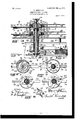
- Fig. 3 is a detail vertical sectional representation of a portion of the clock-casing, its face and cover plates, and contact-making devices connected with the arbor or main spindle of the clock mechanism, the clockwork having been omitted from this view.
- Fig. 4 is a horizontal section taken on line 4 in said Fig. 3 looking in the direction of the arrow X
- Fig. 5 is a similar sectional representation taken on line 5 5 in said Fig. 3 looking in the direction of the said arrow X.
- Fig. 6 is a horizontal section taken on line 5 5 in said Fig. 3, but looking in the direction of the arrow Y; and Fig. 7 is a similar section of the same parts, but showing the parts in theiroperative posi tions during electrical contact.
- Fig. 8 is a perspective view of a sleeve and contact-post provided with a contact-making brush.
- the reference character 1 indicates the complete electric timing apparatus or alarm embodying the principles of the present invention, the same comprising a suitable base or casing 2 of any suitable material, such as wood or metal, the latter being preferably used because it is best suited to withstand any rough usage, dirt, and other deteriorating effects due to its use in factories and electroplating plants.
- a clock work or mechanism 3 Suitably secured upon the said base 2 is a clock work or mechanism 3 of any of the well-known and approved constructions, the framework of which may be suitably insulated from the said base 2, as will be clearly understood.
- the said clock- Suitably secured or connected with the frame portions 5 of the framework is a support 6, carrying a block 7 of 1 suitable insulating material, upon which is secured, by means of screws 8, a bracket 9, which is provided with a pair of spring contacts or brushes 10, extending toward and upon opposite sides of the main arbor or spindle 4 and its parts, substantially as illustrated in Figs. 2 and 3 of the drawings.
- the casing or support 2 is provided at its side or other suitable part with a block 11 of a suitable insulating material, and connected with this block 11 are a pair of terminal binding-screws 12 and 13 of any well-known construction, to which, respectively, are attached the terminal wires 14 and 15 of an electric circuit leading from the main electrical source or supply.
- a wire 16 Connected with the binding-screw 12 is a wire 16, which is also secured at its opposite end with one of the screws 8 of the bracket 9.
- Another wire, 17, has its one end suitably connected with any part of the frame of the clockwork, the opposite end of said wire 17 being attached to a binding-post of any usual form of electric bell or other suitable annunciator 18.
- a wire 19 Leading from another binding-post of the said electric bell or anunciator 18 is a wire 19, which in turn is connected at its opposite end with the binding-screw 13.
- the main arbor or spindle 4 of the clockwork extends in an upward direction through an opening in the upper portion 5' of the framework, the spindle or arbor being preferably provided with an annular shoulder 20, upon which rests a disk or plate 21.
- the extreme upper end of the said arbor or spindle 4 is provided with a screw-thread 22 and a nut 23, and arranged upon the said arbor or spindle 4 with its lower end resting upon the said disk or plate 21 is a metal tube 24, which is secured to the said arbor or spindle by means of a pin 25 or other suitable holding means that the said tube 24 will turn with the said spindle or arbor when the latter is driven from the gear mechanism of the clockwork 3.
- a pinion 27 Resting upon the said disk or plate 21 is another disk, 26, upon which is rotatively arranged a pinion 27, which is aflixed upon the lower portion of the tube 24.
- a post 28 extending in an upward direction from the portion 5, is a gear 29, in mesh with the said pinion 27 for producing a rotary motion of the said post 28, as will be clearly understood.
- a second pinion 30 is operatively secured upon said post 28, the said pinion 30 engaging with the gear 31 of a tube 32, which is slipped over the tube 24 and is capable of an independent rotary motion upon said tube 24.
- a tube 33 Surrounding a portion of the said tube 32 is a tube 33, made of a suitable insulating material, the lower end, portion of the said tube 33 being made in the form of an annular flange 34, which rests upon the upper surface of the gear 31, substai'itially in the manner shown in said Fig. 3 of the drawings.
- a tube or sleeve 35 Upon the said insulating-tube 33 is arranged a tube or sleeve 35, of metal, and upon the u pper or other suitable portion of the said tube or sleeve I have ailixed a hub 36, which is provided with a segmental portion 37, extending from one of its sides and has a contactproducing post 38, with which is pivotally connected a contact-brush 39, substantially as illustrated in Figs.
- a metal or other suitable cover-plate 40 is provided, above which is supported upon suitably-disposed sleeves 41 and is secured by means of screws 42 or in any other suitable manner a facedate 43.
- the said coverplate 40 is made with a centrally-disposed opening 44, and the face-plate 43 has a similarly-located opening 45, through which the main arbor or spindle 4 and the various tubes carried upon said arbor or spindle extend and retate, as will be clearly evident.
- the previously-mentioned spring contacts or brushes 10 extend in sliding contact with the metal tube or sleeve 35, substantially as illustrated.
- ahub 46 Suitably secured upon the upper and preferably reduced end portion of the tube 32 and resting upon an annular oflset upon said tube 32 and upon the upper edge of the insulating tube 33 is ahub 46, having a downwardly-extending annular flange 47, forming with the said hub an annular chamber 48, the said hub 46 being provided also with a laterally-extending hour hand or pointer 49.
- a ring or nut 50 Connected with the lower portion of the said hub 46 is a ring or nut 50, by means of which is secured upon said hub and against the under marginal edge of the flange 47 a yielding contact arm or hand 51, which is capable of a movement independent of the said hour-hand 49, but under normal conditions moves in vertical alinement with the said hand 4E).
- the said arm or hand 51 has an upwardly-project ing post 52, which extends into the chamber 48 and has attached to said post 52 the end of a spring 53, which has its other end suitably secured upon the inner face of the annular flange 47.
- the tendency of said spring 53 is to move a pin or projection 54 upon the said arm or hand 51 normally against a pin or projection 55, extending from the outer surface of the annular flanges 47, whereby the said arm or hand 51 will move in alinement with the hour-hand unless the said arm or hand 51 meets an obstruction in its path of movement, substantially asand for the purposes to be hereinafter more fully described.
- a rod 57 Suitably secured against the under surface of the said arm or hand 51 by means of solder 56 or in any other suitable manner is the fixed end portion of a rod 57, made from suitable spring-wire, the said rod being made with.a curved portion 58 and a larger curved contacting end member 59, which is adapted to be brought in slidable contact with the con-- tact-post 38 when the movement of the said arm or hand 51 is arrested, as will hereinafter appear.
- a hub 60 Suitably secured upon the upper end portion of the tube 24, arranged directly upon the main arbor or spindle 4 and at a point below. the screw portion 22 and nut 23, is a hub 60, having a downwardly-extending annular flange 61, forming with the said hub an annular chamber 62, the said hub being provided also with a laterally-extending minute hand or pointer 63.
- the said hub 60 is provided with a downwardly extending sleeve portion 64, upon which is arranged a sleeve 65, of insulating material.
- a collar or sleeve 66 Immovably arranged upon said insulating-sleeve is a collar or sleeve 66, formed with a radially-extending arm 67, having an upwardly-projecting contact-finger 68 at its free end, substantially as illustrated in Figs. 3, 6, and 7, the previously-mentioned spring contact or brush 39 being in slidable contact with the outer cylindrical surface of the said sleeve or collar 66, as clearly shown in Fig. 5 of the drawings.
- a ring or nut 69 Connected with the lower portion of the said hub 60 is a ring or nut 69, by means of which is secured upon said hub and against the under marginal edge of the flange 61 a yielding contact arm or hand 70, which is capable of a movement independent of the said minutehand 63, but under normal conditions moves in vertical alinement with the said hand 63. That such normal vertical alinement and simultaneous rotary movements of the minutehand 63 and the said contact arm or hand 70 may be had the said arm or hand 70 has an upwardly-projecting post 71, which extends into the chamber 62 and has attached to said post the end of a spring 72, which has its other end suitably secured upon the inner surface of the annular flange 61, as clearly illustrated in Fig. 4 of the drawings.
- this spring 72 is to move a pin or projection 73 upon the said arm or hand 70 normally against a pin or projection 74, which extends from the outer surface of the annular flange 61, whereby the'said arm or hand 70 will move in alinement with the minute-hand 63 unless said arm or hand 70 meets an obstruction in its path .of movement, substantially as and for the purposes to be presently set forth.
- a rod 76 made from suitable spring-wire, the said rod being formed with a curved portion 77 and a larger curved contacting end member 78, which is adapted to be brought in slidable contact with the contact-finger 68, previously mentioned, when the movement of the said arm or hand is arrested, as will hereinafter appear.
- Fig. 1 of the drawings it will be seen that the face-plate 43 is divided into concentric rings of holes or perforations 79, the three outer rows of perforations representing minutes; but some of said rows may also be divided into suitable divisions representing seconds.
- the fourth inner row of divisions represents the hours and quarterhours, while the extreme inner row of divisions represents still another subdivision of the quarter-hours.
- suitable electric contacts can bemade by means of the arm or hand 70 and the bell rung at intervals less than one hour; but when one or more pins or studs 80 are inserted in any predetermined perforations of the two inner rows of perforations suitable electric contacts can be made by means of the arm or hand 51 and the bell rung at suitable intervals of hours or more than an hour, as will be clearly understood.
- a bracket 81 Connected with the apparatus is a bracket 81, having perforations 82 for the reception of the pins or studs not in use.
- ⁇ Vhen a pin or pins 80 are employed with the three outer circular rows of perforations 7 9 in the faceplate 43, the movement of the arm or hand as soon as it is brought against a pin or stud is arrested, and thereby causes the contact portion 78 of the rod 76 to be brought against the contactfinger 68 in the manner indicated in Fig.
- a time-alarm the combination, with a casing, a cover-plate for closing said casing, a face-plate outside of said cover-plate, said faceplate being provided with stop-pin-receiving perforations, a stop-pin adapted to be inserted in a stop-pin perforation, of a clockwork mounted in said casing, a main arbor or spindle, a hub and an index-hand connected with said arbor or spindle, a pin-engaging arm yieldably connected with said hub adapted to be brought in engagement with a stop-pin inserted in the face-plate, a support on said insulated sleeve, a contact-post on said support, and a spring-rod secured to said pin-engaging arm provided with a curved contacting portion adapted to be brought in slid able engagement with said contact-post, and an electric circuit including an electric alarm connected respectively with the said insulated sleeve and the said main arbor or spindle and a clock work, substantially as and for the purposes
- the cou'ibination with a casing, a cover-plate for closing said casing, a face-plate outside of said cover-plate, said faceplate being provided with stop-pin-receiving perforations, a stop-pin adapted to be inserted in a stop-pin perforation, of a clockwork mounted in said casing, a main arbor or spindle, an insulated sleeve on said arbor or spindle, a hub and an index-hand connected with said arbor or spindle, a pin-engaging arm yieldably connected with said hub adapted to be brought in engagement with a stoppin inserted in the face-plate, a support on said insulated sleeve, :1.
- a timealarm the combination with a casing, a cover-plate for closing said casing, a face-plate outside of said cover-plate, said face plate being providedwith stop-pirrreceiving perforations, a stop-pin adapted to be inserted in a stop-pin perforation, of a clockwork mounted, in said casing, a main arbor or spindle, an insulated sleeve upon said arbor or spindle, a chambered hub and index-hand connected with said arbor or spindle, a pin-engag- ICC ing arm on said hub adapted to be brought in engagement with a stop-pin inserted in the face-plate, a spring in said chambered hub having its ends respectively connected with said pin-engaging arm and with a portion of the chambered hub, and means on said pin-engaging arm and hub for retaining said arm normally in Vertical alinement with the indexhand, and an electric circuit including an electricalarm connected respectively with said insulated sleeve and said main arbor
- a time-alarm the combination, with a casing, a cover-plate for closing said casing, a face-plate outside of said cover-plate, said faceplate being provided with stop-pin-receiving perforations, a stop-pin adapted to be inserted in a stop-pin perforation, of a clockwork mounted in said casing, a main arbor or spindle, an insulated sleeve upon said arbor or spindle, a chambered hub and index-hand connected With said arbor or spindle, a pin-engaging arm on said hub adapted to be brought in engagement with a stop-pin inserted in the face-plate, a spring in said chambered hub having its ends respectively connected with said pin-engaging arm and with a portion of the chambered hub, and means on said pin-engaging arm and hub for retaining said arm normally in vertical alinement with the indexhand, a bracket and contact-brushes on said bracket in slidable engagement with said insulated sleeve, and an
- a time-alarm the combination, with a casing, a cover-plate for closing said casing, a face-plate outside of said cover-plate, said faceplate being provided With stop-pin-receiving perforations, a sto p-pin adapted to be inserted in a stop-pin perforation, of a clockwork mounted in said casing, a main arbor or spindle, an insulated sleeve upon said arbor or spindle, a chambered hub and index-hand connected with said arbor or spindle, a pin-engaging arm on said hub adapted to be brought in engagement with a stop-pin inserted in the face-plate, a spring in said chambered hub having its ends respectively connected with said phi-engaging arm and with a portion of the chambered hub, and means on said pin-engaging arm and hub for retaining said arm normally in vertical alinement with the indexhand, a support on said insulated sleeve, a
- a time-alarm the combination, with a casing, a cover-plate for closingsaid casing, a face-plate outside of said coverplate,said faceplate being provided with stop-pin-receiving perforations, a stop-pin adapted to be inserted in a stop-pin perforation, of a clockwork mounted in said casing, a main arbor or spindle, an insulated sleeve upon said arbor or spindle, a chambered hub and index-hand connected with said arbor or spindle, a pin-engaging arm on said hub adapted to be brought in engagement with a stop-pin inserted in the face-plate, a spring in said chambered hub having its ends respectively connected with said pin-engaging arm and with a portion of the chambered hub, and means on said pin-engaging arm and hub for retaining said arm normally in vertical alinement with the indexhand, a support on said insulated sleeve, a contact-post on said support, and a spring-rod secured
- a time-alarm the combination, with a casing, a cover-plate for closing said casing, a face-plate outside of said cover-plate, said faceplate being provided with stop-pin-receiving perforations, a stop-pin adapted to be inserted in a stop-pin perforation, of a clockwork mounted in said casing, a main arbor orspindle, a tube 24 onsaid arbor or spindle, a chambered hub on said tube, said hub being provided with a minute-hand, a pin-engaging arm on said hub adapted to be brought in engagement with a stop-pin inserted in said faceplate, a spring in said chambered hub having its ends respectively connected with said pinengaging arm 70 and with a portion of the chambered hub, means on said pin-engaging arm 70 and hub for retaining said arm normally in vertical alinement with the minutehand, a tube 32 arranged over said tube 24, an insulated sleeve 35, a chambered hub on said tube 32,
- a stop-pin adapted to be inserted in a stop pin perforation, of a clockwork chambered hub, means on said pin-engaging i arm and hub for retaining said arm normally in vertical alinement with the minutehand, a tube 32 arranged over said tube 24, an insulated sleeve 35, a chambered hub on said tube 32, said hub being provided with an hour-hand, a pin-engaging arm 51 on said hub adapted to be brought in engagement with a stop-pin inserted in said face-plate, a spring in said chambered hubhaving its ends respectively connected with said pin-engaging arm 51 and with a portion of the chambered hub, means on said pin-engaging arm 51 and hub for retaining said arm normally in vertical alinement with the hour-hand, a bracket and contact-brushes on said bracket in slidable engagement with said insulated sleeve, and an electric circuit connected respectively with
- a time-alarm the combination, with a casing, a cover-plate for closing said casing, a face-plate outside of said cover-plate, said face-plate being provided with stop-pinreceiving perforations, a stop-pin adapted to be inserted in a stop-pin perforation, of a clockwork mounted in said casing, a main arbor or spindle, a tube 24 on said arbor or spindle, a chambered hub on said tube, said hub being provided with a minute-hand, a pin-engaging arm 70 on said hub adapted to be brought in engagement with a stop-pin inserted in said face-plate,a spring in said chambered hub having its ends respectively connected with said pin-engaging arm 70 and with a portion of the chambered hub, means on said pin-engaging arm 70 and hub for retaining said arm normally in vertical alinement with the minute-hand, an insulated support 66 upon said hub, a contact linger or post 68 on said support, a spring-rod 76
- the combination with a casing, a cover-plate for closing said casing, a face-plate outside of said cover-plate, said faceplate being provided with stop-pin-receiving perforations, a stop-pin adapted to be inserted in a stop-pin perforation, of a.
- a clock mechanism andits main arbor or spin- 1 a clock mechanism and its main arbor orspindlc, of a chambered hub connected with said arbor or spindle, said hub carrying an indexhand, a pin-engaging arm yieldingly connected with said hub, and a spring in said chambered hub havingits ends respectively connected with said pin-engaging arm and with a portion of the chambered hub, substantially as and for the purposes set forth.
- a time-alarm the combination, with a clock mechanism and its main arbor orspindle, of a chambered hub connected with said arbor or spindle, said hub carrying an ind exhand, a pin-engaging arm yieldingly connected with said hub, a spring in said chambered hub having its ends respectively connected with said pin-engaging arm and with aportion of the chambered hub, and means on said pinengaging arm and said hub for retaining said arm normally in vertical alinement with the index-hand, substantially as and for the purposes set forth.
- the combination With dlc, of a chambered h uh connected with said arbor or spindle, said hub carrying an indexhand, a pin-engaging arm yieldingly connected with said hub, a spring in said chambered hub having its ends respectively connected with said pin-engagingarm and with a portion of the chambered hub, and means on said pinengaging arm and said hub for retaining said arm normally in vertical alinement with the index-hand, consisting of a vertical pin or stud on said arm, and a laterally-extending pin or stud on said hub adapted to engage said pin or stud on said arm, substantially as and for the purposes set forth.
Landscapes
- Physics & Mathematics (AREA)
- Acoustics & Sound (AREA)
- General Physics & Mathematics (AREA)
- Electromechanical Clocks (AREA)
Description
PATENTED FEB. 21, 1905.
F. HERMANGE.
ELECTRIC TIME ALARM.
APPLICATION FILED JULY 30, 1904.
3 SHEETSSHEET l.
INVENTORZ LESSESj 7%W No. 782,849. PATENTED FEB. 21, 1905. P. HERMANCE.
ELECTRIC TIME ALARM.
APPLICATION FILED JULY 30, 1904.
3 SHEETSSHEET 2 s ll i WlTNESSES: INVENTOR:
PHIL KW err'm'anca, Q g
ATTORNEY Patented February 21, 1905.
PATENT OFFICE.
FRANK HERMANCE, OF UNION HILL, NEW JERSEY.
ELECTRIC TIME-ALARM.
SPECIFICATION formingpart of Letters Patent No. 782,849, dated February 21, 1905.
Application filed July 30, 1904. Serial No. 218,856.
To all whom it vim/7 1 concern.-
Be it known that I, FRANK HERMANCE, a citizen of the United States, residing at Union Hill, in the county of Hudson and State of New Jersey,have invented certain new and useful improvements in Electric Time Alarms; and .I do hereby declare the following to be a full, clear, and exact description of the invention, such as will enable others skilled in the art to which it appertains to make and use the same, reference being had to the accompanying drawings, and to numerals of reference marked thereon, which form a part of this specification.
The present invention has reference generally to that class of apparatus known as timealarms, usually in the form of a clock and its actuating mechanism provided with an electric circuit, an electric alarm, and contacts to be used with contact-producing means, which may be variously disposed upon the face of the clock to complete an electric circuit through the alarm at any predetermined time or times.
The invention is especially designed to pro vide a simple and efl'ectively-operating timing apparatus of the character hereinafter more particularly specified and which is especially designed for use in connection with electroplating or galvanoplastic processes to notify the operator when the articles which are to be plated have been in the bath the proper length of time.
A further object of this invention is to provide a timing apparatus which is especially adapted for timing the electrolytic action in a series of separate tanks or baths and for various other purposes where it is desired to sound an alarm at predetermined intervals.
My invention consists, primarily, in the novel electrictiming apparatus or alarm hereinafter more particularly set forth; and, furthermore, this invention consists in the novel arrangements and combinations of devices and parts, as well as in the details of the construction of the same, all of which will be more fully described in the following specification and then finally embodied in the clauses of the claim, which are appended to and which form an essential part of this specification.
The invention is clearly illustrated in the accompanying drawings, in which Figure l is a front or face view of a timing apparatus or alarm embodying the principles of the present invention, and Fig. 2 is a plan view of certain parts of the apparatus with the clock-casing shown in section. Fig. 3 is a detail vertical sectional representation of a portion of the clock-casing, its face and cover plates, and contact-making devices connected with the arbor or main spindle of the clock mechanism, the clockwork having been omitted from this view. Fig. 4: is a horizontal section taken on line 4 in said Fig. 3 looking in the direction of the arrow X, and Fig. 5 is a similar sectional representation taken on line 5 5 in said Fig. 3 looking in the direction of the said arrow X. Fig. 6 is a horizontal section taken on line 5 5 in said Fig. 3, but looking in the direction of the arrow Y; and Fig. 7 is a similar section of the same parts, but showing the parts in theiroperative posi tions during electrical contact. Fig. 8 is a perspective view of a sleeve and contact-post provided with a contact-making brush.
Similar characters of reference are employed in the above-described views to indicate corresponding parts.
Referring now to the several ligures of the drawings, the reference character 1 indicates the complete electric timing apparatus or alarm embodying the principles of the present invention, the same comprising a suitable base or casing 2 of any suitable material, such as wood or metal, the latter being preferably used because it is best suited to withstand any rough usage, dirt, and other deteriorating effects due to its use in factories and electroplating plants. Suitably secured upon the said base 2 is a clock work or mechanism 3 of any of the well-known and approved constructions, the framework of which may be suitably insulated from the said base 2, as will be clearly understood. The said clock- Suitably secured or connected with the frame portions 5 of the framework is a support 6, carrying a block 7 of 1 suitable insulating material, upon which is secured, by means of screws 8, a bracket 9, which is provided with a pair of spring contacts or brushes 10, extending toward and upon opposite sides of the main arbor or spindle 4 and its parts, substantially as illustrated in Figs. 2 and 3 of the drawings.
From an inspection of Figs. 1 and 2 of the drawings it will be seen that the casing or support 2 is provided at its side or other suitable part with a block 11 of a suitable insulating material, and connected with this block 11 are a pair of terminal binding- screws 12 and 13 of any well-known construction, to which, respectively, are attached the terminal wires 14 and 15 of an electric circuit leading from the main electrical source or supply. Connected with the binding-screw 12 is a wire 16, which is also secured at its opposite end with one of the screws 8 of the bracket 9. Another wire, 17, has its one end suitably connected with any part of the frame of the clockwork, the opposite end of said wire 17 being attached to a binding-post of any usual form of electric bell or other suitable annunciator 18. Leading from another binding-post of the said electric bell or anunciator 18 is a wire 19, which in turn is connected at its opposite end with the binding-screw 13.
Referring now to Fig. 3 of the drawings, it will be seen that the main arbor or spindle 4 of the clockwork extends in an upward direction through an opening in the upper portion 5' of the framework, the spindle or arbor being preferably provided with an annular shoulder 20, upon which rests a disk or plate 21. The extreme upper end of the said arbor or spindle 4 is provided with a screw-thread 22 and a nut 23, and arranged upon the said arbor or spindle 4 with its lower end resting upon the said disk or plate 21 is a metal tube 24, which is secured to the said arbor or spindle by means of a pin 25 or other suitable holding means that the said tube 24 will turn with the said spindle or arbor when the latter is driven from the gear mechanism of the clockwork 3. Resting upon the said disk or plate 21 is another disk, 26, upon which is rotatively arranged a pinion 27, which is aflixed upon the lower portion of the tube 24. Upon a post 28, extending in an upward direction from the portion 5, is a gear 29, in mesh with the said pinion 27 for producing a rotary motion of the said post 28, as will be clearly understood. A second pinion 30 is operatively secured upon said post 28, the said pinion 30 engaging with the gear 31 of a tube 32, which is slipped over the tube 24 and is capable of an independent rotary motion upon said tube 24. Surrounding a portion of the said tube 32 is a tube 33, made of a suitable insulating material, the lower end, portion of the said tube 33 being made in the form of an annular flange 34, which rests upon the upper surface of the gear 31, substai'itially in the manner shown in said Fig. 3 of the drawings. Upon the said insulating-tube 33 is arranged a tube or sleeve 35, of metal, and upon the u pper or other suitable portion of the said tube or sleeve I have ailixed a hub 36, which is provided with a segmental portion 37, extending from one of its sides and has a contactproducing post 38, with which is pivotally connected a contact-brush 39, substantially as illustrated in Figs. 3, 5, and 8 of the drawings, the purposes of which will be presently more fully set forth. From an inspection of the said Fig. 3 of the drawings it will be clearly understood that while the main arbor or spindle 4 and its tube 24 are making twelve revolutions the intermediately-placed pinions and gears will cause the tube 32 and the tubes 33 and 35 to make during the same time but one revolution in the manner of the usual clockwork construction.
To prevent dirt and dust from getting into the casing 2 and to the clockwork therein, a metal or other suitable cover-plate 40 is provided, above which is supported upon suitably-disposed sleeves 41 and is secured by means of screws 42 or in any other suitable manner a facedate 43. The said coverplate 40 is made with a centrally-disposed opening 44, and the face-plate 43 has a similarly-located opening 45, through which the main arbor or spindle 4 and the various tubes carried upon said arbor or spindle extend and retate, as will be clearly evident.
The previously-mentioned spring contacts or brushes 10 extend in sliding contact with the metal tube or sleeve 35, substantially as illustrated.
Suitably secured upon the upper and preferably reduced end portion of the tube 32 and resting upon an annular oflset upon said tube 32 and upon the upper edge of the insulating tube 33 is ahub 46, having a downwardly-extending annular flange 47, forming with the said hub an annular chamber 48, the said hub 46 being provided also with a laterally-extending hour hand or pointer 49. Connected with the lower portion of the said hub 46 is a ring or nut 50, by means of which is secured upon said hub and against the under marginal edge of the flange 47 a yielding contact arm or hand 51, which is capable of a movement independent of the said hour-hand 49, but under normal conditions moves in vertical alinement with the said hand 4E). That such normal vertical alinement and simultaneous rotary movements of the hour-hand 49 and the said contact arm or hand 51 may be had, the said arm or hand 51 has an upwardly-project ing post 52, which extends into the chamber 48 and has attached to said post 52 the end of a spring 53, which has its other end suitably secured upon the inner face of the annular flange 47. The tendency of said spring 53 is to move a pin or projection 54 upon the said arm or hand 51 normally against a pin or projection 55, extending from the outer surface of the annular flanges 47, whereby the said arm or hand 51 will move in alinement with the hour-hand unless the said arm or hand 51 meets an obstruction in its path of movement, substantially asand for the purposes to be hereinafter more fully described. Suitably secured against the under surface of the said arm or hand 51 by means of solder 56 or in any other suitable manner is the fixed end portion of a rod 57, made from suitable spring-wire, the said rod being made with.a curved portion 58 and a larger curved contacting end member 59, which is adapted to be brought in slidable contact with the con-- tact-post 38 when the movement of the said arm or hand 51 is arrested, as will hereinafter appear.
Suitably secured upon the upper end portion of the tube 24, arranged directly upon the main arbor or spindle 4 and at a point below. the screw portion 22 and nut 23, is a hub 60, having a downwardly-extending annular flange 61, forming with the said hub an annular chamber 62, the said hub being provided also with a laterally-extending minute hand or pointer 63. The said hub 60 is provided with a downwardly extending sleeve portion 64, upon which is arranged a sleeve 65, of insulating material. Immovably arranged upon said insulating-sleeve is a collar or sleeve 66, formed with a radially-extending arm 67, having an upwardly-projecting contact-finger 68 at its free end, substantially as illustrated in Figs. 3, 6, and 7, the previously-mentioned spring contact or brush 39 being in slidable contact with the outer cylindrical surface of the said sleeve or collar 66, as clearly shown in Fig. 5 of the drawings. Connected with the lower portion of the said hub 60 is a ring or nut 69, by means of which is secured upon said hub and against the under marginal edge of the flange 61 a yielding contact arm or hand 70, which is capable of a movement independent of the said minutehand 63, but under normal conditions moves in vertical alinement with the said hand 63. That such normal vertical alinement and simultaneous rotary movements of the minutehand 63 and the said contact arm or hand 70 may be had the said arm or hand 70 has an upwardly-projecting post 71, which extends into the chamber 62 and has attached to said post the end of a spring 72, which has its other end suitably secured upon the inner surface of the annular flange 61, as clearly illustrated in Fig. 4 of the drawings. The tendency of this spring 72 is to move a pin or projection 73 upon the said arm or hand 70 normally against a pin or projection 74, which extends from the outer surface of the annular flange 61, whereby the'said arm or hand 70 will move in alinement with the minute-hand 63 unless said arm or hand 70 meets an obstruction in its path .of movement, substantially as and for the purposes to be presently set forth. Suitably secured against the under surface of the said arm or hand 70, by means of solder 75 or in any other suitable manner,
is the fixed end portion of a rod 76, made from suitable spring-wire, the said rod being formed with a curved portion 77 and a larger curved contacting end member 78, which is adapted to be brought in slidable contact with the contact-finger 68, previously mentioned, when the movement of the said arm or hand is arrested, as will hereinafter appear.
Referring now to Fig. 1 of the drawings, it will be seen that the face-plate 43 is divided into concentric rings of holes or perforations 79, the three outer rows of perforations representing minutes; but some of said rows may also be divided into suitable divisions representing seconds. The fourth inner row of divisions represents the hours and quarterhours, while the extreme inner row of divisions represents still another subdivision of the quarter-hours. Thus by inserting one or more pins or studs in any predetermined perforations 79 in the three outer rows of perforations suitable electric contacts can bemade by means of the arm or hand 70 and the bell rung at intervals less than one hour; but when one or more pins or studs 80 are inserted in any predetermined perforations of the two inner rows of perforations suitable electric contacts can be made by means of the arm or hand 51 and the bell rung at suitable intervals of hours or more than an hour, as will be clearly understood. Connected with the apparatus is a bracket 81, having perforations 82 for the reception of the pins or studs not in use.
The method of operation may be briefly described as follows: Ordinarily when there are no pins or studs 80 inserted in the faceplate 43 the hour and minute hands 49 and 63, respectively, with their correspondinglyplaced arms or hands 51 and 70, will rotate about the said face-plate in the usual manner of any clock construction. hen, however, a pin or stud 80 is inserted in a perforation 79 of one of the two innermost rows or perforations, the arm or hand 51 as soon as it is brought against the said pin or stud and thereby arrested in its motion, causes the contact portion 59 of the rod 57 to be brought against the contact-post 38 (see Fig. 5) and establishes a complete electric circuit from the terminal 12 through the wire 16, the bracket 9, the brushes 10, the tube or sleeve 35, the sleeve 36 and support 37, the post 38, the rod 57 and the arm or hand 51, through the main arbor or spindle and the parts thereon, the frame of the clockwork, the wire 17, and the alarm 18,flnally completing the circuit through the return-wire 19 to the terminal 13, whereby the alarm is sounded indicating to the attendant that it is time to remove the articles from the plating-tank. \Vhen a pin or pins 80 are employed with the three outer circular rows of perforations 7 9 in the faceplate 43, the movement of the arm or hand as soon as it is brought against a pin or stud is arrested, and thereby causes the contact portion 78 of the rod 76 to be brought against the contactfinger 68 in the manner indicated in Fig. 7 of the drawings and establishes a complete electric circuit from the terminal 12 through the wire 16, the bracket 7, the brush 8, the tube or sleeve 35, the sleeve 36 and support 37, the contact-post 38, the brush 39 of said post 38, the sleeve 66 and an arm 67, the linger 68, the rod 7 6 and arm or hand 70, through the main arbor or spindle and parts thereon, the frame of the clockwork, the wire 17, and the alarm 18, finally completing the circuit through the return-wire 19 to the terminal 13, whereby the alarm is again sounded upon the bell. As soon as the pins or studs are removed the arrangements of the said arms or hands 51 and 70 are such that they automatically return to their intiai positions directly beneath the hour and minute hands, respectively. \Vith this arrangement just described it will be evident that any arrangement of perforations 7 9 and pins 80 may be had with the face-plate and the time may be subdivided to give an unlimited range of variation between contacts, and in manipulating a series of tanks pins corresponding to the number of such tanks can be set at suitable intervals in the face-plate of the apparatus and the alarm sounded in the manner previously stated. After contact has been established with one pin and the alarm sounded the attendant removes this pin, replaces it in the plate or rack 81, whereby the arrested arm or hand is returned to its position beneath the hour or minute hand, the parts moving on until the next pin 80 is met, when the alarm is again sounded, and so on, according to the number of pins employed.
1 am aware that some changes may be made in the arrangements and combinations of the devices and parts, as well as in the details of the construction of the same, without departing from the scope of this invention. Hence 1 do not limit my invention to the exact arrangements and combinations of the devices and parts set forth in the foregoing specification and illustrated in the accompanying drawings, nor do I confine myself to the exact details of the construction of the said parts.
Having thus described my invention, what I claim is 1. 1n atime-alarm, the combination, with a casing, a cover-plate for closing said casing, a face-plate outside of said cover-plate, said face plate being provided with stop-pin-receiving perforations, a stop-pin adapted to be inserted in a stop-pin perforation, of a clockwork rsasae spindle, a hub and an index-hand connected with said arbor or spindle, a pin-engaging arm yieldably connected with said hub adapted to be brought in engagement with a stop-pin inserted in the face-plate, and an electric circuit including an electric alarm connected respectively with said insulated sleeve and said main arbor or spindle and clockwork, substantially as and for the purposes set forth.
2. In a time-alarm, the combination, with a casing, a cover-plate for closing said casing, a face-plate outside of said cover-plate, said faceplate being provided with stop-pin-receiving perforations, a stop-pin adapted to be inserted in a stop-pin perforation, of a clockwork mounted in said casing, a main arbor or spindle, a hub and an index-hand connected with said arbor or spindle, a pin-engaging arm yieldably connected with said hub adapted to be brought in engagement with a stop-pin inserted in the face-plate, a support on said insulated sleeve, a contact-post on said support, and a spring-rod secured to said pin-engaging arm provided with a curved contacting portion adapted to be brought in slid able engagement with said contact-post, and an electric circuit including an electric alarm connected respectively with the said insulated sleeve and the said main arbor or spindle and a clock work, substantially as and for the purposes set forth.
3. In a time-alarm, the cou'ibination, with a casing, a cover-plate for closing said casing, a face-plate outside of said cover-plate, said faceplate being provided with stop-pin-receiving perforations, a stop-pin adapted to be inserted in a stop-pin perforation, of a clockwork mounted in said casing, a main arbor or spindle, an insulated sleeve on said arbor or spindle, a hub and an index-hand connected with said arbor or spindle, a pin-engaging arm yieldably connected with said hub adapted to be brought in engagement with a stoppin inserted in the face-plate, a support on said insulated sleeve, :1. contactpost on said support, and a spring-rod secured to said pin-engaging arm provided with a curved contacting portion adapted to be brought in slidable engagement with said contact-post, a bracket and contact-brushes on said bracket in slidable engagement with said insulated sleeve, and an electric circuit connected respectively with said bracket and said main arbor or spindle and clockwork, substantially as and for the purposes set forth.
4:. In a timealarm, the combination with a casing, a cover-plate for closing said casing, a face-plate outside of said cover-plate, said face plate being providedwith stop-pirrreceiving perforations, a stop-pin adapted to be inserted in a stop-pin perforation, of a clockwork mounted, in said casing, a main arbor or spindle, an insulated sleeve upon said arbor or spindle, a chambered hub and index-hand connected with said arbor or spindle, a pin-engag- ICC ing arm on said hub adapted to be brought in engagement with a stop-pin inserted in the face-plate, a spring in said chambered hub having its ends respectively connected with said pin-engaging arm and with a portion of the chambered hub, and means on said pin-engaging arm and hub for retaining said arm normally in Vertical alinement with the indexhand, and an electric circuit including an electricalarm connected respectively with said insulated sleeve and said main arbor or spindle and clockwork, substantially as and for the purposes set forth.
5. In a time-alarm, the combination, with a casing, a cover-plate for closing said casing, a face-plate outside of said cover-plate, said faceplate being provided with stop-pin-receiving perforations, a stop-pin adapted to be inserted in a stop-pin perforation, of a clockwork mounted in said casing, a main arbor or spindle, an insulated sleeve upon said arbor or spindle, a chambered hub and index-hand connected With said arbor or spindle, a pin-engaging arm on said hub adapted to be brought in engagement with a stop-pin inserted in the face-plate, a spring in said chambered hub having its ends respectively connected with said pin-engaging arm and with a portion of the chambered hub, and means on said pin-engaging arm and hub for retaining said arm normally in vertical alinement with the indexhand, a bracket and contact-brushes on said bracket in slidable engagement with said insulated sleeve, and an electric circuit connected respectively with said bracket and said main arbor or spindle and, clockwork, substantially as and for the purposes set forth.
6. In a time-alarm, the combination, with a casing, a cover-plate for closing said casing, a face-plate outside of said cover-plate, said faceplate being provided With stop-pin-receiving perforations, a sto p-pin adapted to be inserted in a stop-pin perforation, of a clockwork mounted in said casing, a main arbor or spindle, an insulated sleeve upon said arbor or spindle, a chambered hub and index-hand connected with said arbor or spindle, a pin-engaging arm on said hub adapted to be brought in engagement with a stop-pin inserted in the face-plate, a spring in said chambered hub having its ends respectively connected with said phi-engaging arm and with a portion of the chambered hub, and means on said pin-engaging arm and hub for retaining said arm normally in vertical alinement with the indexhand, a support on said insulated sleeve, a
arbor or spindle and clockwork, substantially as and for the purposes set forth,
7. In a time-alarm, the combination, with a casing, a cover-plate for closingsaid casing, a face-plate outside of said coverplate,said faceplate being provided with stop-pin-receiving perforations, a stop-pin adapted to be inserted in a stop-pin perforation, of a clockwork mounted in said casing, a main arbor or spindle, an insulated sleeve upon said arbor or spindle, a chambered hub and index-hand connected with said arbor or spindle, a pin-engaging arm on said hub adapted to be brought in engagement with a stop-pin inserted in the face-plate, a spring in said chambered hub having its ends respectively connected with said pin-engaging arm and with a portion of the chambered hub, and means on said pin-engaging arm and hub for retaining said arm normally in vertical alinement with the indexhand, a support on said insulated sleeve, a contact-post on said support, and a spring-rod secured to said pin-engaging arm provided with a curved contacting portion adapted to be brought in slidable engagement with said contact-post, a bracket and contact-brushes on said bracket in slidable engagement with said insulated sleeve, and an electric circuit connected respectively with said bracket and said main arbor or spindle and clockwork, substantially as and for the purposes set forth.
8. In a time-alarm, the combination, with a casing, a cover-plate for closing said casing, a face-plate outside of said cover-plate, said faceplate being provided with stop-pin-receiving perforations, a stop-pin adapted to be inserted in a stop-pin perforation, of a clockwork mounted in said casing, a main arbor orspindle, a tube 24 onsaid arbor or spindle, a chambered hub on said tube, said hub being provided with a minute-hand, a pin-engaging arm on said hub adapted to be brought in engagement with a stop-pin inserted in said faceplate, a spring in said chambered hub having its ends respectively connected with said pinengaging arm 70 and with a portion of the chambered hub, means on said pin-engaging arm 70 and hub for retaining said arm normally in vertical alinement with the minutehand, a tube 32 arranged over said tube 24, an insulated sleeve 35, a chambered hub on said tube 32, said hub being provided with an hour hand, a pin-engaging arm 51 on said hub adapted to be brought in engagement with a stop-pin inserted in said face-plate, a spring in said chambered hub having its ends respectively connected with said pinengaging arm 51 and with a portion of the chambered hub, means on said pin-engaging arm 51 and hub for retaining said arm normally in vertical alinement with the hour-hand, and an electric circuit including an electric alarm con nected respectively with said insulated sleeve and said main arbor or spindle and clockwork, substantially as and for the purposes set forth.
'9. In a time-alarm, the combination, with a casing, a cover-plate for closing said casing, a
face-plate outside of said coverplate,said faceplate being provided with stop pmrece1v1ng perforations, a stop-pin adapted to be inserted in a stop pin perforation, of a clockwork chambered hub, means on said pin-engaging i arm and hub for retaining said arm normally in vertical alinement with the minutehand, a tube 32 arranged over said tube 24, an insulated sleeve 35, a chambered hub on said tube 32, said hub being provided with an hour-hand, a pin-engaging arm 51 on said hub adapted to be brought in engagement with a stop-pin inserted in said face-plate, a spring in said chambered hubhaving its ends respectively connected with said pin-engaging arm 51 and with a portion of the chambered hub, means on said pin-engaging arm 51 and hub for retaining said arm normally in vertical alinement with the hour-hand, a bracket and contact-brushes on said bracket in slidable engagement with said insulated sleeve, and an electric circuit connected respectively with said bracket and said main arbor or spindle and clockwork, substantially as and for the purposes set forth.
10. In a time-alarm, the combination, with a casing, a cover-plate for closing said casing, a face-plate outside of said cover-plate, said face-plate being provided with stop-pinreceiving perforations, a stop-pin adapted to be inserted in a stop-pin perforation, of a clockwork mounted in said casing, a main arbor or spindle, a tube 24 on said arbor or spindle, a chambered hub on said tube, said hub being provided with a minute-hand, a pin-engaging arm 70 on said hub adapted to be brought in engagement with a stop-pin inserted in said face-plate,a spring in said chambered hub having its ends respectively connected with said pin-engaging arm 70 and with a portion of the chambered hub, means on said pin-engaging arm 70 and hub for retaining said arm normally in vertical alinement with the minute-hand, an insulated support 66 upon said hub, a contact linger or post 68 on said support, a spring-rod 76 secured to said pin-engaging arm 70 pro vided with a curved contacting portion adapted to be brought in slidable engagement with said contact finger or post 68, a tube 32 arranged over said tube 24, and an insulated sleeve 35, a chambered hub on said tube 32, said hub be ing provided with an hour-hand, a pin-engaging arm 51 on said hub adapted to be brought in engagement with astop-pin inserted in said face-plate, a spring in said chambered hub having its ends respectively connected with veasae said pin-engaging arm 51 and with a portion of the chambered hub, means on said pin-ea gaging arm 51 and hub for retaining said arm normally in vertical alinement with the hourhand, a support on said insulated sleeve 35, a contact-post 38 on said support, a contactbrush between said post 38 and said insulated support 66, and aspring-rod 57 secured to said pin-engaging arm 51 provided with a curved contacting portion adapted to be brought in slidable engagement with said contact-post 38, and an electric circuit including an electric alarm connected respectively with said sleeve and said main arboror spindleand clockwork, substantially as and for the purposes set forth.
11. In a time-alarm, the combination, with a casing, a cover-plate for closing said casing, a face-plate outside of said cover-plate, said faceplate being provided with stop-pin-receiving perforations, a stop-pin adapted to be inserted in a stop-pin perforation, of a. clockwork mounted in said casing, a main arbor or spindle, a tube 24 on said arboror spindle, a chambered hub on said tube, said hub being provided with a minute-hand, a pin-engaging arm 70 on said hub adapted to be brought in engagement with a stop-pin inserted in said face-plate, a spring in said chambered hub having its ends respectively connected with said pin-engaging arm '70 and with a portion of the chambered hub, means on said pin-engaging arm 7 O and hub for retaining said arm normally in vertical alinement with the minute-hand, an insulated support 66 upon said hub, a contact linger or post (58 or said support, a spring-rod 76 secured to said pin-engaging arm 70 provided with a curved contacting portion adapted to be brought in slidable engagement with said contact linger or post 68, a tube SQarranged over said tube 2 1;, and an insulated sleeve 35, a chambered hub on said tube 32, said hub being provided with an hour-hand, a ran-engaging arm 51 on said hub adapted to be brought in engagen'lent with a stop-pin inserted in said face-plate, a spring in said chambered hub having its ends respectively connected with said pin-engaging arm 51 and with a portion of the chambered hub, means on said pin-engaging arm 51. and hub for retaining said arm normally in vertical alinement with the hour-hand, a support on said insulated sleeve 35, a contact-post 38 on said support, a contact-brush between said post 38 and said insulated support (56, a springrod 57 secured to said pin-engaging arm 51 provided with a curved contacting portion adapted to be brought in slidable engagement with said contact-post 38, a bracket and contact-brushes on said bracket in slidable engagement with said insulated sleeve, and an electric circuit connected respectively with said bracket and said main arbor or spindle and clockwork, substantially as and for the purposes set forth.
12. In a time-alarn'i, the combination, with a clock mechanism andits main arbor or spin- 1 a clock mechanism and its main arbor orspindlc, of a chambered hub connected with said arbor or spindle, said hub carrying an indexhand, a pin-engaging arm yieldingly connected with said hub, and a spring in said chambered hub havingits ends respectively connected with said pin-engaging arm and with a portion of the chambered hub, substantially as and for the purposes set forth.
13. In a time-alarm, the combination, with a clock mechanism and its main arbor orspindle, of a chambered hub connected with said arbor or spindle, said hub carrying an ind exhand, a pin-engaging arm yieldingly connected with said hub, a spring in said chambered hub having its ends respectively connected with said pin-engaging arm and with aportion of the chambered hub, and means on said pinengaging arm and said hub for retaining said arm normally in vertical alinement with the index-hand, substantially as and for the purposes set forth.
14. In a time-alarm, the combination, With dlc, of a chambered h uh connected with said arbor or spindle, said hub carrying an indexhand, a pin-engaging arm yieldingly connected with said hub, a spring in said chambered hub having its ends respectively connected with said pin-engagingarm and with a portion of the chambered hub, and means on said pinengaging arm and said hub for retaining said arm normally in vertical alinement with the index-hand, consisting of a vertical pin or stud on said arm, and a laterally-extending pin or stud on said hub adapted to engage said pin or stud on said arm, substantially as and for the purposes set forth.
In testimony that I claim the invention set forth above I have hereunto set my hand this 29th day of July, 1904:.
FRANK HERMANCE.
Witnesses:
FREDK. C. FRAENTZEL, GEO. D. RICHARDS.
Priority Applications (1)
| Application Number | Priority Date | Filing Date | Title |
|---|---|---|---|
| US21885604A US782849A (en) | 1904-07-30 | 1904-07-30 | Electric time-alarm. |
Applications Claiming Priority (1)
| Application Number | Priority Date | Filing Date | Title |
|---|---|---|---|
| US21885604A US782849A (en) | 1904-07-30 | 1904-07-30 | Electric time-alarm. |
Publications (1)
| Publication Number | Publication Date |
|---|---|
| US782849A true US782849A (en) | 1905-02-21 |
Family
ID=2851335
Family Applications (1)
| Application Number | Title | Priority Date | Filing Date |
|---|---|---|---|
| US21885604A Expired - Lifetime US782849A (en) | 1904-07-30 | 1904-07-30 | Electric time-alarm. |
Country Status (1)
| Country | Link |
|---|---|
| US (1) | US782849A (en) |
Cited By (1)
| Publication number | Priority date | Publication date | Assignee | Title |
|---|---|---|---|---|
| USD596507S1 (en) * | 2008-06-25 | 2009-07-21 | Mr. Christmas Incorporated | Clock |
-
1904
- 1904-07-30 US US21885604A patent/US782849A/en not_active Expired - Lifetime
Cited By (1)
| Publication number | Priority date | Publication date | Assignee | Title |
|---|---|---|---|---|
| USD596507S1 (en) * | 2008-06-25 | 2009-07-21 | Mr. Christmas Incorporated | Clock |
Similar Documents
| Publication | Publication Date | Title |
|---|---|---|
| US782849A (en) | Electric time-alarm. | |
| US719390A (en) | Electric time-switch. | |
| US1469056A (en) | Reminding device | |
| US2098965A (en) | Clock | |
| US890134A (en) | Alarm-clock. | |
| US553890A (en) | zeidlee | |
| US601850A (en) | Program-clock | |
| US900529A (en) | Program attachment for clocks. | |
| US459917A (en) | Contact for electric programme-clocks | |
| US1268656A (en) | Call-bell clock. | |
| US636656A (en) | Electric time-alarm. | |
| US576528A (en) | Alarm-clock | |
| US853119A (en) | Electric alarm-clock. | |
| US885513A (en) | Electric time-switch. | |
| US556428A (en) | Electric program-clock | |
| US770902A (en) | Program-clock. | |
| US957397A (en) | Electric alarm-clock. | |
| US246211A (en) | David rousseau | |
| US486399A (en) | garnett | |
| US428854A (en) | Electric programme-clock | |
| US270639A (en) | Joseph i | |
| US577128A (en) | Signal | |
| US478155A (en) | Electric alarm-clock | |
| US1233559A (en) | Reminder-clock. | |
| US400750A (en) | Alarm system |