US7826148B2 - Aspheric lens structures and fabrication methods thereof - Google Patents
Aspheric lens structures and fabrication methods thereof Download PDFInfo
- Publication number
- US7826148B2 US7826148B2 US11/706,192 US70619207A US7826148B2 US 7826148 B2 US7826148 B2 US 7826148B2 US 70619207 A US70619207 A US 70619207A US 7826148 B2 US7826148 B2 US 7826148B2
- Authority
- US
- United States
- Prior art keywords
- aspheric
- lens
- lens component
- back surface
- component
- Prior art date
- Legal status (The legal status is an assumption and is not a legal conclusion. Google has not performed a legal analysis and makes no representation as to the accuracy of the status listed.)
- Active, expires
Links
- 238000000034 method Methods 0.000 title claims abstract description 18
- 238000004519 manufacturing process Methods 0.000 title abstract description 9
- 239000000758 substrate Substances 0.000 claims description 21
- 238000000465 moulding Methods 0.000 claims description 11
- 229920002120 photoresistant polymer Polymers 0.000 claims description 10
- 238000001459 lithography Methods 0.000 claims description 8
- 238000005498 polishing Methods 0.000 claims description 3
- 230000007704 transition Effects 0.000 claims description 3
- 230000009977 dual effect Effects 0.000 abstract description 12
- 239000002131 composite material Substances 0.000 description 6
- 239000011347 resin Substances 0.000 description 6
- 229920005989 resin Polymers 0.000 description 6
- 239000011521 glass Substances 0.000 description 4
- 230000003287 optical effect Effects 0.000 description 3
- 239000000463 material Substances 0.000 description 2
- 238000012986 modification Methods 0.000 description 2
- 230000004048 modification Effects 0.000 description 2
- 239000005304 optical glass Substances 0.000 description 2
- 239000004033 plastic Substances 0.000 description 2
- 229920003023 plastic Polymers 0.000 description 2
- 239000000126 substance Substances 0.000 description 2
- XUIMIQQOPSSXEZ-UHFFFAOYSA-N Silicon Chemical compound [Si] XUIMIQQOPSSXEZ-UHFFFAOYSA-N 0.000 description 1
- 238000003491 array Methods 0.000 description 1
- 230000001413 cellular effect Effects 0.000 description 1
- 239000011248 coating agent Substances 0.000 description 1
- 238000000576 coating method Methods 0.000 description 1
- 238000003384 imaging method Methods 0.000 description 1
- 239000002991 molded plastic Substances 0.000 description 1
- 238000004806 packaging method and process Methods 0.000 description 1
- 239000010453 quartz Substances 0.000 description 1
- 229910052710 silicon Inorganic materials 0.000 description 1
- 239000010703 silicon Substances 0.000 description 1
- VYPSYNLAJGMNEJ-UHFFFAOYSA-N silicon dioxide Inorganic materials O=[Si]=O VYPSYNLAJGMNEJ-UHFFFAOYSA-N 0.000 description 1
- 239000002904 solvent Substances 0.000 description 1
Images


Classifications
-
- B—PERFORMING OPERATIONS; TRANSPORTING
- B29—WORKING OF PLASTICS; WORKING OF SUBSTANCES IN A PLASTIC STATE IN GENERAL
- B29D—PRODUCING PARTICULAR ARTICLES FROM PLASTICS OR FROM SUBSTANCES IN A PLASTIC STATE
- B29D11/00—Producing optical elements, e.g. lenses or prisms
- B29D11/00009—Production of simple or compound lenses
- B29D11/00019—Production of simple or compound lenses with non-spherical faces, e.g. toric faces
-
- B—PERFORMING OPERATIONS; TRANSPORTING
- B29—WORKING OF PLASTICS; WORKING OF SUBSTANCES IN A PLASTIC STATE IN GENERAL
- B29D—PRODUCING PARTICULAR ARTICLES FROM PLASTICS OR FROM SUBSTANCES IN A PLASTIC STATE
- B29D11/00—Producing optical elements, e.g. lenses or prisms
- B29D11/00009—Production of simple or compound lenses
- B29D11/00365—Production of microlenses
- B29D11/00375—Production of microlenses by moulding lenses in holes through a substrate
Definitions
- the invention relates to aspheric lens structures, and more particularly to lens structures with dual aspheric surfaces and fabrication methods thereof.
- Aspheric lenses have some optical advantages, but cannot be easily produced by traditional glass grinding and polishing techniques. Aspheric lenses with all glass elements may be large and excessively expensive for use in compact digital cameras or accessories built into a cellular phone.
- Aspheric elements are typically produced by molding plastics or low melt temperature glasses. While molded plastic elements are inexpensive to produce, the level of precision of the lenses is not always sufficient for high-resolution cameras, particularly if a plastic element is used primarily as a focusing element. Further, a conventional aspheric lens with a single aspheric surface is produced by molding a resin on a plate and is then replicated to create an array of aspheric lens on the plate for wafer level package application. The ability to mass produces molding lenses is limited, thus, manufacture thereof is expensive.
- FIG. 1 is a schematic view of conventional aspheric lens fabricated by molding.
- a transparent resin 3 is injected on a plate 1 .
- a die 2 moves toward the substrate to mold the transparent resin 3 into a lens with an aspheric surface 3 a on the plate 1 , the die then returns to its original position.
- An array of aspheric lens 3 on the plate 1 is replicated by repeating the described molding procedure for wafer level package application.
- FIG. 2 is a schematic view of another conventional hybrid aspheric lens fabricated by transferring an aspheric composite layer on a convex lens.
- conventional hybrid lenses in which an aspheric composite layer is formed on a single lens of optical glass or lens plate serving as a parent material, are commercially practical as a means for forming an aspheric lens at relatively low cost.
- the forming die 10 has a smoothed concave transfer face 20 for forming an aspheric composite layer 30 thereon.
- a convex lens 40 made of optical glass is placed on and fixed to the forming die 10 via a support frame 50 .
- the ultraviolet-curing resin 30 thereby fills the entire space between the transfer face 20 and the convex lens 40 .
- the ability to mass produce aspheric composite layer transferred to a convex lens is limited and thus expensive to manufacture.
- the invention is directed to aspheric lens structures with dual aspheric surfaces fabricated by lithography. Optical performance can be improved in comparison to single aspheric surface lens plates.
- the invention provides an aspheric lens structure comprising a first lens component with an aspheric top surface disposed on a second lens component, wherein the interface between the first lens component and the second lens component is spherical.
- the second lens component comprises an aspheric back surface, wherein the radius of curvature of the aspheric top surface of the first lens component is different than the radius of curvature of the aspheric back surface of the second lens component.
- the second lens component comprises a planar back surface and a third lens component is disposed on the planar back surface of the second component.
- the third lens component comprises an aspheric back surface, wherein the radius of curvature of the aspheric top surface of the first lens component is different than the radius of curvature of the aspheric back surface of the third lens component.
- the invention further provides a method for fabricating an aspheric lens structure, comprising providing a substrate, perforating the substrate with a hole, inserting a ball lens in the hole exposing a pre-curvature of the ball lens, applying a layer of black dye on the substrate to obstruct an unnecessary part of the ball lens, conformably forming a photoresist layer on the substrate and the exposed ball lens, and forming the photoresist layer by lithography to create an aspheric surface on the ball lens configured as a first lens component.
- the method for fabricating an aspheric lens structure further comprises polishing the back of the ball lens to create a planar back surface configured as a second lens component, and forming a third lens component with an aspheric back surface on the planar back surface of the second component.
- the method for fabricating an aspheric lens structure further comprises removing the ball lens, creating a cavity, and forming a second lens component with an aspheric back surface in the cavity.
- FIG. 1 is a schematic view of conventional aspheric lens fabricated by molding
- FIG. 2 is a schematic view of another conventional hybrid aspheric lens fabricated by transferring an aspheric composite layer to a convex lens;
- FIGS. 3-10 show cross sections illustrating fabrication of an exemplary embodiment of an aspheric lens structure with dual aspheric surfaces of the invention.
- FIGS. 11-12 show cross sections illustrating fabrication of another exemplary embodiment of an aspheric lens structure with dual aspheric surfaces of the invention.
- FIGS. 3-10 show cross sections illustrating fabrication of an exemplary embodiment of an aspheric lens structure with dual aspheric surfaces of the invention.
- a substrate 100 is provided.
- Substrate 100 comprises a bulk silicon substrate, a quartz substrate or a glass substructure.
- Substrate 100 is configured as a carrier of the aspheric lens structure.
- the substrate 100 is perforated to create a through hole 105 .
- the diameter of the through hole 105 is equal to or less than the diameter of a yet to be described ball lens.
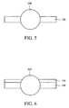
- a ball lens 200 is inserted in the through hole 105 exposing a pre-curvature of the ball lens 200 , as shown in FIG. 5 .
- a layer of black dye 110 is applied to the substrate for obstructing an unnecessary part of the ball lens 200 .
- the layer of black dye 110 is preferably formed by coating on the substrate 100 configured as a buffer for the aspheric lens structure.
- a photoresist layer 120 is conformably formed on the black dye layer 110 and the exposed ball lens 200 .
- a mask 300 such as a phase transition mask is disposed over the main region corresponding to the aspheric lens.
- the phase transition mask includes a half tone mask or a gray tone mask.
- An aspheric lens component 125 with an aspheric surface 125 a is formed on the ball lens 200 by forming a photoresist layer by lithography to serve as a first lens component as depicted in FIG. 8 .
- the ball lens 200 is configured as a second lens component with a spherical back surface.
- the preferable aspheric lens component 125 can optionally be heated and reflowed to change the radius of curvature of the aspheric surface 125 a . Further, the aspheric lens component 125 can optionally be molded to change the curvature of the aspheric surface 125 a.
- the back of the ball lens 200 is planarized to create a planar back surface.
- CMP chemical mechanical planarization
- a third lens component 210 with an aspheric back surface 210 a is subsequently formed on the planar back surface of the ball lens 200 , as depicted in FIG. 10 .
- the third lens component 210 can be formed by molding.
- the radius of curvature of the aspheric top surface 125 a of the first lens component 125 is different than the radius of curvature of the aspheric back surface 210 a of the third lens component 210 .
- An array of aspheric lens structures with dual aspheric surfaces on a substrate can thus be fabricated by lithography. There are additional steps not mentioned here, which are required to complete the array of aspheric lens structures with dual aspheric surfaces, but which are not essential to an understanding of the invention.
- FIGS. 11-12 are cross sections illustrating fabrication of another exemplary embodiment of an aspheric lens structure with dual aspheric surfaces of the invention.
- the ball lens 200 is preferably composed of a UV dissolvable resin.
- the UV dissolvable ball lens 200 is irradiated by UV light and is removed by chemical solvent leaving a cavity.
- an alternative second lens component 250 with an aspheric back surface 250 a is formed in the cavity.
- the alternative second lens component 250 can be formed by molding.
- the radius of curvature of the aspheric top surface 125 a of the first lens component 125 is different than the radius of curvature of the aspheric back surface 250 a of the alternative second lens component 250 .
- Other steps not shown are undertaken to complete the aspheric lens structures with dual aspheric surfaces.
- the invention is advantageous in that aspheric lens structures with dual aspheric surfaces on a plate are fabricated by lithography.
- the radius of curvature and surface profile of the aspheric lens structure can be precisely adjusted and controlled.
- the ability to mass produce aspheric lens structure arrays with dual aspheric surfaces on a plate can be achieved for wafer scale packaging. Optic performance, in comparison with conventional single aspheric surface lens plates, can also be improved.
Landscapes
- Engineering & Computer Science (AREA)
- Health & Medical Sciences (AREA)
- Manufacturing & Machinery (AREA)
- Ophthalmology & Optometry (AREA)
- Mechanical Engineering (AREA)
- Casting Or Compression Moulding Of Plastics Or The Like (AREA)
- Lenses (AREA)
Abstract
Description
Claims (17)
Priority Applications (3)
| Application Number | Priority Date | Filing Date | Title |
|---|---|---|---|
| US11/706,192 US7826148B2 (en) | 2007-02-15 | 2007-02-15 | Aspheric lens structures and fabrication methods thereof |
| TW096119294A TWI359285B (en) | 2007-02-15 | 2007-05-30 | Aspheric lens structure and fabrication methods th |
| CN2007101066881A CN101246225B (en) | 2007-02-15 | 2007-06-15 | Aspheric lens structures fabrication methods |
Applications Claiming Priority (1)
| Application Number | Priority Date | Filing Date | Title |
|---|---|---|---|
| US11/706,192 US7826148B2 (en) | 2007-02-15 | 2007-02-15 | Aspheric lens structures and fabrication methods thereof |
Publications (2)
| Publication Number | Publication Date |
|---|---|
| US20080198481A1 US20080198481A1 (en) | 2008-08-21 |
| US7826148B2 true US7826148B2 (en) | 2010-11-02 |
Family
ID=39706423
Family Applications (1)
| Application Number | Title | Priority Date | Filing Date |
|---|---|---|---|
| US11/706,192 Active 2028-08-11 US7826148B2 (en) | 2007-02-15 | 2007-02-15 | Aspheric lens structures and fabrication methods thereof |
Country Status (3)
| Country | Link |
|---|---|
| US (1) | US7826148B2 (en) |
| CN (1) | CN101246225B (en) |
| TW (1) | TWI359285B (en) |
Cited By (2)
| Publication number | Priority date | Publication date | Assignee | Title |
|---|---|---|---|---|
| USD727189S1 (en) * | 2013-12-17 | 2015-04-21 | Agilent Technologies, Inc. | Aspheric lens with integral flange for optical measurement instrument |
| US20160056899A1 (en) * | 2014-08-20 | 2016-02-25 | Tsinghua University | Led optical communication receiving lens and led optical communication system |
Families Citing this family (2)
| Publication number | Priority date | Publication date | Assignee | Title |
|---|---|---|---|---|
| JP5587991B2 (en) * | 2009-06-02 | 2014-09-10 | フラウンホーファー−ゲゼルシャフト・ツール・フェルデルング・デル・アンゲヴァンテン・フォルシュング・アインゲトラーゲネル・フェライン | Lens and manufacturing method thereof |
| DE102017213065B3 (en) * | 2017-04-13 | 2018-07-05 | Christian-Albrechts-Universität Zu Kiel | A process for the production of plano-convex lens elements and for the production of a packaged device at the wafer level |
Citations (7)
| Publication number | Priority date | Publication date | Assignee | Title |
|---|---|---|---|---|
| JPS6057801A (en) | 1983-09-09 | 1985-04-03 | Canon Inc | Aspherical lens by cementing |
| US4537473A (en) * | 1982-11-05 | 1985-08-27 | Corning Glass Works | Fiducial surfaces |
| US4641929A (en) * | 1984-10-22 | 1987-02-10 | U.S. Philips Corporation | Biaspherical lens |
| US4890905A (en) * | 1985-06-10 | 1990-01-02 | U.S. Philips Corp. | Replica lens and method of manufacturing same |
| US5004330A (en) * | 1989-03-17 | 1991-04-02 | Hoya Corporation | Aspherical glass lens element formed by a low dispersion glass material |
| US6049430A (en) | 1998-11-12 | 2000-04-11 | Seagate Technology | High numerical aperture objective lens manufacturable in wafer form |
| US20020135883A1 (en) * | 2001-03-23 | 2002-09-26 | Takao Nishikawa | Microlens array, manufacturing method thereof and optical instrument |
-
2007
- 2007-02-15 US US11/706,192 patent/US7826148B2/en active Active
- 2007-05-30 TW TW096119294A patent/TWI359285B/en active
- 2007-06-15 CN CN2007101066881A patent/CN101246225B/en active Active
Patent Citations (7)
| Publication number | Priority date | Publication date | Assignee | Title |
|---|---|---|---|---|
| US4537473A (en) * | 1982-11-05 | 1985-08-27 | Corning Glass Works | Fiducial surfaces |
| JPS6057801A (en) | 1983-09-09 | 1985-04-03 | Canon Inc | Aspherical lens by cementing |
| US4641929A (en) * | 1984-10-22 | 1987-02-10 | U.S. Philips Corporation | Biaspherical lens |
| US4890905A (en) * | 1985-06-10 | 1990-01-02 | U.S. Philips Corp. | Replica lens and method of manufacturing same |
| US5004330A (en) * | 1989-03-17 | 1991-04-02 | Hoya Corporation | Aspherical glass lens element formed by a low dispersion glass material |
| US6049430A (en) | 1998-11-12 | 2000-04-11 | Seagate Technology | High numerical aperture objective lens manufacturable in wafer form |
| US20020135883A1 (en) * | 2001-03-23 | 2002-09-26 | Takao Nishikawa | Microlens array, manufacturing method thereof and optical instrument |
Cited By (3)
| Publication number | Priority date | Publication date | Assignee | Title |
|---|---|---|---|---|
| USD727189S1 (en) * | 2013-12-17 | 2015-04-21 | Agilent Technologies, Inc. | Aspheric lens with integral flange for optical measurement instrument |
| US20160056899A1 (en) * | 2014-08-20 | 2016-02-25 | Tsinghua University | Led optical communication receiving lens and led optical communication system |
| US9571204B2 (en) * | 2014-08-20 | 2017-02-14 | Tsinghua University | LED optical communication receiving lens and LED optical communication system |
Also Published As
| Publication number | Publication date |
|---|---|
| TW200834119A (en) | 2008-08-16 |
| TWI359285B (en) | 2012-03-01 |
| US20080198481A1 (en) | 2008-08-21 |
| CN101246225B (en) | 2010-12-01 |
| CN101246225A (en) | 2008-08-20 |
Similar Documents
| Publication | Publication Date | Title |
|---|---|---|
| US8432625B2 (en) | Lens and method for manufacturing same | |
| US6432328B2 (en) | Method for forming planar microlens and planar microlens obtained thereby | |
| US8120858B2 (en) | Micro lens, method and apparatus for manufacturing micro lens, and camera module including micro lens | |
| JP3968545B2 (en) | Manufacturing method of microlens array | |
| KR101087695B1 (en) | Different materials integrated lens unit and camera module having same | |
| US9184199B2 (en) | Optical assembly including plenoptic microlens array | |
| KR100561844B1 (en) | Micro Lens Array and Manufacturing Method Thereof | |
| US7794633B2 (en) | Method and apparatus for fabricating lens masters | |
| EP1014114A1 (en) | Microlens array plate, manufacture thereof, and display device | |
| JP4161602B2 (en) | Microlens array, manufacturing method thereof, and optical apparatus | |
| CN102470616A (en) | Method for fabricating wafer-level optical components | |
| US20100002312A1 (en) | Over-molded glass lenses and method of forming the same | |
| JP2007519969A (en) | Variable focus lens package | |
| US7826148B2 (en) | Aspheric lens structures and fabrication methods thereof | |
| US8154794B2 (en) | Imaging lens and method of manufacturing the same | |
| JPH11211902A (en) | Flat microlens array | |
| JP4781001B2 (en) | Compound lens manufacturing method | |
| US9919455B2 (en) | Methods for forming a lens plate for an integrated camera using UV-transparent molds and methods for forming UV-transparent molds | |
| US8287781B2 (en) | Imprinting method for making optical components | |
| KR100519769B1 (en) | Manufacturing method of hybrid microlens array | |
| KR100990605B1 (en) | Master lens manufacturing mold and master lens manufacturing method using this mold | |
| JP2003222708A (en) | Optical element and manufacturing method thereof | |
| JP2002228804A (en) | Manufacturing method of optical element, optical element by the manufacturing method, display element and display device having the optical element, and imaging element and imaging apparatus having the optical element | |
| Wippermann et al. | Endurance analysis of optical master stamps for UV-replication | |
| Yu et al. | Self-alignment Micro-lens by Gradient of Surface Tension |
Legal Events
| Date | Code | Title | Description |
|---|---|---|---|
| AS | Assignment |
Owner name: VISERA TECHNOLOGIES COMPANY LIMITED, TAIWAN Free format text: ASSIGNMENT OF ASSIGNORS INTEREST;ASSIGNORS:ZUNG, PAI-CHUN PETER;SHIUNG, SHIN-CHANG;WANG, WEI-KO;AND OTHERS;REEL/FRAME:018994/0649 Effective date: 20070209 |
|
| STCF | Information on status: patent grant |
Free format text: PATENTED CASE |
|
| AS | Assignment |
Owner name: OMNIVISION TECHNOLOGIES, INC., CALIFORNIA Free format text: ASSIGNMENT OF ASSIGNORS INTEREST;ASSIGNOR:VISERA TECHNOLOGIES COMPANY LIMITED;REEL/FRAME:026563/0895 Effective date: 20110624 |
|
| AS | Assignment |
Owner name: VISERA TECHNOLOGIES COMPANY LIMITED, TAIWAN Free format text: CORRECTIVE ASSIGNMENT TO CORRECT THE ASSIGNEE PREVIOUSLY RECORDED ON REEL 026563 FRAME 0895. ASSIGNOR(S) HEREBY CONFIRMS THE ASSIGNEES ARE OMNIVISION TECHNOLOGIES, INC. AND VISERA TECHNOLOGIES COMPANY LIMITED;ASSIGNOR:VISERA TECHNOLOGIES COMPANY LIMITED;REEL/FRAME:026736/0545 Effective date: 20110624 Owner name: OMNIVISION TECHNOLOGIES, INC., CALIFORNIA Free format text: CORRECTIVE ASSIGNMENT TO CORRECT THE ASSIGNEE PREVIOUSLY RECORDED ON REEL 026563 FRAME 0895. ASSIGNOR(S) HEREBY CONFIRMS THE ASSIGNEES ARE OMNIVISION TECHNOLOGIES, INC. AND VISERA TECHNOLOGIES COMPANY LIMITED;ASSIGNOR:VISERA TECHNOLOGIES COMPANY LIMITED;REEL/FRAME:026736/0545 Effective date: 20110624 |
|
| FPAY | Fee payment |
Year of fee payment: 4 |
|
| MAFP | Maintenance fee payment |
Free format text: PAYMENT OF MAINTENANCE FEE, 8TH YEAR, LARGE ENTITY (ORIGINAL EVENT CODE: M1552) Year of fee payment: 8 |
|
| MAFP | Maintenance fee payment |
Free format text: PAYMENT OF MAINTENANCE FEE, 12TH YEAR, LARGE ENTITY (ORIGINAL EVENT CODE: M1553); ENTITY STATUS OF PATENT OWNER: LARGE ENTITY Year of fee payment: 12 |