US7823617B2 - Spring powered sliding drywall taping tool with auto cutter - Google Patents
Spring powered sliding drywall taping tool with auto cutter Download PDFInfo
- Publication number
- US7823617B2 US7823617B2 US11/385,025 US38502506A US7823617B2 US 7823617 B2 US7823617 B2 US 7823617B2 US 38502506 A US38502506 A US 38502506A US 7823617 B2 US7823617 B2 US 7823617B2
- Authority
- US
- United States
- Prior art keywords
- trim
- actuator
- blade
- tool
- drywall
- Prior art date
- Legal status (The legal status is an assumption and is not a legal conclusion. Google has not performed a legal analysis and makes no representation as to the accuracy of the status listed.)
- Active, expires
Links
Images


Classifications
-
- B—PERFORMING OPERATIONS; TRANSPORTING
- B65—CONVEYING; PACKING; STORING; HANDLING THIN OR FILAMENTARY MATERIAL
- B65H—HANDLING THIN OR FILAMENTARY MATERIAL, e.g. SHEETS, WEBS, CABLES
- B65H35/00—Delivering articles from cutting or line-perforating machines; Article or web delivery apparatus incorporating cutting or line-perforating devices, e.g. adhesive tape dispensers
- B65H35/0006—Article or web delivery apparatus incorporating cutting or line-perforating devices
- B65H35/002—Hand-held or table apparatus
- B65H35/0026—Hand-held or table apparatus for delivering pressure-sensitive adhesive tape
- B65H35/0033—Hand-held or table apparatus for delivering pressure-sensitive adhesive tape and affixing it to a surface
-
- B—PERFORMING OPERATIONS; TRANSPORTING
- B44—DECORATIVE ARTS
- B44D—PAINTING OR ARTISTIC DRAWING, NOT OTHERWISE PROVIDED FOR; PRESERVING PAINTINGS; SURFACE TREATMENT TO OBTAIN SPECIAL ARTISTIC SURFACE EFFECTS OR FINISHES
- B44D3/00—Accessories or implements for use in connection with painting or artistic drawing, not otherwise provided for; Methods or devices for colour determination, selection, or synthesis, e.g. use of colour tables
- B44D3/38—Cord line chalkers
-
- E—FIXED CONSTRUCTIONS
- E04—BUILDING
- E04F—FINISHING WORK ON BUILDINGS, e.g. STAIRS, FLOORS
- E04F21/00—Implements for finishing work on buildings
- E04F21/02—Implements for finishing work on buildings for applying plasticised masses to surfaces, e.g. plastering walls
- E04F21/026—Implements for finishing work on buildings for applying plasticised masses to surfaces, e.g. plastering walls for applying adhesive or joint compound to joint tapes, in particular drywall tapes
-
- E—FIXED CONSTRUCTIONS
- E04—BUILDING
- E04F—FINISHING WORK ON BUILDINGS, e.g. STAIRS, FLOORS
- E04F21/00—Implements for finishing work on buildings
- E04F21/165—Implements for finishing work on buildings for finishing joints, e.g. implements for raking or filling joints, jointers
-
- E—FIXED CONSTRUCTIONS
- E04—BUILDING
- E04F—FINISHING WORK ON BUILDINGS, e.g. STAIRS, FLOORS
- E04F21/00—Implements for finishing work on buildings
- E04F21/165—Implements for finishing work on buildings for finishing joints, e.g. implements for raking or filling joints, jointers
- E04F21/1657—Implements for finishing work on buildings for finishing joints, e.g. implements for raking or filling joints, jointers for applying tape to joints, e.g. drywall taper tools
-
- Y—GENERAL TAGGING OF NEW TECHNOLOGICAL DEVELOPMENTS; GENERAL TAGGING OF CROSS-SECTIONAL TECHNOLOGIES SPANNING OVER SEVERAL SECTIONS OF THE IPC; TECHNICAL SUBJECTS COVERED BY FORMER USPC CROSS-REFERENCE ART COLLECTIONS [XRACs] AND DIGESTS
- Y10—TECHNICAL SUBJECTS COVERED BY FORMER USPC
- Y10T—TECHNICAL SUBJECTS COVERED BY FORMER US CLASSIFICATION
- Y10T156/00—Adhesive bonding and miscellaneous chemical manufacture
- Y10T156/12—Surface bonding means and/or assembly means with cutting, punching, piercing, severing or tearing
- Y10T156/1348—Work traversing type
- Y10T156/1352—Work traversing type with liquid applying means
- Y10T156/1361—Cutting after bonding
-
- Y—GENERAL TAGGING OF NEW TECHNOLOGICAL DEVELOPMENTS; GENERAL TAGGING OF CROSS-SECTIONAL TECHNOLOGIES SPANNING OVER SEVERAL SECTIONS OF THE IPC; TECHNICAL SUBJECTS COVERED BY FORMER USPC CROSS-REFERENCE ART COLLECTIONS [XRACs] AND DIGESTS
- Y10—TECHNICAL SUBJECTS COVERED BY FORMER USPC
- Y10T—TECHNICAL SUBJECTS COVERED BY FORMER US CLASSIFICATION
- Y10T156/00—Adhesive bonding and miscellaneous chemical manufacture
- Y10T156/17—Surface bonding means and/or assemblymeans with work feeding or handling means
- Y10T156/1788—Work traversing type and/or means applying work to wall or static structure
- Y10T156/1795—Implement carried web supply
-
- Y—GENERAL TAGGING OF NEW TECHNOLOGICAL DEVELOPMENTS; GENERAL TAGGING OF CROSS-SECTIONAL TECHNOLOGIES SPANNING OVER SEVERAL SECTIONS OF THE IPC; TECHNICAL SUBJECTS COVERED BY FORMER USPC CROSS-REFERENCE ART COLLECTIONS [XRACs] AND DIGESTS
- Y10—TECHNICAL SUBJECTS COVERED BY FORMER USPC
- Y10T—TECHNICAL SUBJECTS COVERED BY FORMER US CLASSIFICATION
- Y10T156/00—Adhesive bonding and miscellaneous chemical manufacture
- Y10T156/17—Surface bonding means and/or assemblymeans with work feeding or handling means
- Y10T156/1798—Surface bonding means and/or assemblymeans with work feeding or handling means with liquid adhesive or adhesive activator applying means
-
- Y—GENERAL TAGGING OF NEW TECHNOLOGICAL DEVELOPMENTS; GENERAL TAGGING OF CROSS-SECTIONAL TECHNOLOGIES SPANNING OVER SEVERAL SECTIONS OF THE IPC; TECHNICAL SUBJECTS COVERED BY FORMER USPC CROSS-REFERENCE ART COLLECTIONS [XRACs] AND DIGESTS
- Y10—TECHNICAL SUBJECTS COVERED BY FORMER USPC
- Y10T—TECHNICAL SUBJECTS COVERED BY FORMER US CLASSIFICATION
- Y10T156/00—Adhesive bonding and miscellaneous chemical manufacture
- Y10T156/18—Surface bonding means and/or assembly means with handle or handgrip
Definitions
- the present invention relates to drywall taping tools and more particularly to a drywall taping tool with a powered cutter.
- BAZOOKA automatic drywall taping devices in production today
- BAZOOKA is a registered trademark
- Normally tools of this type have a tape (or paper) cutter incorporated into the design. This cutter is usually activated by pulling a movable tube down against a spring. This requires a movement of the arm while holding the apelooka. This can be very difficult in tight spots, at odd angles or when reaching high up joints.
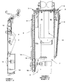
- FIG. 1 shows a side view of the tool in the idle position.
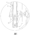
- FIG. 2 shows a Section C-C from FIG. 1 .
- FIG. 3 shows Detail F from FIG. 1 .
- FIG. 4 shows the tool in the cocking position.
- FIG. 5 shows Section C-C from FIG. 4 .
- FIG. 6 shows the tool in the cocked and ready position.
- FIG. 7 shows Section C-C from FIG. 6 .
- FIG. 8 shows Detail F. from FIG. 6 .
- FIG. 9 shows the tool in the triggered and cut position.
- FIG. 10 shows Section C-C from FIG. 9 .
- FIG. 11 shows Detail F. from FIG. 9 .
- the present invention relates to a drywall taping tool that includes a standard drywall taping tool such as a BAZOOKA tool with an elongated handle, a tape cutter mounted on a distal end of the taping tool, wherein drywall tape passes through the tape cutter, and a trigger mounted on said elongated handle where the trigger causes the tape cutter to cut said drywall tape.
- a standard drywall taping tool such as a BAZOOKA tool with an elongated handle
- a tape cutter mounted on a distal end of the taping tool, wherein drywall tape passes through the tape cutter, and a trigger mounted on said elongated handle where the trigger causes the tape cutter to cut said drywall tape.
- the drywall taping tool of can be spring powered, hydraulic powered, electric powered or otherwise powered.
- the present invention relates to a drywall tape dispensing tool with a powered auto cutter.
- This auto cutter uses the stored energy of a spring to do the cutting once the operator has depressed a trigger, normally with one finger. No arm motion is normally required to make the cut. This allows the operator to keep the tool precisely positioned at any angle, height, especially in tight spaces.
- the auto cutter can be cocked (ready for the next cut) while moving from one joint to the next joint.
- the present invention is not limited to a spring powered cutter, rather the cutter may be powered by any means such as pneumatic, hydraulic, electrical, or any other power source.
- FIG. 1 a side view of a taping tool is seen. This view shows a side view of the entire tool in the Idle position (not cocked, piston & pin assembly is up). On this view you can see where section C-C is located for the creation of FIG. 2 .
- FIG. 2 shows section C-C as derived from FIG. 1 .
- Section C-C shows mainly the pertinent parts and assembly(s) needed for an understanding of the present invention. The tool is shown in the idle position.
- FIG. 3 shows Detail F as derived from FIG. 2 .
- Detail F shows the latch 10 and triggering cable 12 in the idle position.
- FIG. 4 shows a side view of the entire tool in the Cocking position as will be described.
- FIG. 5 shows section C-C again, as derived from FIG. 4 while the tool is in the Cocking position.
- the slider assembly 4 has been pulled down. Doing this pulls down the piston & pin assemble 8 until it is captured by the latch 10 .
- the piston & pin assembly 8 pulls the piston chain 5 which pulls the blade carrier 1 to the left end of the blade guide 2 .
- the movement of the blade carrier 1 pulls the spring chain 6 which pulls on the spring 3 , extending it.
- FIG. 6 shows a side view of the entire tool in the cocked & ready position as will be described.
- FIG. 7 shows section C-C again, as derived from FIG. 6 , while the tool is in the cocked & ready position. That means the sliding tube 4 has been raised leaving the piston & pin assembly 8 captured by the latch 10 and ready to be triggered. In this position the tool is ready to cut. A cut is initiated by pushing down on the trigger 13 . This pulls a the trigger cable 12 which runs the length of the tool body 7 and pulls up on the latch 10 .
- FIG. 8 shows Detail F, as derived from FIG. 7 , which is a detail view of the latch 10 , trigger cable 12 , piston & pin assembly 8 and the slider assembly 4 , in the cocked & ready position.
- FIG. 9 shows a side view of the entire tool in the Triggered & Cut position as will be described.
- FIG. 10 shows section C-C as derived from FIG. 9 , in the Triggered & Cut position.
- the catch In the Triggered & Cut position the catch has been rotated away from the cylinder & pin assembly by pulling on the trigger cable 12 which is routed down the tool main body 7 to the trigger 13 .
- the trigger cable 12 is pulled which pulls on the catch 10 rotating it away from the cylinder & pin assembly 8 .
- This rotation of the catch 10 releases the cylinder & pin assembly 8 .
- the spring 3 tension pulls spring chain 6 which pulls the blade carrier 1 to the right side of the blade guide 2 instantly pulling the blade across the path of the taping product which is held in place by the product guide 11 .
- the taping product is cut instantly by depressing the remote trigger.
- the blade carrier 1 pulls the actuation chain 5 which pulls the cylinder & pin assembly 8 up.
- the system ends up in the idle position.
- FIG. 11 shows Detail F as derived from FIG. 10 , which is a detail view of the latch 10 , trigger cable 12 and the slider assembly in the Triggered & Cut position.
- the blade carrier 1 which holds the cutting blade and slides through a blade guide 2 which spans the width of the tool and across the path, and up against the taping product which is held in this position by a product guide 11 .
- a chain is attached to each end of the carriage 1 which is used to pull the blade carriage 1 from one end of the guide 2 to the other end cutting the taping material as it moves.
- Attached to one side of the carriage 1 is a spring chain 6 that leads around a pulley 14 to a spring 3 which is anchored to the main tool body 7 .
- an actuation chain 5 is attached which leads around another pulley 15 to a sliding tube assembly 4 that the operator holds onto during operation.
- the sliding tube assembly 4 is concentric with the main tool tube 7 and has rollers allowing it to be freely moved up and down a portion of the main tool tube 7 .
- the operator can pull the actuation chain 5 , which pulls the blade carriage 1 through the guide 2 which pulls the spring chain 6 stretching the spring 3 at the other end of the chain.
- the blade carriage 1 slides through the blade guide 2 , across the path of the taping product which is held in place, next to the blade guide 2 , by the product guide 11 , cutting the taping product. This is done against the resistance of the stretching spring 3 which is anchored to the main tool body 7 .
- the spring 3 pulls the assembly back to its original position.
- the present invention incorporates a latch and trigger mechanism into the prior art taping tool mechanism.
- An actuation chain 5 is attached to a piston & pin assembly 8 .
- the piston and pin assembly slides freely inside a cylinder 9 with the pin of the cylinder & pin assembly 8 running in a slot on the side of the cylinder 9 .
- the movable tube 4 is adapted to hit the piston & pin assembly 8 on the pin.
- the actuation chain 5 which moves the blade carriage 1 along the guide 2 , which pulls the spring chain 6 , stretching the spring 3 .
- the movable tube 4 is pulled far enough down the piston & pin assembly 8 engages the catch 10 until the catch 10 drops into a step in the side of the piston & pin assembly 8 . This captures the piston & pin assembly 8 .
- the sliding tube assembly 4 is then raised back up to it's original position beyond vertical travel of the piston & pin assembly 8 .
- the tool is now cocked and ready to cut.
- the operator uses the apelooka as he normally would to apply joint compound and tape to the joint.
- the operator depresses the trigger lever 13 which pulls the trigger cable 12 .
- the other end of the trigger cable is attached to the latch 10 and when the trigger cable 12 is pulled it rotates the latch 10 until it releases the cylinder & pin assembly 8 .
- the spring 3 which has been pulling on the system pulls the blade carrier 1 along the blade guide 2 across the path of the taping material. This happens instantaneously.
- the tool can then be cocked again and is ready for the next joint.
Landscapes
- Engineering & Computer Science (AREA)
- Architecture (AREA)
- Civil Engineering (AREA)
- Structural Engineering (AREA)
- Knives (AREA)
Abstract
Description
Claims (5)
Priority Applications (1)
| Application Number | Priority Date | Filing Date | Title |
|---|---|---|---|
| US11/385,025 US7823617B2 (en) | 2005-03-22 | 2006-03-20 | Spring powered sliding drywall taping tool with auto cutter |
Applications Claiming Priority (2)
| Application Number | Priority Date | Filing Date | Title |
|---|---|---|---|
| US66428205P | 2005-03-22 | 2005-03-22 | |
| US11/385,025 US7823617B2 (en) | 2005-03-22 | 2006-03-20 | Spring powered sliding drywall taping tool with auto cutter |
Publications (2)
| Publication Number | Publication Date |
|---|---|
| US20060219366A1 US20060219366A1 (en) | 2006-10-05 |
| US7823617B2 true US7823617B2 (en) | 2010-11-02 |
Family
ID=37068921
Family Applications (1)
| Application Number | Title | Priority Date | Filing Date |
|---|---|---|---|
| US11/385,025 Active 2028-12-19 US7823617B2 (en) | 2005-03-22 | 2006-03-20 | Spring powered sliding drywall taping tool with auto cutter |
Country Status (1)
| Country | Link |
|---|---|
| US (1) | US7823617B2 (en) |
Cited By (1)
| Publication number | Priority date | Publication date | Assignee | Title |
|---|---|---|---|---|
| US10000048B2 (en) * | 2010-06-01 | 2018-06-19 | Axia Acquisition Corporation | Taping tool having improved tape advance |
Families Citing this family (4)
| Publication number | Priority date | Publication date | Assignee | Title |
|---|---|---|---|---|
| US7325582B2 (en) * | 2003-09-03 | 2008-02-05 | Timothy Smythe, Jr. | Drywall bazooka for application of flexible corner bead |
| US20100043983A1 (en) * | 2008-08-25 | 2010-02-25 | Jacobs Brian J | Folding and cutting apparatus |
| US8381789B2 (en) * | 2010-02-12 | 2013-02-26 | Drywall Master Tools, Inc. | Securing device for an automatic taper |
| US11499326B2 (en) * | 2019-09-05 | 2022-11-15 | Hosang Lee | Joint compound application assembly |
Citations (11)
| Publication number | Priority date | Publication date | Assignee | Title |
|---|---|---|---|---|
| US3960643A (en) * | 1975-01-13 | 1976-06-01 | Dargitz Arthur Z | Dry wall taping device |
| US4086121A (en) * | 1977-04-26 | 1978-04-25 | Ames Robert G | Self-contained dry wall taper |
| US4555298A (en) * | 1984-05-18 | 1985-11-26 | Bay Mills Limited | Tape gun |
| US5476571A (en) * | 1995-02-23 | 1995-12-19 | Diaz; Josue | Three-speed powered sheetrock taping apparatus |
| US20020020482A1 (en) * | 2000-02-04 | 2002-02-21 | O'mara John E. | Hand held tape and compound dispenser |
| US6513562B1 (en) * | 2000-10-12 | 2003-02-04 | Willis Z. Trout | Drywall taping tool |
| US20040124235A1 (en) * | 2002-10-31 | 2004-07-01 | White Philip I. | Dispenser with applicator module for applying additional elements to dispensed tape |
| US20040159406A1 (en) * | 2003-02-14 | 2004-08-19 | Axia, Inc. | Ergonomic and easily serviceable taper tool |
| US20050193511A1 (en) * | 2004-03-08 | 2005-09-08 | Elliot St. James | Hydraulically actuated handle apparatus |
| US20070044923A1 (en) * | 2005-08-26 | 2007-03-01 | Axia, Inc. | Taper tool |
| US20070215289A1 (en) * | 2006-03-16 | 2007-09-20 | Texar Corporation | Taper tool assembly |
-
2006
- 2006-03-20 US US11/385,025 patent/US7823617B2/en active Active
Patent Citations (11)
| Publication number | Priority date | Publication date | Assignee | Title |
|---|---|---|---|---|
| US3960643A (en) * | 1975-01-13 | 1976-06-01 | Dargitz Arthur Z | Dry wall taping device |
| US4086121A (en) * | 1977-04-26 | 1978-04-25 | Ames Robert G | Self-contained dry wall taper |
| US4555298A (en) * | 1984-05-18 | 1985-11-26 | Bay Mills Limited | Tape gun |
| US5476571A (en) * | 1995-02-23 | 1995-12-19 | Diaz; Josue | Three-speed powered sheetrock taping apparatus |
| US20020020482A1 (en) * | 2000-02-04 | 2002-02-21 | O'mara John E. | Hand held tape and compound dispenser |
| US6513562B1 (en) * | 2000-10-12 | 2003-02-04 | Willis Z. Trout | Drywall taping tool |
| US20040124235A1 (en) * | 2002-10-31 | 2004-07-01 | White Philip I. | Dispenser with applicator module for applying additional elements to dispensed tape |
| US20040159406A1 (en) * | 2003-02-14 | 2004-08-19 | Axia, Inc. | Ergonomic and easily serviceable taper tool |
| US20050193511A1 (en) * | 2004-03-08 | 2005-09-08 | Elliot St. James | Hydraulically actuated handle apparatus |
| US20070044923A1 (en) * | 2005-08-26 | 2007-03-01 | Axia, Inc. | Taper tool |
| US20070215289A1 (en) * | 2006-03-16 | 2007-09-20 | Texar Corporation | Taper tool assembly |
Cited By (1)
| Publication number | Priority date | Publication date | Assignee | Title |
|---|---|---|---|---|
| US10000048B2 (en) * | 2010-06-01 | 2018-06-19 | Axia Acquisition Corporation | Taping tool having improved tape advance |
Also Published As
| Publication number | Publication date |
|---|---|
| US20060219366A1 (en) | 2006-10-05 |
Similar Documents
| Publication | Publication Date | Title |
|---|---|---|
| US11822362B2 (en) | Endoscopic cutting forceps with jaw clamp lever latching mechanism | |
| US7823617B2 (en) | Spring powered sliding drywall taping tool with auto cutter | |
| JP4891061B2 (en) | Screw feeder of screw tightening machine | |
| CA2161591C (en) | Finger release mechanism for collated strip screwdriver | |
| CN102729262B (en) | Guarded knife | |
| EP1648662B1 (en) | Integrated check pawl, last nail-retaining, and dry fire lock-out mechanism for fastener-driving tool | |
| EP4245226A3 (en) | Release mechanism for linear surgical stapler | |
| EP1666209A1 (en) | Magazine for Wire-Collated Fasteners with Automatic Loading | |
| RU2013119984A (en) | SURGICAL BINDING TOOL WITH VARIABLE BRACKET FORMING SYSTEM | |
| GB1576899A (en) | Rotary motor driven nailing device | |
| EP3246259A1 (en) | Cable tie tensioning and cut off tool | |
| KR101692512B1 (en) | Surgical instrument comprising an improved actuating drive | |
| US20100276467A1 (en) | Mode Switch For Fastener Driving Tool | |
| JPH05200037A (en) | Surgical fastener mounting apparatus | |
| JP2010522035A5 (en) | ||
| KR20080057301A (en) | Metal tie tool with rotary gripper and ball setting device | |
| CN101264597B (en) | Fastener gun | |
| JP2008173765A (en) | Hand-held driving tool | |
| US7748415B2 (en) | Plastic band tightening device with improved cutting mechanism | |
| CN102783980A (en) | Linear cutting stapler with splint locking mechanism | |
| EP1525959A3 (en) | Hand-held tool with discal blade | |
| US20140020528A1 (en) | Cutting Tool With Actuated Blade Guide | |
| US5331867A (en) | Wire insulation cutting and stripping apparatus | |
| US1951545A (en) | Feeding device for strip materials | |
| JPS5819974B2 (en) | microtome |
Legal Events
| Date | Code | Title | Description |
|---|---|---|---|
| AS | Assignment |
Owner name: SMYTHE, TIMOTHY, JR., MR., OREGON Free format text: ASSIGNMENT OF ASSIGNORS INTEREST;ASSIGNOR:WAMBAUGH, DOUGLASS, MR.;REEL/FRAME:019087/0866 Effective date: 20070228 |
|
| STCF | Information on status: patent grant |
Free format text: PATENTED CASE |
|
| REMI | Maintenance fee reminder mailed | ||
| FPAY | Fee payment |
Year of fee payment: 4 |
|
| SULP | Surcharge for late payment | ||
| AS | Assignment |
Owner name: STRUCTUS BUILDING TECHNOLOGIES, INC., OREGON Free format text: ASSIGNMENT OF ASSIGNORS INTEREST;ASSIGNOR:SMYTHE, TIMOTHY;REEL/FRAME:035917/0229 Effective date: 20150420 |
|
| AS | Assignment |
Owner name: CERTAINTEED GYPSUM AND CEILING MANUFACTURING, INC, Free format text: MERGER;ASSIGNOR:STRUCTUS BUILDING TECHNOLOGIES, INC;REEL/FRAME:037675/0554 Effective date: 20151215 |
|
| FEPP | Fee payment procedure |
Free format text: ENTITY STATUS SET TO UNDISCOUNTED (ORIGINAL EVENT CODE: BIG.) |
|
| MAFP | Maintenance fee payment |
Free format text: PAYMENT OF MAINTENANCE FEE, 8TH YEAR, LARGE ENTITY (ORIGINAL EVENT CODE: M1552) Year of fee payment: 8 |
|
| MAFP | Maintenance fee payment |
Free format text: PAYMENT OF MAINTENANCE FEE, 12TH YEAR, LARGE ENTITY (ORIGINAL EVENT CODE: M1553); ENTITY STATUS OF PATENT OWNER: LARGE ENTITY Year of fee payment: 12 |