US7815796B2 - Pool filter - Google Patents
Pool filter Download PDFInfo
- Publication number
- US7815796B2 US7815796B2 US11/967,664 US96766407A US7815796B2 US 7815796 B2 US7815796 B2 US 7815796B2 US 96766407 A US96766407 A US 96766407A US 7815796 B2 US7815796 B2 US 7815796B2
- Authority
- US
- United States
- Prior art keywords
- opening
- filter
- fluid
- housing
- openings
- Prior art date
- Legal status (The legal status is an assumption and is not a legal conclusion. Google has not performed a legal analysis and makes no representation as to the accuracy of the status listed.)
- Active, expires
Links
Images


Classifications
-
- B—PERFORMING OPERATIONS; TRANSPORTING
- B01—PHYSICAL OR CHEMICAL PROCESSES OR APPARATUS IN GENERAL
- B01D—SEPARATION
- B01D35/00—Filtering devices having features not specifically covered by groups B01D24/00 - B01D33/00, or for applications not specifically covered by groups B01D24/00 - B01D33/00; Auxiliary devices for filtration; Filter housing constructions
- B01D35/30—Filter housing constructions
-
- B—PERFORMING OPERATIONS; TRANSPORTING
- B01—PHYSICAL OR CHEMICAL PROCESSES OR APPARATUS IN GENERAL
- B01D—SEPARATION
- B01D29/00—Filters with filtering elements stationary during filtration, e.g. pressure or suction filters, not covered by groups B01D24/00 - B01D27/00; Filtering elements therefor
- B01D29/11—Filters with filtering elements stationary during filtration, e.g. pressure or suction filters, not covered by groups B01D24/00 - B01D27/00; Filtering elements therefor with bag, cage, hose, tube, sleeve or like filtering elements
- B01D29/114—Filters with filtering elements stationary during filtration, e.g. pressure or suction filters, not covered by groups B01D24/00 - B01D27/00; Filtering elements therefor with bag, cage, hose, tube, sleeve or like filtering elements arranged for inward flow filtration
-
- B—PERFORMING OPERATIONS; TRANSPORTING
- B01—PHYSICAL OR CHEMICAL PROCESSES OR APPARATUS IN GENERAL
- B01D—SEPARATION
- B01D29/00—Filters with filtering elements stationary during filtration, e.g. pressure or suction filters, not covered by groups B01D24/00 - B01D27/00; Filtering elements therefor
- B01D29/50—Filters with filtering elements stationary during filtration, e.g. pressure or suction filters, not covered by groups B01D24/00 - B01D27/00; Filtering elements therefor with multiple filtering elements, characterised by their mutual disposition
- B01D29/52—Filters with filtering elements stationary during filtration, e.g. pressure or suction filters, not covered by groups B01D24/00 - B01D27/00; Filtering elements therefor with multiple filtering elements, characterised by their mutual disposition in parallel connection
Definitions
- the present invention generally relates to filters, and more specifically to pool filters.
- Pool filters are used in pool or spa fluid circulation systems to filter water used in a pool or spa.
- Pool filters often include a single inlet for receiving water, a single outlet for delivering filtered water from the pool filter, and a drain outlet for draining water from the pool filter.
- the single inlet and outlet arrangement limits the flexibility available to a pool designer when designing the piping system for a pool or spa. This limited flexibility may be issue when the pool filter is located in a confined or limited space, or when placing the pool filter in an already plumbed pool piping system.
- pool filters typically are set directly on pads or other support surfaces without anchoring the pool filter to the support surface. In areas subject to earthquakes or hurricanes, the pool filter may undesirably tip over during such an event, resulting in potential disconnection of the pool filter from the pool piping system. Such disconnection may permit chemicals or other potentially hazardous materials used in the pool circulation system to enter the surrounding environment.
- One embodiment of the present invention may take the form of a pool filter comprising a housing.
- the housing may define a chamber for receiving a filter.
- the housing may include at least four openings in fluid communication with the chamber. Each of the at least four openings may be approximately a similar size. At least one first opening of the four openings may function as a fluid inlet. At least one second opening of the four openings may function as a fluid outlet. At least one third opening of the four openings may function as a drain.
- Another embodiment may take the form of a pool filter including a housing and at least one footing.
- the housing may define a chamber for receiving a filter, a fluid inlet in fluid communication with the chamber, and a fluid outlet in fluid communication with the chamber.
- the at least one footing may be joined to the housing and may be adapted to receive an anchoring member to anchor the housing to a support surface.
- FIG. 1 is a perspective view of an embodiment of a pool filter.
- FIG. 2 is another perspective view of the pool filter of FIG. 1 .
- FIG. 3 is yet another perspective view of the pool filter of FIG. 1 .
- FIG. 4 is still yet another perspective view of the pool filter of FIG. 1 .
- FIG. 5A is an exploded perspective view of an upper portion of the pool filter of FIG. 1 .
- FIG. 5B is an exploded perspective view of a middle portion of the pool filter of FIG. 1 .
- FIG. 5C is a partially exploded perspective view of a lower portion of the pool filter of FIG. 1 .
- FIG. 6 is a cross-section view of the pool filter of FIG. 1 , viewed along line 6 - 6 in FIG. 3 .
- FIG. 6A is a detailed, cross-section view of a portion of the pool filter of FIG. 1 , showing a second embodiment of a diffuser joined to the fitting.
- FIG. 6B is perspective view of the diffuser shown in FIG. 6A .
- FIG. 7 is a partially exploded perspective view of a lower portion of the pool filter of FIG. 1 .
- FIG. 8 is a perspective view of a footing for the pool filter of FIG. 1 .
- FIG. 9 is a partial cross-sectional view of the pool filter of FIG. 1 , viewed along line 9 - 9 of FIG. 7 .
- FIG. 10 is a perspective view of the pool filter of FIG. 1 showing various fluid piping components joined to the pool filter.
- the pool filter may take the form of a housing defining a fluid chamber configured to receive one or more filters, such as filter cartridges. Multiple openings may be defined by the housing for receiving fluid into the fluid chamber, delivering filtered fluid from the fluid chamber, and draining fluid from the fluid chamber. The openings may be approximately the same size. At least some of the openings may be located on similar radial sectors or sides of the housing and/or at similar elevations on the housing. One type of fitting for joining pipes, tubes, or hoses to the pool filter may be used with each opening. At least one opening may be positioned at a lower end portion of the housing. Such a lower positioned opening may function as a drain, thus allowing gravity to assist in draining fluid from the fluid chamber for cleaning, maintaining, or replacing pool filter components.
- Each footing may include a base portion for receiving anchor members, such as anchor bolts, to anchor the housing to a support surface.
- the footings may be designed to transfer and resist predetermined lateral or other forces that may be imposed upon the pool filter by events such as earthquakes and hurricanes.
- the footings may be separate components joined to the housing by tabs and/or mechanical fasteners to increase the ease and/or reduce the cost of manufacturing the housing for the pool filter, while providing a sufficient structural system for resisting potential earthquake or hurricane forces.
- FIGS. 1-4 depict an embodiment of a pool filter 100 for use in fluid conveyance system, such as a pool piping system.
- the pool filter 100 may include a housing 102 with one or more openings that function as inlets for receiving a fluid (such as water) to filter through the pool filter 100 and one or more openings that function as outlets and/or drains for delivering filtered fluid and/or draining fluid from the pool filter 100 .
- One or more handles 112 to grasp for lifting or moving the pool filter 100 may be joined to the housing 102 .
- One or more footings 114 for supporting and/or anchoring the pool filter 100 on or to a surface may be joined the housing 102 , and a pressure gauge assembly 116 for monitoring pressure within the pool filter 100 may be mounted on the housing 102 .
- the housing 102 , handles 112 , and footings 114 may be formed from plastics, such as polyvinyl chloride (PVC), metals, any other suitable material, or any combination thereof.
- PVC polyvinyl chloride
- the housing 102 may include an upper housing portion 118 or lid removably joined to a lower housing 120 portion for providing access to a fluid chamber 122 (see FIG. 6 ) defined by the housing.
- the upper housing portion 118 may be joined to the lower housing portion 120 by a connector, such as a clamp ring assembly 124 .
- the clamp ring assembly 124 may take the form of a clamp ring composed of first and second clamp ring bands 126 , 128 , each having first and second ends.
- the first and second clamp ring bands 126 , 128 may be hingedly joined to each other at their first ends by a clamp link 130 .
- the clamp link 130 may be joined to each clamp ring band with clamp link fasteners 132 , such as bolts 134 and nuts 136 as shown in the figures or any other suitable fastener.
- the clamp ring bands 126 , 128 may be joined by a fastening system, which may take the form of a threaded rod 138 and first and second nuts 140 , 142 .
- the first nut 140 may be a “T” nut threadedly joined to the threaded rod 138 at one end.
- the first nut 140 may be received within a fastener slot formed in a fastener housing 144 formed on the first clamp ring band 126 .
- the fastener slot may be sized to limit movement of the first nut 140 towards the second clamp ring band 128 .
- the second nut 142 may be a coupling nut threadedly joined to the other end of the threaded rod 138 .
- the second nut 142 may include a shoulder for engaging a second fastener housing 146 formed on the second clamp ring band 128 . As the second nut 142 is tightened on the threaded rod 138 when received in each fastener housing 144 , 146 , the first and second clamp ring bands 126 , 128 are drawn together around the upper and lower housing portions 118 , 120 , thus securing the upper housing portion 118 to the lower housing portion 120 .
- the upper and lower housing portions 118 , 120 may each include a sidewall portion 148 , 150 defining an opening at one end. At their other ends, each sidewall portion 148 , 150 may be joined to an end wall portion 152 , 154 .
- Each sidewall portion 148 , 150 may be generally cylindrical, such as shown, for example, in FIGS. 1-4 , or any other desired shape.
- Each end wall portion 152 , 154 may be generally semi- or partially spherical, such as shown, for example, in FIGS. 1-4 , or any other desired shape.
- the handles 112 may be fixedly joined to the upper portion posts 156 by heat or sonic welding, by integrally forming the handles 112 with the posts 156 by methods such as injection molding or the like, or by any other desired method for fixedly joining two or more components.
- Each handle 112 may be generally arcuate shaped, such as shown, for example, in FIG. 1-4 , or any other desired shape.
- a pressure gauge assembly 116 may be joined to or mounted on the upper housing portion 118 .
- the pressure gauge assembly 116 may include a pressure gauge 160 received within a pressure gauge housing 162 .
- the pressure gauge 160 may monitor pressure within the pool filter 100 for assessing when one or more filters 164 contained within the fluid chamber 122 (see FIG. 6 ) may require cleaning or replacement and/or when to remove accumulated debris from the fluid chamber 122 .
- the pressure within the fluid chamber 122 increases. If too much pressure builds up within the fluid chamber 122 , the upper housing portion 118 may be blown off or otherwise separated from the lower housing portion 120 . Such separation may result in property damage or injury in the vicinity of the pool filter 100 .
- periodic cleaning or replacement of the filters 164 and the fluid chamber 122 may be required to prevent such undesirable pressures from occurring within the pool filter 100 .
- the pressure gauge assembly 116 may further include an air release assembly 166 .
- the air release assembly 166 may include a valve to selectively open and close the air release assembly 166 .
- the valve may be used to release air contained within the pool filter 100 through the air release assembly 166 . Once mostly water exits the pool filter 100 through the air release assembly 166 , the valve may be closed to prevent water from leaking from the pool filter 100 .
- the air assembly valve may be opened to release pressure built up within the pool filter 100 during operation.
- the pressure gauge assembly 116 may include a tank adapter 168 to provide fluid communication between the pressure gauge housing 162 and the fluid chamber 122 .
- the tank adapter 168 may include a threaded portion for threadedly joining the tank adapter 168 to the upper housing portion 118 using a threaded hole defined in the upper housing portion 118 .
- the tank adapter 168 Prior to joining the tank adapter 168 to the upper housing portion 118 , the tank adapter 168 may be received within a pressure gauge coupler 170 .
- the pressure gauge coupler 170 may include a radially inward extending flange or lip for engagement with an upper portion of the tank adapter 168 to maintain a connection between the pressure gauge coupler 170 and the tank adapter 168 .
- the pressure gauge coupler 170 may further be internally threaded for threadedly joining the pressure gauge coupler 170 to the pressure gauge housing 162 in order to operably associate the pressure gauge housing 162 with the tank adapter 168 .
- threaded connections are described as joining the tank adapter 168 to the housing 102 and the pressure gauge coupler 170 to the pressure gauge housing 162 , any other connection method, such as press fitting, welding, and so on, or combination thereof may be used.
- the pressure gauge assembly 116 may include lower and upper pressure gauge O-rings 172 , 174 or other suitable fluid sealing elements.
- the lower pressure gauge O-ring 172 may be received on the threaded portion of the tank adapter 168 to provide a fluid seal between the upper housing portion 118 and the tank adapter 168 .
- the upper pressure gauge O-ring 174 may be received within a groove formed on a downward facing surface of the threaded portion of the pressure gauge housing 162 to provide a fluid seal between the pressure gauge housing 162 and the tank adapter 168 .
- Two or more openings may be defined on the same radial portion, sector or side of the housing 102 . Such same side positioning permits inlet and outlet pipes to be connected to the same side of the pool filter 100 , if desired. At least one opening may be located at approximately the same elevation as an opening on another radial portion, sector or side of the pool filter 100 . Such elevation positioning permits openings on any radial portion or side to be used for a specific function, for example, as a fluid outlet, without changing the vertical or other lengths of piping components attached to the opening. At least one opening may be located proximate a bottom portion or lower end of the pool filter 100 . Such a lower positioned opening may be used to drain fluid from the pool filter 100 .
- a third opening may be positioned on a different radial section than the first two openings.
- the third opening may also be positioned at approximately the same elevation as the upper same side opening and may be used as a fluid inlet. This third opening, however, could be used as a fluid outlet if desired. Further, if desired, more or less openings may be positioned in this radial section. Also, any opening positioned at a different radial location may be placed at an elevation approximately the same as the lower same side opening or at any other desired elevation. Yet further, although the opening is depicted as positioned on a radial section approximately diametrically opposite the same side openings, the opening, or openings, may be positioned on any other radial section.
- a fourth opening may be positioned at a lower end of the housing 102 on a radial section different than the other three openings.
- the opening may be used as a drain. Positioning this opening proximate the bottom of the pool filter 100 allows gravity to assist in draining fluid from the pool filter 100 .
- the fourth opening may be used as a fluid inlet, or as an outlet for supplying filtered fluid to the fluid system. Further, the fourth opening may be positioned within the same radial sector or side as any of the other openings and/or additional openings may be positioned within the fourth opening's radial sector or side.
- Each of the four openings depicted in FIGS. 1-4 may be approximately the same size.
- a single sized fitting may be used with each of the same sized openings, thus providing flexibility when joining other piping components to the pool filter 100 .
- any of the fittings 176 a - d may be connected to a cap (not shown) or other cover to close an opening when not using the opening in a pool or other fluid circulation system.
- One or more footings 114 may be joined to the lower housing portion 120 to support and/or anchor the pool filter 100 on or to a support surface. Although four footings 114 are shown in the embodiment depicted in FIGS. 1-4 , other embodiments may have more or less footings 114 .
- Each footing 114 may include a main body portion 178 , which may take the form of a generally L-shaped angle formed by an upright leg 180 and a base leg 182 joined at first ends. Each upright leg 180 may abut the lower housing portion 120 , and each base leg 182 may abut a support surface.
- the lower housing portion 120 may be joined to each upright leg 180 as described in more detail below. Each base leg 182 may bear upon the support surface.
- One or more anchor members 184 such as anchor bolts, may anchor each base leg 182 to a support surface through holes formed in the base leg 182 .
- Each footing 114 may include one or more gussets or gusset portions 186 to stiffen the main body portion 178 . Such stiffening may limit the possibility of the footings 114 undesirably or prematurely failing from forces, such as tension or compression forces, formed in the footings 114 .
- compression forces formed in the footings 114 may cause buckling of the footings 114 prior one or more legs 180 , 182 of the footings 114 reaching their compression capacity in the absence of one or more of the gusset portions 186 .
- Tension or compression forces formed in the footings 114 may arise from lateral or other loads imposed on the pool filter 100 by gravity, wind, or seismic activity.
- each footing 114 includes two gusset portions 186 with each gusset portion 186 joined to both the upright and base legs 180 , 182 on either the left or right side of the legs 180 , 182 . If desired, gusset portions 186 may be joined to just one of legs 180 , 182 . In some embodiments, each footing 114 may include more or less than two gusset portions 186 . In yet other embodiments, the gussets or gusset portions 186 may be omitted.
- the main body portion 178 may be sized or configured such that stiffeners, such as gussets, are not required or necessary for the footings 114 to resist the forces likely to be formed within them.
- the footings 114 may be used to prevent the housing 102 from overturning, or from being temporarily or permanently moved to another position relative to a support surface, during an earthquake, hurricane, or other event imposing lateral and other forces upon the housing 102 .
- the footings 114 may be designed to resist such forces, which may overturn or undesirably move the housing 102 , up to at least a minimal predetermined force level.
- the footings may be designed to resist likely forces imposed on the pool filter 100 by a class 3 hurricane or a zone IV seismic event
- FIGS. 5A-5C depict exploded perspective views of upper, middle and lower portions of the pool filter 100 .
- the upper housing portion 118 may be separated from the lower housing portion 120 to access the fluid chamber 122 for cleaning or replacing the filter 164 , or to otherwise perform maintenance within the fluid chamber 122 of the pool filter 100 .
- the clamp ring fastener assembly may be loosened to permit the first and second clamp ring bands 126 , 128 to be disengaged from the upper and lower housing portions 118 , 120 .
- the upper housing portion 118 may be lifted off, or otherwise moved away from, the lower housing portion 120 .
- the handles 112 or other gripping elements may be grasped to lift the upper housing portion 118 off the lower housing portion 120 .
- Each clamp ring band 126 , 128 may generally include upper and lower clamp ring band flanges 188 , 190 joined by a clamp ring band web 192 . Together, the clamp ring band flanges 188 , 190 and web 192 may define a generally C-shaped cross-sectional area along the axial length of each clamp band 126 , 128 .
- the upper housing portion 118 may include an annular flange 194 formed proximate its lower opening for receipt between the clamp ring band flanges 188 , 190 .
- the lower housing portion 120 may include an annular flange 196 formed proximate its upper opening for receipt between the clamp ring band flanges 188 , 190 .
- the clamp ring band flanges 188 , 190 may engage these upper and lower housing flanges 194 , 196 when the clamp ring bands 126 , 128 are joined to the upper and lower housing portions 118 , 120 to limit or otherwise prevent separation of the upper housing portion 118 from the lower housing portion 120 , especially separation resulting from the pressure formed within the pool filter fluid chamber 122 during operation.
- the flanges 194 , 196 in the upper and lower housing portions 118 , 120 may define an annular groove for receiving a housing O-ring 158 or other suitable sealing element to limit or prevent fluid leakage between the joint formed by the upper and lower housing portions 118 , 120 .
- a retaining band 198 may be received within the lower housing portion 120 .
- the retaining band 198 may be positioned proximate the upper opening of the lower housing portion 120 .
- An inner diameter of the lower housing portion 120 may decrease proximate a lower end of the retaining band 198 when moving away from the upper opening to maintain the retaining band's position within the lower housing portion 118 .
- the retaining band 198 may oppose inward forces exerted on the upper and lower housing portions 118 , 120 by the clamp ring bands 126 , 128 .
- the retaining band may be composed of metal, plastic, or any other suitable material.
- the fluid chamber 122 may contain one or more filters 164 for filtering fluid received within the fluid chamber 122 from a fluid inlet.
- Each filter 164 may be supported at a lower end by a filter support 200 .
- the filter support 200 may include a filter support column 202 for each filter.
- Each filter support column 202 may extend upward from a filter support base 204 and may be configured to mate with a lower portion of a filter 164 .
- the filter support base 204 may include a plurality of slots or openings 206 defined within the filter support base 204 for reducing the weight of the filter support 200 .
- the slots 206 or openings may also aid in forming the filter support 200 from a plastic or other material that is heated or liquefied in order to form the desired shape by helping to minimize or reduce uneven cooling of such material.
- Each filter 164 may include a screen or mesh 210 formed into a cylinder, or other desired shape.
- the screen or mesh 210 may extend from an upper to a lower portion of the filter 164 .
- Fluid such as water, may flow through the mesh into a fluid passage 212 defined by the mesh 210 .
- Particles and other debris larger than the mesh openings are separated from the fluid as the fluid flows though mesh 210 , thus filtering the fluid.
- An upper end portion of the filter 164 may include a fluid outlet 214 .
- the fluid outlet 214 may be fluidly connected to the filter fluid passage 212 .
- Each filter fluid outlet 214 may also be fluidly connected to a fluid inlet 216 of a filter manifold 218 .
- the filter manifold 218 may receive fluid from each manifold inlet 216 for conveyance to a manifold fluid outlet 220 .
- the manifold fluid outlet 220 may, in turn, be fluidly connected to an outlet tube 222 .
- fluid flows through the filter 164 to the filter manifold 218 and then from the filter manifold 218 to the outlet tube 222 .
- An outlet pipe O-ring 224 or other sealing element may be positioned between the filter manifold 218 and the outlet tube 222 to limit or prevent fluid leakage through the joint formed between the filter manifold 218 and the outlet tube 222 .
- a groove 228 or other recess may be defined in the outlet tube 222 for receiving the outlet pipe O-ring 224 as shown in FIGS. 5C and 6 , the filter manifold 218 (not shown), or both.
- the filter manifold 218 may also include a pressure gauge opening 226 .
- the pressure gauge opening 226 may be joined to the pressure gauge 160 via the tank adapter 168 for monitoring the pressure within the filter 164 .
- the fluid pressure within the fluid chamber 122 increases. Pressures above a predetermined threshold may cause the upper housing portion 118 to be blown off, or otherwise separated, from the lower housing portion 120 .
- the pressure gauge 160 may provide a way to monitor the filter pressure to assess when the filters 164 require cleaning or replacement, or the fluid chamber 122 needs to be cleaned, in order to avoid build up of pressures above the threshold amount within the pool filter 100 .
- a breather tube 230 may be received through a breather tube hole 232 formed in the filter manifold 218 .
- the breather tube 230 may reduce air pressure within the fluid outlet pipe 222 by permitting an outlet for air to exit the outlet pipe 222 .
- the breather tube 230 may be composed of a flexible plastic or other desired material.
- a spacer 234 may be positioned between the filter manifold 218 and the upper housing portion 118 to maintain, in conjunction with the filter support 200 and the upper housing portion 118 , the relative position of the filter manifold 218 and the filters 164 within the fluid chamber 122 .
- the filter manifold 218 may include a spacer column 236 for removably joining the spacer 234 to the filter manifold 218 .
- the spacer column 236 may be sized for receiving a spacer hole 236 formed in the spacer 234 .
- the spacer 234 may be removably or fixedly joined to the filter manifold by any suitable connection method, such as welding, adhering, and so on, or may be integrally formed with the manifold filter 218 by any suitable methods, such as injection molding, cast molding, and so on.
- a spacer wall 238 may extend from the upper housing portion 118 to removably join the spacer 234 to the upper housing portion 118 in a manner similar to the method described above for joining the spacer 235 to the filer manifold 218 . Connecting the spacer 234 to the filter manifold 218 and the upper housing portion 118 helps to maintain the position of the spacer 234 between the filter manifold 218 and the upper housing portion 118 .
- FIG. 6 depicts a cross-sectional view of the pool filter 100 , viewed along line 6 - 6 in FIG. 3 .
- a fluid diffuser 240 a - b may be joined to a fitting 176 a - b at each fluid inlet formed in the lower housing portion 120 to diffuse a fluid stream entering the fluid chamber 122 .
- the fluid diffusers 240 a - b may be elbow shaped as shown in FIG. 6 or any other suitable shape.
- a portion of the fluid diffusers 240 a - b may be threaded for threadedly joining the diffusers 240 a - b to a respective fitting 176 a - b .
- Any of the diffusers and fittings may be composed of plastic, such as polyvinyl chloride (PVC), metal, or any other desired material.
- PVC polyvinyl chloride
- An inlet fitting 176 a may include a first threaded end 242 sized for insertion through the housing opening.
- the first threaded end 242 may be threaded onto threads formed on the fluid diffuser 240 a to join the fitting 176 a to the fluid diffuser 240 a .
- the fitting 176 a may be joined to the diffuser 240 a by other methods for joining piping elements, such as press fitting, clamping, and so on.
- a second threaded end 244 distal to the first threaded end 242 , may be used to thread a coupling nut or the other connector onto the fitting 176 a for joining an inlet pipe, tube, or hose for a pool or other fluid system to the pool filter.
- fittings 176 a - b , the diffusers 240 a - b , and the pool system pipes are depicted and/or described as being threadedly joined, any of these elements may be joined to other elements by other methods for joining piping elements, such as press fitting, clamping, and so on.
- An inlet fitting 176 a may include a body portion defining a fluid passage 246 extending between fluid openings defined by the body portion at the first and second ends 242 , 244 of the fitting 176 a .
- the body portion may define a generally cylindrical shape for the fitting 176 a or any other desired shape.
- An interior surface of the body portion may step radially inward to decrease the size of the fluid passage 246 from the external side (second end 244 ) to the internal side (first end 242 ) of the fitting 176 a .
- An outer surface of the body portion may extend radially outward to define a fitting flange 248 for engagement with an annular inlet wall 250 encompassing the fluid opening and extending outward from the outer surface of the lower housing portion 120 .
- the inlet wall 250 may cooperate with the fitting flange 248 to define a groove for receiving an O-ring 252 or other seal element to limit or prevent fluid leakage between the joint formed between the fitting 176 a and the lower housing portion 120 .
- FIGS. 6A and 6B depict another embodiment of a diffuser 260 .
- the second diffuser embodiment may be joined to an inlet fitting 176 a in a manner similar to the first embodiment.
- the second fluid diffuser 260 may include diffuser body portion 262 defining an internally threaded, cylindrical opening for threadedly joining the fluid diffuser 260 to the fitting 176 a .
- An external surface of the diffuser body portion 262 may be polygonal shaped to provide flat engagement surfaces for a user or tool to grip when threadedly joining the fluid diffuser 260 to the fitting 176 a .
- a pair of fluid diffuser posts 264 or columns may extend generally co-axially with the fluid opening axis from the diffuser body portion 262 .
- the fluid diffuser posts 264 may be positioned on diametrically opposite sides of the diffuser body portion 262 .
- a diffuser plate 266 may be joined at distal ends of the diffuser columns 264 to provide a separation distance between the diffuser fluid opening and the diffuser plate 266 .
- the diffuser plate 266 may be a generally circular planar plate having a conical surface facing the diffuser fluid opening.
- the planar area of the diffuser plate 266 may be sized to approximately match and may be located approximately parallel to the planar area of the diffuser fluid opening.
- fluid such as water
- entering the pool filter 100 through an inlet opening may strike the diffuser plate 266 , thus dispersing the entering fluid stream into a outwardly expanding conical pattern as the fluid stream enters the fluid chamber 122 .
- Different fluid dispersing patterns may be obtained by changing the shape of the diffuser plate surface and/or the angle of the plate surface relative to the opening.
- the outlet fitting 176 c may be similar to the inlet fittings 176 a - b described above. In a manner similar to the inlet fittings 176 a - b , a portion of the outlet fitting 176 c may be inserted through the outlet opening to threadedly join the outlet fitting 176 c to an outlet elbow 272 . Also, an O-ring 274 or other fluid sealing element may be positioned between the outlet fitting 176 c and the lower housing portion 120 . Additionally, the outlet fitting 176 c may be joined to the outlet elbow 272 by any other method for joining piping elements, such as press fitting, clamping, and so on.
- the interior surface of the lower housing portion 120 may be stepped near the bottom to define a ledge 276 .
- the ledge 276 may generally extend around the internal perimeter of the lower housing portion 120 .
- the ledge 276 may support the filter support 200 above the lower end of the lower housing portion 120 . If desired, the ledge 276 may extend around substantially the entire, or a portion of the, internal perimeter of the lower housing portion 120 .
- the ledge 276 may be continuous, or may be formed into one or more discrete portions. Openings or slots may be defined between the ledge 276 and the filter support 200 to allow fluid to enter the space between the filter support 200 and the bottom of the lower housing portion 120 for draining fluid through the drain outlet.
- Fluid may enter the fluid chamber 122 through a diffuser 204 a fluidly connected with an inlet opening. After entering the fluid chamber 122 , fluid may flow through a filter 164 and into a manifold fluid inlet 216 . As described above, the filter 164 separates particles from the fluid. From the manifold fluid inlet 216 , fluid may flow to the manifold fluid outlet 220 through a fluid passage defined by the manifold body. Fluid may then flow into the outlet pipe 222 connected to the fluid manifold outlet 220 .
- the outlet elbow 272 may be joined at a lower end of the outlet pipe 222 to change the direction of fluid flow from a substantially downward direction to a substantially horizontal direction.
- the outlet elbow 272 may also be joined to the outlet fitting 176 c to deliver filtered fluid from the pool filter to a pool or other fluid system pipe, tube, or hose joined to the fitting 176 c .
- O-rings may be placed between any of the connections between the outlet tube, the manifold, the elbow fitting, and other joints formed between joined parts containing or conveying fluid.
- any of the components may be heat or sonically welded, or otherwise permanently joined, to form a liquid-tight seal between these elements, especially at locations where they are joined together.
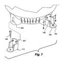
- FIGS. 7-9 depict the footings 114 and their connection to the housing 102 in more detail.
- the lower housing portion 120 may include slots 300 for joining each footing 114 to the housing 102 .
- the slots 300 may be generally oval or any other desired shape.
- Each footing may include one or more upper holes 302 for receiving fasteners (not shown) to join the footing 114 to the housing 102 .
- the fasteners may be self-tapping screws, or holes (not shown) may be pre-drilled or formed in the housing 102 for receiving the fasteners.
- a footing wall 304 may extend rearward from a footing 114 .
- the footing wall 304 may end in a head 306 for engagement with wings 308 extending from the housing 102 .
- the head 306 may be arrowhead shaped or any other suitable shape for engagement with the wings 308 .
- the wings 308 may be sufficiently flexible to move away from each other as the prong 304 is inserted through the housing slot 300 . Once the head 306 clears the inner edge of the wings 308 , the wings 308 move inward such that a bearing surfaces of the head 306 engage the inward edges of the wings 308 . Such engagement between the head 306 and the wings 308 resists removal of the footing wall 304 from the housing slot 300 .
- the footing wall 304 may take the form of a pair of prongs that extend rearwardly from a footing 114 .
- Each prong may end in a tab for engagement with the housing 102 .
- the prongs may be biased slightly outward from each other to engage an inner edge of the housing 102 when inserted through the housing slots 300 .
- the prongs may be sufficiently flexible to move towards each other as they are inserted through the housing slot 300 . Once the tabs on the prongs clear the inner surface of the inner edge of the housing slot 300 , the bias in the prongs moves them outward such that the tabs engage the inner edge of the housing 102 proximate the slot 300 . Such engagement resists removal of the footing 114 from the housing 102 .
- the footings 114 may be joined to the housing 102 using heat or sonic welding, adhesives, other joining methods, or some combination of methods. Regardless of the method, or the combination of methods, used to join the footings 114 to the housing 102 , the connection between the footings 114 and the housing 102 may be designed to at least transfer minimum predetermined forces that may be imposed upon the pool filter 100 to a support surface through the footings 114 to limit or prevent overturning or other undesired movement of the housing 102 from its rest position.
- the components of the pool filter described herein may be composed of any suitable material, including, but not limited to, plastic (e.g., PVC), metal, alloy, rubber, and so on. Any of the components may be formed from a single part, or may be formed from multiple parts joined together to create the component.
- plastic e.g., PVC
- metal e.g., metal, alloy, rubber, and so on.
- Any of the components may be formed from a single part, or may be formed from multiple parts joined together to create the component.
Landscapes
- Chemical & Material Sciences (AREA)
- Chemical Kinetics & Catalysis (AREA)
- Filtering Of Dispersed Particles In Gases (AREA)
Abstract
Description
Claims (12)
Priority Applications (6)
| Application Number | Priority Date | Filing Date | Title |
|---|---|---|---|
| US11/967,664 US7815796B2 (en) | 2007-03-23 | 2007-12-31 | Pool filter |
| US12/053,446 US7794591B2 (en) | 2007-03-23 | 2008-03-21 | Pool filter |
| AU2008201362A AU2008201362B2 (en) | 2007-03-23 | 2008-03-25 | Pool filter |
| CA2627178A CA2627178C (en) | 2007-03-23 | 2008-03-25 | Pool filter |
| US12/880,601 US8137545B2 (en) | 2007-03-23 | 2010-09-13 | Pool filter |
| US12/906,843 US20110089094A1 (en) | 2007-03-23 | 2010-10-18 | Pool Filter |
Applications Claiming Priority (2)
| Application Number | Priority Date | Filing Date | Title |
|---|---|---|---|
| US89679707P | 2007-03-23 | 2007-03-23 | |
| US11/967,664 US7815796B2 (en) | 2007-03-23 | 2007-12-31 | Pool filter |
Related Child Applications (2)
| Application Number | Title | Priority Date | Filing Date |
|---|---|---|---|
| US12/053,446 Continuation-In-Part US7794591B2 (en) | 2007-03-23 | 2008-03-21 | Pool filter |
| US12/906,843 Division US20110089094A1 (en) | 2007-03-23 | 2010-10-18 | Pool Filter |
Publications (2)
| Publication Number | Publication Date |
|---|---|
| US20080230454A1 US20080230454A1 (en) | 2008-09-25 |
| US7815796B2 true US7815796B2 (en) | 2010-10-19 |
Family
ID=39773640
Family Applications (2)
| Application Number | Title | Priority Date | Filing Date |
|---|---|---|---|
| US11/967,664 Active 2028-03-28 US7815796B2 (en) | 2007-03-23 | 2007-12-31 | Pool filter |
| US12/906,843 Abandoned US20110089094A1 (en) | 2007-03-23 | 2010-10-18 | Pool Filter |
Family Applications After (1)
| Application Number | Title | Priority Date | Filing Date |
|---|---|---|---|
| US12/906,843 Abandoned US20110089094A1 (en) | 2007-03-23 | 2010-10-18 | Pool Filter |
Country Status (1)
| Country | Link |
|---|---|
| US (2) | US7815796B2 (en) |
Cited By (9)
| Publication number | Priority date | Publication date | Assignee | Title |
|---|---|---|---|---|
| US7951293B2 (en) | 2007-10-05 | 2011-05-31 | Zodiac Pool Systems, Inc. | Methods and apparatus for a pool treatment and water system |
| USD655379S1 (en) * | 2010-11-12 | 2012-03-06 | Poolrite Research Pty Ltd | Swimming pool filtration unit |
| US8137545B2 (en) | 2007-03-23 | 2012-03-20 | Zodiac Pool Systems, Inc. | Pool filter |
| US8516661B2 (en) | 2009-04-29 | 2013-08-27 | Zodiac Pool Systems, Inc. | Retainer band for use in fluid-handling vessels |
| US9194493B2 (en) | 2011-09-30 | 2015-11-24 | Pentair Water Pool And Spa, Inc. | Filter clamp lock |
| US9816282B2 (en) * | 2013-08-16 | 2017-11-14 | Robert Stanley Chick | Self cleaning swimming pool filter |
| US10385578B2 (en) * | 2017-12-04 | 2019-08-20 | Montasser M. Elsawi | Polyvinyl chloride conduit for backwashing pool filters |
| US10767770B2 (en) | 2017-02-28 | 2020-09-08 | Culligan International Company | Control valve assembly for fluid treatment apparatus |
| US11331616B2 (en) * | 2020-09-25 | 2022-05-17 | Mark Henderson | Pool filter assembly |
Families Citing this family (4)
| Publication number | Priority date | Publication date | Assignee | Title |
|---|---|---|---|---|
| US8262906B2 (en) * | 2006-11-10 | 2012-09-11 | Davbroz Pty Ltd. | Flow selection device for use with pools and the like |
| US7815796B2 (en) | 2007-03-23 | 2010-10-19 | Zodiac Pool Systems, Inc. | Pool filter |
| US8318010B2 (en) * | 2009-02-02 | 2012-11-27 | Yukon E Daniel | Quick disconnect liquid chromatograph columns |
| US7901574B2 (en) * | 2009-02-02 | 2011-03-08 | E. Daniel Yukon | Quick disconnect liquid chromatograph columns |
Citations (107)
| Publication number | Priority date | Publication date | Assignee | Title |
|---|---|---|---|---|
| US179698A (en) | 1876-07-11 | Improvement in combination unions for wrought-iron pipes | ||
| US432248A (en) | 1890-07-15 | Gustave o | ||
| US797152A (en) | 1905-04-01 | 1905-08-15 | Wilder R Sheckler | Combined union, reducer, and expansion-joint. |
| US1394631A (en) | 1919-09-08 | 1921-10-25 | Us Slicing Machine Co | Adjustable support |
| US1528449A (en) | 1922-07-26 | 1925-03-03 | Evinrude Motor Co | Portable pump and motor unit |
| US1748898A (en) * | 1927-08-23 | 1930-02-25 | Peebles James | Apparatus for cleaning sand filter beds and the like |
| US1820020A (en) | 1928-11-26 | 1931-08-25 | Westinghouse Air Brake Co | Pipe coupling |
| US2284787A (en) | 1938-04-08 | 1942-06-02 | Winkler Jack | Filter |
| US2315681A (en) | 1940-05-31 | 1943-04-06 | Edwin C Weisgerber | Filter |
| US2335109A (en) | 1942-06-02 | 1943-11-23 | F E Myers & Bro Co | Combination centrifugal ejector pump |
| US2615397A (en) | 1949-04-07 | 1952-10-28 | F E Meyers & Bro Co | Pumping apparatus |
| US2662988A (en) | 1948-07-15 | 1953-12-15 | Gen Electric | Base for motors |
| US2882828A (en) | 1956-09-21 | 1959-04-21 | John N Hinckley | Pumps having rotors and swinging arms |
| US3178024A (en) | 1960-06-13 | 1965-04-13 | Jacuzzi Bros Inc | Filter system assembly |
| US3420376A (en) | 1966-02-07 | 1969-01-07 | George L Smith | Filter apparatus for swimming pool water |
| US3429443A (en) | 1966-07-08 | 1969-02-25 | Howard B Stern | Fluid velocity deceleration device |
| US3493116A (en) | 1969-02-10 | 1970-02-03 | Swimrite Mfg Co Inc | Swimming pool filter |
| US3519135A (en) | 1968-04-24 | 1970-07-07 | Marc Lerner | Filter tank |
| US3581895A (en) | 1969-02-28 | 1971-06-01 | Herbert H Howard | Automatic backwashing filter system for swimming pools |
| US3625365A (en) | 1969-06-25 | 1971-12-07 | Jacuzzi Bros Inc | Underdrain assembly for pool-type filter |
| US3664768A (en) | 1970-03-10 | 1972-05-23 | William T Mays | Fluid transformer |
| US3707233A (en) | 1970-10-13 | 1972-12-26 | Marc Lerner | Filter tank and mounting adaptor for multiport valves |
| US3747768A (en) | 1972-05-09 | 1973-07-24 | Wilkes Pool Corp | Filter unit and filtrate collector therefor |
| US3767050A (en) | 1972-01-04 | 1973-10-23 | Coleco Ind Inc | Filtration system for liquids |
| US3779387A (en) | 1971-10-20 | 1973-12-18 | Ocean Protein Corp | Filter |
| US3795320A (en) | 1972-03-06 | 1974-03-05 | Swimquip Inc | Filter element construction |
| US3828932A (en) | 1973-04-18 | 1974-08-13 | Coleco Ind Inc | Rotary swimming pool valve |
| US3834537A (en) | 1972-11-09 | 1974-09-10 | Purex Corp Ltd | High throughput filter having multiposition valve |
| GB1372014A (en) | 1972-12-29 | 1974-10-30 | Harms J F | Cartridge filter apparatus |
| US3911068A (en) | 1973-07-02 | 1975-10-07 | Jock Hamilton | Pool chlorination diffuser |
| US3929151A (en) | 1974-03-06 | 1975-12-30 | Harry S Rubin | Mixing apparatus |
| US3957644A (en) | 1973-01-22 | 1976-05-18 | Lawrence Aldean Edmonson | In-line filtering device |
| US3988244A (en) | 1975-06-30 | 1976-10-26 | Sta-Rite Industries, Inc. | Cartridge filter |
| US4003835A (en) | 1975-08-18 | 1977-01-18 | Johnson Harley D | Fittings |
| US4043917A (en) | 1976-04-01 | 1977-08-23 | Weil-Mclain Company, Inc. | Liquid filter apparatus |
| US4105555A (en) | 1976-12-06 | 1978-08-08 | Tolo, Incorporated | Multi-port valve |
| US4127485A (en) | 1977-07-05 | 1978-11-28 | Baker William H | Vacuum filter for swimming pools |
| US4134836A (en) | 1976-06-02 | 1979-01-16 | Wylain, Inc. | Filtering system for swimming pools or the like |
| US4169793A (en) | 1977-07-11 | 1979-10-02 | Tolo, Incorporated | Tank drain assembly for swimming pool filters |
| US4283281A (en) | 1979-10-29 | 1981-08-11 | Textile Industries, Inc. | High pressure filter vessel |
| US4537681A (en) | 1983-07-11 | 1985-08-27 | Sta-Rite Industries, Inc. | Cartridge filter end cap |
| US4602463A (en) | 1984-10-03 | 1986-07-29 | A. O. Smith Harvestore Products, Inc. | Tank construction having a floor formed of interconnected panels |
| US4627118A (en) * | 1984-05-04 | 1986-12-09 | Baker William H | Vacuum filter for swimming pools controlling water recirculation capacity to accommodate varying gutter flow |
| US4657673A (en) | 1985-11-13 | 1987-04-14 | Emerich Kessler | Dual filtering system for swimming pools |
| US4704202A (en) * | 1985-08-19 | 1987-11-03 | Victor Marquez | Water filtering system |
| US4712812A (en) | 1986-09-02 | 1987-12-15 | Weir Iii Joseph W | Universal fittings |
| US4798670A (en) | 1987-10-07 | 1989-01-17 | Hayward Industries, Inc. | Skimmer vacuum filter apparatus |
| US4810170A (en) | 1988-02-04 | 1989-03-07 | Ide Russell D | Jet pump |
| US4822077A (en) | 1988-09-26 | 1989-04-18 | Urdan Industries (Usa) Inc. | Pipe coupling reducing insert |
| US4869817A (en) | 1982-04-05 | 1989-09-26 | Hydrotech Chemical Corporation | Backwash valve lever control system |
| US4894149A (en) | 1988-09-16 | 1990-01-16 | Block Steven J | Biological filtration device |
| US4923601A (en) | 1987-09-18 | 1990-05-08 | Mordeki Drori | Filter system having multiple filter elements and backflushing assemblies |
| US4924069A (en) | 1987-11-19 | 1990-05-08 | Teledyne Industries, Inc. | Hot water supply for tubs |
| US4931183A (en) * | 1988-06-24 | 1990-06-05 | Klein Hans U | Process and apparatus for the biological purification of water |
| US4964609A (en) | 1989-06-14 | 1990-10-23 | Tecumseh Products Company | Compressor mounting apparatus |
| US4997558A (en) | 1988-07-01 | 1991-03-05 | Baker William H | Suction control filter system for swimming pools |
| US5000488A (en) | 1989-10-13 | 1991-03-19 | Albrecht David E | Adapter fittings and connectors |
| USD316741S (en) | 1990-01-19 | 1991-05-07 | Omni Corporation | Water filter |
| US5068033A (en) | 1990-05-10 | 1991-11-26 | Hayward Industries, Inc. | Underdrain assembly with pivotally-mounted and lockable laterals |
| US5087357A (en) | 1990-09-07 | 1992-02-11 | Villa Aquilino L | Aquarium filter apparatus |
| US5188727A (en) | 1990-07-18 | 1993-02-23 | Omni Corporation | Water filter unit |
| US5190651A (en) | 1991-06-24 | 1993-03-02 | Sta-Rite Industries, Inc. | Filter cartridge |
| US5222525A (en) | 1992-07-15 | 1993-06-29 | Coppus Engineering Corp. | Plastic diffuser |
| US5240593A (en) | 1991-02-05 | 1993-08-31 | Moredock James G | Apparatus for the purification of fluids |
| USD342986S (en) | 1992-01-31 | 1994-01-04 | Omni Corporation | Cover for a faucet mounted water filter |
| US5306121A (en) | 1993-04-23 | 1994-04-26 | Carrier Corporation | Compressor tiered mounting arrangement |
| US5375887A (en) | 1993-06-21 | 1994-12-27 | Johnson; Dwight N. | Plumbing hookup kit |
| US5409606A (en) | 1993-05-04 | 1995-04-25 | Sta-Rite Industries, Inc. | Filter apparatus |
| US5505847A (en) * | 1994-06-28 | 1996-04-09 | Cac Corporation | Water circulation system for a multiple mineral bath |
| US5524860A (en) | 1994-09-29 | 1996-06-11 | Ives; Lewis | Universal mounting bracket and method |
| US5584998A (en) | 1996-01-25 | 1996-12-17 | H-Tech, Inc. | Self-adjusting filter diffuser and method for assembling same in a filter housing |
| US5587074A (en) | 1995-02-17 | 1996-12-24 | H-Tech, Inc. | Fluid filter with enhanced backflush flow |
| US5653831A (en) | 1995-10-17 | 1997-08-05 | Sta-Rite Industries, Inc. | Method and apparatus for making a filter module |
| US5656159A (en) | 1996-04-12 | 1997-08-12 | Sta-Rite Industries, Inc. | Filter cartridge with integral bactericide |
| US5687994A (en) | 1994-07-15 | 1997-11-18 | Hansen; Albert Frederick | Pipe coupling |
| US5762785A (en) | 1997-05-29 | 1998-06-09 | Aplister, S.A. | Swimming pool filter |
| US5882515A (en) | 1996-03-01 | 1999-03-16 | Hydro-Flow Filtration Systems, Inc. | Inline filter having swivel fitting |
| US5942109A (en) | 1996-12-05 | 1999-08-24 | Oase-Pumpen Wuebker Soehne Gmbh & Co. | Apparatus for the treatment of liquids |
| US5989419A (en) * | 1998-03-02 | 1999-11-23 | Dudley; David E. | Spinner for cleaning cartridge-type water filters |
| US6029942A (en) | 1998-03-24 | 2000-02-29 | Carrier Corporation | Simplified compressor mount with self forming grommet |
| US6036853A (en) | 1998-04-16 | 2000-03-14 | Medtronic, Inc. | Articulated filter core element |
| US6156213A (en) * | 1998-03-02 | 2000-12-05 | Dudley; David E. | Embedded spin-clean cartridge-type water filters |
| US6258266B1 (en) | 1999-04-21 | 2001-07-10 | Sta-Rite Industries, Inc. | Faucet mount water filtration device |
| US6287466B1 (en) | 2000-08-11 | 2001-09-11 | Ihassan F. Yassin | Swimming pool water inlet pool chlorinator |
| US6345558B1 (en) | 2000-06-29 | 2002-02-12 | Toney Hugh Wilson | Gear pliers apparatus and method of use |
| US6450782B1 (en) | 2000-05-24 | 2002-09-17 | Wood Group Esp, Inc. | Pump-motor assembly having a motor mount |
| US6554939B1 (en) | 2000-10-10 | 2003-04-29 | Pentair Pool Products, Inc. | Container and method of forming the container |
| US6582613B2 (en) | 2001-08-16 | 2003-06-24 | Mooneyham Phillip D. | Engine coolant filter apparatus and method |
| US6605211B1 (en) | 2000-10-06 | 2003-08-12 | Jacuzzi Leisure Products | One-piece underdrain for swimming pool filters |
| US20040057845A1 (en) | 2002-09-23 | 2004-03-25 | Skinner Robin G. | Compressor mounting bracket and method of making |
| US6797164B2 (en) | 2001-11-21 | 2004-09-28 | A. H. Equipment Corporation | Filtering system for a pool or spa |
| US20050002800A1 (en) | 2003-06-27 | 2005-01-06 | Kazuya Kimura | Device having a pulsation reducing structure, a passage forming body and compressor |
| US6874641B2 (en) | 2003-04-09 | 2005-04-05 | Laars, Inc. | Hydrodynamic bearing |
| US20050158185A1 (en) | 2004-01-20 | 2005-07-21 | Herrick Todd W. | Compressor assemblies with improved mounting support and method of mounting such compressor assemblies |
| US7022230B2 (en) | 2000-06-21 | 2006-04-04 | Tohzai Electric Co. Ltd | Filtration device |
| US20060124527A1 (en) | 2004-09-20 | 2006-06-15 | Pentair Water Pool And Spa, Inc. | Filter devices including a porous body |
| US7081200B2 (en) | 2002-07-25 | 2006-07-25 | Sacopa, S.A.U. | Swimming pool filter |
| US7093721B2 (en) | 2003-09-03 | 2006-08-22 | Delaware Corporation Formation, Inc. | Filter assembly with sealed, magnetically coupled cleaning head actuator |
| US7097766B2 (en) | 2003-05-30 | 2006-08-29 | Griswold Controls | Sand filter with rotating vanes |
| US20070045163A1 (en) * | 2005-08-30 | 2007-03-01 | Meincke Jonathan E | Canister filter for swimming pool |
| US20070056903A1 (en) | 2005-09-12 | 2007-03-15 | Ron James | Filtration system |
| US7207604B2 (en) | 2004-08-11 | 2007-04-24 | Pentair Pool Products, Inc. | Snap-fit connection for pool filtration systems |
| US20070163929A1 (en) | 2004-08-26 | 2007-07-19 | Pentair Water Pool And Spa, Inc. | Filter loading |
| US20070227959A1 (en) | 2006-03-31 | 2007-10-04 | Sinur Richard R | Filter cartridges and methods |
| US7294262B2 (en) | 2003-08-27 | 2007-11-13 | Sta-Rite Industries, Llc | Modular fluid treatment apparatus |
| US20080230455A1 (en) | 2007-03-23 | 2008-09-25 | Nibler David B | Pool filter |
| US20080230454A1 (en) | 2007-03-23 | 2008-09-25 | Nibler David B | Pool filter |
Family Cites Families (5)
| Publication number | Priority date | Publication date | Assignee | Title |
|---|---|---|---|---|
| US3091339A (en) * | 1959-10-19 | 1963-05-28 | Maria V Marra | Food cleaner type strainer pan |
| US4250540A (en) * | 1979-08-23 | 1981-02-10 | Mcgraw-Edison Co. | Mounting arrangement for recessed light fixture housing |
| US4390425A (en) * | 1982-03-19 | 1983-06-28 | Tafara Peter T | High pressure liquid filter vessel |
| US4769052A (en) * | 1986-08-21 | 1988-09-06 | Cuno Incorporated | Compact filter assembly |
| US5320752A (en) * | 1992-11-03 | 1994-06-14 | Clack Corporation | Water purification system employing modular flat filter assembly |
-
2007
- 2007-12-31 US US11/967,664 patent/US7815796B2/en active Active
-
2010
- 2010-10-18 US US12/906,843 patent/US20110089094A1/en not_active Abandoned
Patent Citations (111)
| Publication number | Priority date | Publication date | Assignee | Title |
|---|---|---|---|---|
| US179698A (en) | 1876-07-11 | Improvement in combination unions for wrought-iron pipes | ||
| US432248A (en) | 1890-07-15 | Gustave o | ||
| US797152A (en) | 1905-04-01 | 1905-08-15 | Wilder R Sheckler | Combined union, reducer, and expansion-joint. |
| US1394631A (en) | 1919-09-08 | 1921-10-25 | Us Slicing Machine Co | Adjustable support |
| US1528449A (en) | 1922-07-26 | 1925-03-03 | Evinrude Motor Co | Portable pump and motor unit |
| US1748898A (en) * | 1927-08-23 | 1930-02-25 | Peebles James | Apparatus for cleaning sand filter beds and the like |
| US1820020A (en) | 1928-11-26 | 1931-08-25 | Westinghouse Air Brake Co | Pipe coupling |
| US2284787A (en) | 1938-04-08 | 1942-06-02 | Winkler Jack | Filter |
| US2315681A (en) | 1940-05-31 | 1943-04-06 | Edwin C Weisgerber | Filter |
| US2335109A (en) | 1942-06-02 | 1943-11-23 | F E Myers & Bro Co | Combination centrifugal ejector pump |
| US2662988A (en) | 1948-07-15 | 1953-12-15 | Gen Electric | Base for motors |
| US2615397A (en) | 1949-04-07 | 1952-10-28 | F E Meyers & Bro Co | Pumping apparatus |
| US2882828A (en) | 1956-09-21 | 1959-04-21 | John N Hinckley | Pumps having rotors and swinging arms |
| US3178024A (en) | 1960-06-13 | 1965-04-13 | Jacuzzi Bros Inc | Filter system assembly |
| US3420376A (en) | 1966-02-07 | 1969-01-07 | George L Smith | Filter apparatus for swimming pool water |
| US3429443A (en) | 1966-07-08 | 1969-02-25 | Howard B Stern | Fluid velocity deceleration device |
| US3519135A (en) | 1968-04-24 | 1970-07-07 | Marc Lerner | Filter tank |
| US3493116A (en) | 1969-02-10 | 1970-02-03 | Swimrite Mfg Co Inc | Swimming pool filter |
| US3581895A (en) | 1969-02-28 | 1971-06-01 | Herbert H Howard | Automatic backwashing filter system for swimming pools |
| US3625365A (en) | 1969-06-25 | 1971-12-07 | Jacuzzi Bros Inc | Underdrain assembly for pool-type filter |
| US3664768A (en) | 1970-03-10 | 1972-05-23 | William T Mays | Fluid transformer |
| US3707233A (en) | 1970-10-13 | 1972-12-26 | Marc Lerner | Filter tank and mounting adaptor for multiport valves |
| US3779387A (en) | 1971-10-20 | 1973-12-18 | Ocean Protein Corp | Filter |
| US3767050A (en) | 1972-01-04 | 1973-10-23 | Coleco Ind Inc | Filtration system for liquids |
| US3795320A (en) | 1972-03-06 | 1974-03-05 | Swimquip Inc | Filter element construction |
| US3747768A (en) | 1972-05-09 | 1973-07-24 | Wilkes Pool Corp | Filter unit and filtrate collector therefor |
| US3834537A (en) | 1972-11-09 | 1974-09-10 | Purex Corp Ltd | High throughput filter having multiposition valve |
| GB1372014A (en) | 1972-12-29 | 1974-10-30 | Harms J F | Cartridge filter apparatus |
| US3957644A (en) | 1973-01-22 | 1976-05-18 | Lawrence Aldean Edmonson | In-line filtering device |
| US3828932A (en) | 1973-04-18 | 1974-08-13 | Coleco Ind Inc | Rotary swimming pool valve |
| US3911068A (en) | 1973-07-02 | 1975-10-07 | Jock Hamilton | Pool chlorination diffuser |
| US3929151A (en) | 1974-03-06 | 1975-12-30 | Harry S Rubin | Mixing apparatus |
| US3988244A (en) | 1975-06-30 | 1976-10-26 | Sta-Rite Industries, Inc. | Cartridge filter |
| US4003835A (en) | 1975-08-18 | 1977-01-18 | Johnson Harley D | Fittings |
| US4043917A (en) | 1976-04-01 | 1977-08-23 | Weil-Mclain Company, Inc. | Liquid filter apparatus |
| US4134836A (en) | 1976-06-02 | 1979-01-16 | Wylain, Inc. | Filtering system for swimming pools or the like |
| US4105555A (en) | 1976-12-06 | 1978-08-08 | Tolo, Incorporated | Multi-port valve |
| US4127485A (en) | 1977-07-05 | 1978-11-28 | Baker William H | Vacuum filter for swimming pools |
| US4169793A (en) | 1977-07-11 | 1979-10-02 | Tolo, Incorporated | Tank drain assembly for swimming pool filters |
| US4283281A (en) | 1979-10-29 | 1981-08-11 | Textile Industries, Inc. | High pressure filter vessel |
| US4869817A (en) | 1982-04-05 | 1989-09-26 | Hydrotech Chemical Corporation | Backwash valve lever control system |
| US4537681A (en) | 1983-07-11 | 1985-08-27 | Sta-Rite Industries, Inc. | Cartridge filter end cap |
| US4627118A (en) * | 1984-05-04 | 1986-12-09 | Baker William H | Vacuum filter for swimming pools controlling water recirculation capacity to accommodate varying gutter flow |
| US4602463A (en) | 1984-10-03 | 1986-07-29 | A. O. Smith Harvestore Products, Inc. | Tank construction having a floor formed of interconnected panels |
| US4704202A (en) * | 1985-08-19 | 1987-11-03 | Victor Marquez | Water filtering system |
| US4657673A (en) | 1985-11-13 | 1987-04-14 | Emerich Kessler | Dual filtering system for swimming pools |
| US4712812A (en) | 1986-09-02 | 1987-12-15 | Weir Iii Joseph W | Universal fittings |
| US5328604A (en) | 1987-09-18 | 1994-07-12 | Mordeki Drori | Filter system having bottom manifold and means for causing filter rotation |
| US5112481A (en) | 1987-09-18 | 1992-05-12 | Mordeki Drori | Filter system having multiple filter elements and backflushing assemblies |
| US4923601A (en) | 1987-09-18 | 1990-05-08 | Mordeki Drori | Filter system having multiple filter elements and backflushing assemblies |
| US4798670A (en) | 1987-10-07 | 1989-01-17 | Hayward Industries, Inc. | Skimmer vacuum filter apparatus |
| US4924069A (en) | 1987-11-19 | 1990-05-08 | Teledyne Industries, Inc. | Hot water supply for tubs |
| US4810170A (en) | 1988-02-04 | 1989-03-07 | Ide Russell D | Jet pump |
| US4931183A (en) * | 1988-06-24 | 1990-06-05 | Klein Hans U | Process and apparatus for the biological purification of water |
| US4997558A (en) | 1988-07-01 | 1991-03-05 | Baker William H | Suction control filter system for swimming pools |
| US4894149A (en) | 1988-09-16 | 1990-01-16 | Block Steven J | Biological filtration device |
| US4822077A (en) | 1988-09-26 | 1989-04-18 | Urdan Industries (Usa) Inc. | Pipe coupling reducing insert |
| US4964609A (en) | 1989-06-14 | 1990-10-23 | Tecumseh Products Company | Compressor mounting apparatus |
| US5000488A (en) | 1989-10-13 | 1991-03-19 | Albrecht David E | Adapter fittings and connectors |
| USD316741S (en) | 1990-01-19 | 1991-05-07 | Omni Corporation | Water filter |
| US5068033A (en) | 1990-05-10 | 1991-11-26 | Hayward Industries, Inc. | Underdrain assembly with pivotally-mounted and lockable laterals |
| US5188727A (en) | 1990-07-18 | 1993-02-23 | Omni Corporation | Water filter unit |
| US5087357A (en) | 1990-09-07 | 1992-02-11 | Villa Aquilino L | Aquarium filter apparatus |
| US5240593A (en) | 1991-02-05 | 1993-08-31 | Moredock James G | Apparatus for the purification of fluids |
| US5190651A (en) | 1991-06-24 | 1993-03-02 | Sta-Rite Industries, Inc. | Filter cartridge |
| USD342986S (en) | 1992-01-31 | 1994-01-04 | Omni Corporation | Cover for a faucet mounted water filter |
| US5222525A (en) | 1992-07-15 | 1993-06-29 | Coppus Engineering Corp. | Plastic diffuser |
| US5306121A (en) | 1993-04-23 | 1994-04-26 | Carrier Corporation | Compressor tiered mounting arrangement |
| US5409606A (en) | 1993-05-04 | 1995-04-25 | Sta-Rite Industries, Inc. | Filter apparatus |
| US5375887A (en) | 1993-06-21 | 1994-12-27 | Johnson; Dwight N. | Plumbing hookup kit |
| US5505847A (en) * | 1994-06-28 | 1996-04-09 | Cac Corporation | Water circulation system for a multiple mineral bath |
| US5687994A (en) | 1994-07-15 | 1997-11-18 | Hansen; Albert Frederick | Pipe coupling |
| US5524860A (en) | 1994-09-29 | 1996-06-11 | Ives; Lewis | Universal mounting bracket and method |
| US5587074A (en) | 1995-02-17 | 1996-12-24 | H-Tech, Inc. | Fluid filter with enhanced backflush flow |
| US5653831A (en) | 1995-10-17 | 1997-08-05 | Sta-Rite Industries, Inc. | Method and apparatus for making a filter module |
| US5753071A (en) | 1995-10-17 | 1998-05-19 | Sta-Rite Industries, Inc. | Apparatus for making a filter module |
| US5584998A (en) | 1996-01-25 | 1996-12-17 | H-Tech, Inc. | Self-adjusting filter diffuser and method for assembling same in a filter housing |
| US5882515A (en) | 1996-03-01 | 1999-03-16 | Hydro-Flow Filtration Systems, Inc. | Inline filter having swivel fitting |
| US6280619B1 (en) | 1996-03-01 | 2001-08-28 | Sta-Rite Industries | Inline filter having swivel fitting |
| US5656159A (en) | 1996-04-12 | 1997-08-12 | Sta-Rite Industries, Inc. | Filter cartridge with integral bactericide |
| US5942109A (en) | 1996-12-05 | 1999-08-24 | Oase-Pumpen Wuebker Soehne Gmbh & Co. | Apparatus for the treatment of liquids |
| US5762785A (en) | 1997-05-29 | 1998-06-09 | Aplister, S.A. | Swimming pool filter |
| US5989419A (en) * | 1998-03-02 | 1999-11-23 | Dudley; David E. | Spinner for cleaning cartridge-type water filters |
| US6156213A (en) * | 1998-03-02 | 2000-12-05 | Dudley; David E. | Embedded spin-clean cartridge-type water filters |
| US6029942A (en) | 1998-03-24 | 2000-02-29 | Carrier Corporation | Simplified compressor mount with self forming grommet |
| US6036853A (en) | 1998-04-16 | 2000-03-14 | Medtronic, Inc. | Articulated filter core element |
| US6258266B1 (en) | 1999-04-21 | 2001-07-10 | Sta-Rite Industries, Inc. | Faucet mount water filtration device |
| US6450782B1 (en) | 2000-05-24 | 2002-09-17 | Wood Group Esp, Inc. | Pump-motor assembly having a motor mount |
| US7022230B2 (en) | 2000-06-21 | 2006-04-04 | Tohzai Electric Co. Ltd | Filtration device |
| US6345558B1 (en) | 2000-06-29 | 2002-02-12 | Toney Hugh Wilson | Gear pliers apparatus and method of use |
| US6287466B1 (en) | 2000-08-11 | 2001-09-11 | Ihassan F. Yassin | Swimming pool water inlet pool chlorinator |
| US6605211B1 (en) | 2000-10-06 | 2003-08-12 | Jacuzzi Leisure Products | One-piece underdrain for swimming pool filters |
| US6554939B1 (en) | 2000-10-10 | 2003-04-29 | Pentair Pool Products, Inc. | Container and method of forming the container |
| US6582613B2 (en) | 2001-08-16 | 2003-06-24 | Mooneyham Phillip D. | Engine coolant filter apparatus and method |
| US6797164B2 (en) | 2001-11-21 | 2004-09-28 | A. H. Equipment Corporation | Filtering system for a pool or spa |
| US7081200B2 (en) | 2002-07-25 | 2006-07-25 | Sacopa, S.A.U. | Swimming pool filter |
| US20040057845A1 (en) | 2002-09-23 | 2004-03-25 | Skinner Robin G. | Compressor mounting bracket and method of making |
| US6874641B2 (en) | 2003-04-09 | 2005-04-05 | Laars, Inc. | Hydrodynamic bearing |
| US7097766B2 (en) | 2003-05-30 | 2006-08-29 | Griswold Controls | Sand filter with rotating vanes |
| US20050002800A1 (en) | 2003-06-27 | 2005-01-06 | Kazuya Kimura | Device having a pulsation reducing structure, a passage forming body and compressor |
| US7294262B2 (en) | 2003-08-27 | 2007-11-13 | Sta-Rite Industries, Llc | Modular fluid treatment apparatus |
| US7093721B2 (en) | 2003-09-03 | 2006-08-22 | Delaware Corporation Formation, Inc. | Filter assembly with sealed, magnetically coupled cleaning head actuator |
| US20050158185A1 (en) | 2004-01-20 | 2005-07-21 | Herrick Todd W. | Compressor assemblies with improved mounting support and method of mounting such compressor assemblies |
| US7207604B2 (en) | 2004-08-11 | 2007-04-24 | Pentair Pool Products, Inc. | Snap-fit connection for pool filtration systems |
| US20070163929A1 (en) | 2004-08-26 | 2007-07-19 | Pentair Water Pool And Spa, Inc. | Filter loading |
| US20060124527A1 (en) | 2004-09-20 | 2006-06-15 | Pentair Water Pool And Spa, Inc. | Filter devices including a porous body |
| US20070045163A1 (en) * | 2005-08-30 | 2007-03-01 | Meincke Jonathan E | Canister filter for swimming pool |
| US20070056903A1 (en) | 2005-09-12 | 2007-03-15 | Ron James | Filtration system |
| US20070227959A1 (en) | 2006-03-31 | 2007-10-04 | Sinur Richard R | Filter cartridges and methods |
| US20080230455A1 (en) | 2007-03-23 | 2008-09-25 | Nibler David B | Pool filter |
| US20080230454A1 (en) | 2007-03-23 | 2008-09-25 | Nibler David B | Pool filter |
Non-Patent Citations (5)
| Title |
|---|
| Jandy 2007 Catalog, Filter Parts, Jandy Pool Products, Inc., pp. 31-41. |
| Jandy 2007 Catalog, Filters, Jandy Pool Products, Inc., pp. 23-30. |
| Jandy 2008 Catalog, Filter Parts, Jandy Pool Products, Inc., pp. 32-44. |
| Jandy 2008 Catalog, Filters, Jandy Pool Products, Inc., pp. 23-31. |
| Office Action dated Nov. 18, 2009, Australia Patent Application No. 2008201362, 3 pages. |
Cited By (17)
| Publication number | Priority date | Publication date | Assignee | Title |
|---|---|---|---|---|
| US8137545B2 (en) | 2007-03-23 | 2012-03-20 | Zodiac Pool Systems, Inc. | Pool filter |
| US8173011B2 (en) | 2007-10-05 | 2012-05-08 | Zodiac Pool Systems, Inc. | Methods and apparatus for a pool treatment and water system |
| US7951293B2 (en) | 2007-10-05 | 2011-05-31 | Zodiac Pool Systems, Inc. | Methods and apparatus for a pool treatment and water system |
| US8516661B2 (en) | 2009-04-29 | 2013-08-27 | Zodiac Pool Systems, Inc. | Retainer band for use in fluid-handling vessels |
| USD655379S1 (en) * | 2010-11-12 | 2012-03-06 | Poolrite Research Pty Ltd | Swimming pool filtration unit |
| US9194493B2 (en) | 2011-09-30 | 2015-11-24 | Pentair Water Pool And Spa, Inc. | Filter clamp lock |
| US10082164B2 (en) | 2011-09-30 | 2018-09-25 | Pentair Water Pool And Spa, Inc. | Filter clamp lock |
| US10563682B2 (en) | 2011-09-30 | 2020-02-18 | Pentair Water Pool And Spa, Inc. | Filter clamp lock |
| US10995781B2 (en) | 2011-09-30 | 2021-05-04 | Pentair Water Pool And Spa, Inc. | Filter clamp lock |
| US9816282B2 (en) * | 2013-08-16 | 2017-11-14 | Robert Stanley Chick | Self cleaning swimming pool filter |
| US11655903B2 (en) | 2017-02-28 | 2023-05-23 | Culligan International Company | Control valve assembly for fluid treatment apparatus |
| US10767770B2 (en) | 2017-02-28 | 2020-09-08 | Culligan International Company | Control valve assembly for fluid treatment apparatus |
| US10385578B2 (en) * | 2017-12-04 | 2019-08-20 | Montasser M. Elsawi | Polyvinyl chloride conduit for backwashing pool filters |
| US11136772B2 (en) | 2017-12-04 | 2021-10-05 | Montasser M. Elsawi | Swimming pool filtration system with means to spray backwash away from the system |
| US11331616B2 (en) * | 2020-09-25 | 2022-05-17 | Mark Henderson | Pool filter assembly |
| US20240238715A1 (en) * | 2020-09-25 | 2024-07-18 | Mark Henderson | Pool filter assembly |
| US12128344B2 (en) * | 2020-09-25 | 2024-10-29 | Mark Henderson | Pool filter assembly |
Also Published As
| Publication number | Publication date |
|---|---|
| US20110089094A1 (en) | 2011-04-21 |
| US20080230454A1 (en) | 2008-09-25 |
Similar Documents
| Publication | Publication Date | Title |
|---|---|---|
| US7794591B2 (en) | Pool filter | |
| US7815796B2 (en) | Pool filter | |
| US8459698B2 (en) | Riser cap and irrigation piping system using same | |
| US6217755B1 (en) | In-tank fluid filter with valve assembly | |
| EP0970477B1 (en) | Suction system with end supported internal core tube suction strainers | |
| US20130020246A1 (en) | Filter Vessel Assembly and Related Methods of Use | |
| US20160146399A1 (en) | Nozzle-type steam trap | |
| US20210137032A1 (en) | Irrigation filter system | |
| US7766262B2 (en) | Irrigation systems including flush valves, and methods for flushing debris from irrigation systems | |
| US6149703A (en) | Fuel system filtering apparatus | |
| CN110805779A (en) | An open pipeline anti-foreign body blocking device with blocking ability monitoring | |
| KR101233409B1 (en) | Expanded pipe and pipe joint | |
| JP2003512146A (en) | Filter element with riser | |
| CN219413921U (en) | Fluid dispenser assembly | |
| KR20220032983A (en) | Pipeline inspection and washing device | |
| KR100986260B1 (en) | Strainer unit | |
| TWI829026B (en) | filter | |
| KR200445623Y1 (en) | Strainer Integral Pipe Forming Ball Valve | |
| US20260034482A1 (en) | Y-Strainers and Related Methods | |
| KR20170115843A (en) | filtering device for irrigation | |
| JP2017223377A (en) | Temperature control device | |
| US9776122B2 (en) | High pressure compressed air/gas/steam filter | |
| CN219128556U (en) | Mounting structure of plastic filter element | |
| CN211543251U (en) | Fuel tank convenient to filter | |
| KR20250145960A (en) | End cap device for a ventilation pipe |
Legal Events
| Date | Code | Title | Description |
|---|---|---|---|
| AS | Assignment |
Owner name: JANDY POOL PRODUCTS, INC., CALIFORNIA Free format text: ASSIGNMENT OF ASSIGNORS INTEREST;ASSIGNORS:NIBLER, DAVID B.;TAN, RANDY;REEL/FRAME:020543/0196;SIGNING DATES FROM 20070925 TO 20071022 Owner name: JANDY POOL PRODUCTS, INC., CALIFORNIA Free format text: ASSIGNMENT OF ASSIGNORS INTEREST;ASSIGNORS:NIBLER, DAVID B.;TAN, RANDY;SIGNING DATES FROM 20070925 TO 20071022;REEL/FRAME:020543/0196 |
|
| AS | Assignment |
Owner name: ZODIAC POOL SYSTEMS, INC., CALIFORNIA Free format text: CHANGE OF NAME;ASSIGNOR:JANDY POOL PRODUCTS, INC.;REEL/FRAME:022408/0052 Effective date: 20080909 |
|
| AS | Assignment |
Owner name: ZODIAC POOL SYSTEMS, INC., CALIFORNIA Free format text: ASSIGNMENT OF ASSIGNORS INTEREST;ASSIGNOR:GUTAI, STEVE E.;REEL/FRAME:022522/0670 Effective date: 20090116 |
|
| FEPP | Fee payment procedure |
Free format text: PAYOR NUMBER ASSIGNED (ORIGINAL EVENT CODE: ASPN); ENTITY STATUS OF PATENT OWNER: LARGE ENTITY |
|
| STCF | Information on status: patent grant |
Free format text: PATENTED CASE |
|
| AS | Assignment |
Owner name: ING BANK N.V., UNITED KINGDOM Free format text: INTELLECTUAL PROPERTY SECURITY AGREEMENT;ASSIGNOR:ZODIAC POOL SYSTEMS, INC.;REEL/FRAME:029732/0429 Effective date: 20130131 |
|
| FPAY | Fee payment |
Year of fee payment: 4 |
|
| AS | Assignment |
Owner name: ZODIAC POOL SYSTEMS, INC., CALIFORNIA Free format text: RELEASE BY SECURED PARTY;ASSIGNOR:ING BANK N.V., LONDON BRANCH;REEL/FRAME:040935/0141 Effective date: 20161220 |
|
| AS | Assignment |
Owner name: BANK OF AMERICA, N.A., CALIFORNIA Free format text: ABL INTELLECTUAL PROPERTY SECURITY AGREEMENT;ASSIGNORS:COVER-POOLS INCORPORATED;ZODIAC POOL SYSTEMS, INC.;ZODIAC POOL SOLUTIONS NORTH AMERICA, INC.;REEL/FRAME:041357/0001 Effective date: 20161220 Owner name: CREDIT SUISSE AG, CAYMAN ISLANDS BRANCH, NEW YORK Free format text: SECOND LIEN INTELLECTUAL PROPERTY SECURITY AGREEMENT;ASSIGNORS:COVER-POOLS INCORPORATED;ZODIAC POOL SYSTEMS, INC.;ZODIAC POOL SOLUTIONS NORTH AMERICA, INC.;REEL/FRAME:041365/0640 Effective date: 20161220 Owner name: CREDIT SUISSE AG, CAYMAN ISLANDS BRANCH, NEW YORK Free format text: FIRST LIEN INTELLECTUAL PROPERTY SECURITY AGREEMENT;ASSIGNORS:COVER-POOLS INCORPORATED;ZODIAC POOL SYSTEMS, INC.;ZODIAC POOL SOLUTIONS NORTH AMERICA, INC.;REEL/FRAME:041368/0519 Effective date: 20161220 |
|
| MAFP | Maintenance fee payment |
Free format text: PAYMENT OF MAINTENANCE FEE, 8TH YEAR, LARGE ENTITY (ORIGINAL EVENT CODE: M1552) Year of fee payment: 8 |
|
| AS | Assignment |
Owner name: ZODIAC POOL SYSTEMS, INC, CALIFORNIA Free format text: CORRECTIVE ASSIGNMENT TO CORRECT THE INCORRECT NUMBER INADVERTENTLY INCLUDED, 9312583 SHOULD BE 8312583 AND ADD A NUMBER INADVERTENTLY EXCLUDED 6149049. PREVIOUSLY RECORDED ON REEL 040935 FRAME 0141. ASSIGNOR(S) HEREBY CONFIRMS THE RELEASE OF SECURITY INTEREST;ASSIGNOR:ING BANK N.V., LONDON BRANCH;REEL/FRAME:046422/0882 Effective date: 20161220 |
|
| AS | Assignment |
Owner name: ZODIAC POOL SYSTEMS LLC (FORMERLY KNOWN AS ZODIAC POOL SYSTEMS, INC.), CALIFORNIA Free format text: PATENT RELEASE (ABL);ASSIGNOR:BANK OF AMERICA, N.A.;REEL/FRAME:046492/0026 Effective date: 20180702 Owner name: ZODIAC POOL SOLUTIONS LLC (AS SUCCESSOR IN INTEREST TO ZODIAC POOL SOLUTIONS NORTH AMERICA, INC.), CALIFORNIA Free format text: PATENT RELEASE (ABL);ASSIGNOR:BANK OF AMERICA, N.A.;REEL/FRAME:046492/0026 Effective date: 20180702 Owner name: ZODIAC POOL SYSTEMS LLC (FORMERLY KNOWN AS ZODIAC POOL SYSTEMS, INC.), CALIFORNIA Free format text: PATENT RELEASE (SECOND LIEN);ASSIGNOR:CREDIT SUISSE AG, CAYMAN ISLANDS BRANCH;REEL/FRAME:046492/0037 Effective date: 20180702 Owner name: ZODIAC POOL SOLUTIONS LLC (AS SUCCESSOR IN INTEREST TO ZODIAC POOL SOLUTIONS NORTH AMERICA, INC.), CALIFORNIA Free format text: PATENT RELEASE (SECOND LIEN);ASSIGNOR:CREDIT SUISSE AG, CAYMAN ISLANDS BRANCH;REEL/FRAME:046492/0037 Effective date: 20180702 Owner name: ZODIAC POOL SOLUTIONS LLC (AS SUCCESSOR IN INTEREST TO ZODIAC POOL SOLUTIONS NORTH AMERICA, INC.), CALIFORNIA Free format text: PATENT RELEASE (FIRST LIEN);ASSIGNOR:CREDIT SUISSE AG, CAYMAN ISLANDS BRANCH;REEL/FRAME:047248/0655 Effective date: 20180702 Owner name: ZODIAC POOL SYSTEMS LLC (FORMERLY KNOWN AS ZODIAC POOL SYSTEMS, INC.), CALIFORNIA Free format text: PATENT RELEASE (FIRST LIEN);ASSIGNOR:CREDIT SUISSE AG, CAYMAN ISLANDS BRANCH;REEL/FRAME:047248/0655 Effective date: 20180702 Owner name: ZODIAC POOL SYSTEMS LLC (FORMERLY KNOWN AS ZODIAC Free format text: PATENT RELEASE (ABL);ASSIGNOR:BANK OF AMERICA, N.A.;REEL/FRAME:046492/0026 Effective date: 20180702 Owner name: ZODIAC POOL SYSTEMS LLC (FORMERLY KNOWN AS ZODIAC Free format text: PATENT RELEASE (SECOND LIEN);ASSIGNOR:CREDIT SUISSE AG, CAYMAN ISLANDS BRANCH;REEL/FRAME:046492/0037 Effective date: 20180702 Owner name: ZODIAC POOL SOLUTIONS LLC (AS SUCCESSOR IN INTERES Free format text: PATENT RELEASE (ABL);ASSIGNOR:BANK OF AMERICA, N.A.;REEL/FRAME:046492/0026 Effective date: 20180702 Owner name: ZODIAC POOL SOLUTIONS LLC (AS SUCCESSOR IN INTERES Free format text: PATENT RELEASE (SECOND LIEN);ASSIGNOR:CREDIT SUISSE AG, CAYMAN ISLANDS BRANCH;REEL/FRAME:046492/0037 Effective date: 20180702 Owner name: COVER-POOLS INCORPORATED, UTAH Free format text: PATENT RELEASE (ABL);ASSIGNOR:BANK OF AMERICA, N.A.;REEL/FRAME:046492/0026 Effective date: 20180702 Owner name: COVER-POOLS INCORPORATED, UTAH Free format text: PATENT RELEASE (SECOND LIEN);ASSIGNOR:CREDIT SUISSE AG, CAYMAN ISLANDS BRANCH;REEL/FRAME:046492/0037 Effective date: 20180702 Owner name: BANK OF AMERICA, N.A., CALIFORNIA Free format text: ABL INTELLECTUAL PROPERTY SECURITY AGREEMENT;ASSIGNORS:COVER-POOLS INCORPORATED;ZODIAC POOL SYSTEMS LLC;AQUA PRODUCTS, INC.;REEL/FRAME:046500/0291 Effective date: 20180702 Owner name: CREDIT SUISSE INTERNATIONAL, ENGLAND Free format text: SECURITY INTEREST;ASSIGNORS:COVER-POOLS INCORPORATED;ZODIAC POOL SYSTEMS LLC;AQUA PRODUCTS, INC.;REEL/FRAME:046622/0001 Effective date: 20180702 Owner name: ZODIAC POOL SYSTEMS LLC (FORMERLY KNOWN AS ZODIAC Free format text: PATENT RELEASE (FIRST LIEN);ASSIGNOR:CREDIT SUISSE AG, CAYMAN ISLANDS BRANCH;REEL/FRAME:047248/0655 Effective date: 20180702 Owner name: COVER-POOLS INCORPORATED, UTAH Free format text: PATENT RELEASE (FIRST LIEN);ASSIGNOR:CREDIT SUISSE AG, CAYMAN ISLANDS BRANCH;REEL/FRAME:047248/0655 Effective date: 20180702 Owner name: ZODIAC POOL SOLUTIONS LLC (AS SUCCESSOR IN INTERES Free format text: PATENT RELEASE (FIRST LIEN);ASSIGNOR:CREDIT SUISSE AG, CAYMAN ISLANDS BRANCH;REEL/FRAME:047248/0655 Effective date: 20180702 |
|
| AS | Assignment |
Owner name: ZODIAC POOL SYSTEMS LLC, DELAWARE Free format text: CHANGE OF NAME;ASSIGNOR:ZODIAC POOL SYSTEMS, INC.;REEL/FRAME:046634/0267 Effective date: 20170929 |
|
| AS | Assignment |
Owner name: HSBC BANK USA, N.A., NEW YORK Free format text: INTELLECTUAL PROPERTY SECURITY AGREEMENT ASSIGNMENT;ASSIGNOR:CREDIT SUISSE INTERNATIONAL;REEL/FRAME:058922/0901 Effective date: 20220127 |
|
| AS | Assignment |
Owner name: ZODIAC POOL SYSTEMS. INC., CALIFORNIA Free format text: RELEASE BY SECURED PARTY;ASSIGNOR:BANK OF AMERICA, N.A.;REEL/FRAME:058982/0912 Effective date: 20220127 Owner name: ZODIAC POOL SYSTEMS LLC, CALIFORNIA Free format text: RELEASE BY SECURED PARTY;ASSIGNOR:BANK OF AMERICA, N.A.;REEL/FRAME:058982/0912 Effective date: 20220127 Owner name: COVER-POOLS INCORPORATED, UTAH Free format text: RELEASE BY SECURED PARTY;ASSIGNOR:BANK OF AMERICA, N.A.;REEL/FRAME:058982/0912 Effective date: 20220127 Owner name: AQUA PRODUCTS, INC., NEW JERSEY Free format text: RELEASE BY SECURED PARTY;ASSIGNOR:BANK OF AMERICA, N.A.;REEL/FRAME:058982/0912 Effective date: 20220127 Owner name: AQUA PRODUCTS, INC., NEW JERSEY Free format text: RELEASE OF SECURITY INTEREST;ASSIGNOR:BANK OF AMERICA, N.A.;REEL/FRAME:058982/0912 Effective date: 20220127 Owner name: COVER-POOLS INCORPORATED, UTAH Free format text: RELEASE OF SECURITY INTEREST;ASSIGNOR:BANK OF AMERICA, N.A.;REEL/FRAME:058982/0912 Effective date: 20220127 Owner name: ZODIAC POOL SYSTEMS LLC, CALIFORNIA Free format text: RELEASE OF SECURITY INTEREST;ASSIGNOR:BANK OF AMERICA, N.A.;REEL/FRAME:058982/0912 Effective date: 20220127 Owner name: ZODIAC POOL SYSTEMS. INC., CALIFORNIA Free format text: RELEASE OF SECURITY INTEREST;ASSIGNOR:BANK OF AMERICA, N.A.;REEL/FRAME:058982/0912 Effective date: 20220127 |
|
| MAFP | Maintenance fee payment |
Free format text: PAYMENT OF MAINTENANCE FEE, 12TH YEAR, LARGE ENTITY (ORIGINAL EVENT CODE: M1553); ENTITY STATUS OF PATENT OWNER: LARGE ENTITY Year of fee payment: 12 |