US7813147B2 - AC/DC converter for aeronautics - Google Patents
AC/DC converter for aeronautics Download PDFInfo
- Publication number
- US7813147B2 US7813147B2 US11/574,978 US57497805A US7813147B2 US 7813147 B2 US7813147 B2 US 7813147B2 US 57497805 A US57497805 A US 57497805A US 7813147 B2 US7813147 B2 US 7813147B2
- Authority
- US
- United States
- Prior art keywords
- phase
- main
- auxiliary
- windings
- winding
- Prior art date
- Legal status (The legal status is an assumption and is not a legal conclusion. Google has not performed a legal analysis and makes no representation as to the accuracy of the status listed.)
- Active, expires
Links
Images


Classifications
-
- H—ELECTRICITY
- H02—GENERATION; CONVERSION OR DISTRIBUTION OF ELECTRIC POWER
- H02M—APPARATUS FOR CONVERSION BETWEEN AC AND AC, BETWEEN AC AND DC, OR BETWEEN DC AND DC, AND FOR USE WITH MAINS OR SIMILAR POWER SUPPLY SYSTEMS; CONVERSION OF DC OR AC INPUT POWER INTO SURGE OUTPUT POWER; CONTROL OR REGULATION THEREOF
- H02M7/00—Conversion of ac power input into dc power output; Conversion of dc power input into ac power output
- H02M7/02—Conversion of ac power input into dc power output without possibility of reversal
- H02M7/04—Conversion of ac power input into dc power output without possibility of reversal by static converters
- H02M7/06—Conversion of ac power input into dc power output without possibility of reversal by static converters using discharge tubes without control electrode or semiconductor devices without control electrode
- H02M7/08—Conversion of ac power input into dc power output without possibility of reversal by static converters using discharge tubes without control electrode or semiconductor devices without control electrode arranged for operation in parallel
-
- H—ELECTRICITY
- H01—ELECTRIC ELEMENTS
- H01F—MAGNETS; INDUCTANCES; TRANSFORMERS; SELECTION OF MATERIALS FOR THEIR MAGNETIC PROPERTIES
- H01F30/00—Fixed transformers not covered by group H01F19/00
- H01F30/02—Auto-transformers
-
- H—ELECTRICITY
- H01—ELECTRIC ELEMENTS
- H01F—MAGNETS; INDUCTANCES; TRANSFORMERS; SELECTION OF MATERIALS FOR THEIR MAGNETIC PROPERTIES
- H01F30/00—Fixed transformers not covered by group H01F19/00
- H01F30/06—Fixed transformers not covered by group H01F19/00 characterised by the structure
- H01F30/12—Two-phase, three-phase or polyphase transformers
Definitions
- the invention relates to the electrical power supply of aircraft and notably of large commercial aircraft.
- This energy is produced by alternators coupled to the engines of the aircraft and the alternators usually supply a three-phase voltage of 115 volts r.m.s. between neutral and phase, at a frequency of 400 Hz.
- This voltage is carried inside the aircraft by electrical cables whose cross-section is proportional to the square of the value of the current that these cables must be able to carry.
- electrical cables whose cross-section is proportional to the square of the value of the current that these cables must be able to carry.
- several hundred meters of cable capable of carrying several kilowatts are needed. This results in a very large weight of copper or aluminum to be installed into the aircraft.
- aircraft have to consume electrical power when they are stationary on the ground at an airport with engines stopped. This power is required in order to provide lighting, air-conditioning, maintenance, starting, etc. functions.
- the generator units are therefore connected, via a three-phase connector accessible on the exterior of the aircraft, to electrical power generator units situated on the ground, administered by airports.
- the generator units all supply three-phase power at 115 volts r.m.s. since the majority of airplanes are equipped for operation with 115 volts r.m.s. It may be envisioned that, in the future, airports equip themselves with generators supplying both 115 volts and 230 volts, or that special units supplying 230 volts be provided for the case where an airplane equipped with 230 volt systems might land. However, that implies a cost that the airports do not wish to carry and this solution is only to be envisioned in the very long term when the number of aircraft equipped with 230 volt systems will be very significant.
- the solution is to provide a three-phase transformer on the aircraft placed between an external power supply connector (designed to be hooked to the ground generator) and the 230 volt power supply network on the airplane.
- This transformer adds more weight and takes up additional space solely for this reason of airport logistics.
- the present invention proposes a solution for limiting the drawbacks resulting from this situation.
- This solution is applicable when the aircraft possesses a DC electrical power distribution network receiving the power from a three-phase alternator and an AC-DC converter (in practice an autotransformer followed by a rectifier bridge) in order to transform the AC power into DC power.
- the AC-DC converter designed to be connected by three main inputs to a supply of three-phase voltage of given amplitude Va, comprises an autotransformer with three main inputs and more than three outputs and a rectifier bridge with more than three phases connected to the outputs of the autotransformer, the autotransformer comprising a magnetic core with three branches and on each branch a main winding and auxiliary windings, the auxiliary windings of one branch being electrically connected at one end to terminals of the main windings of this branch or of another branch and at the other to a respective output of the autotransformer, all of the connections exhibiting a circular permutational symmetry allowing a balanced three-phase operation.
- the converter is characterized in that it comprises three auxiliary power supply terminals, each one on a respective winding according to a three-phase permutational symmetry, at a location where the amplitude of the voltage is Va/g when the power supply voltage present on the inputs is Va, these three auxiliary power supply terminals being connected to a three-phase connector in order to form an auxiliary three-phase input allowing AC electrical power to be occasionally received at a voltage Va/g of different amplitude from the amplitude Va to be applied to the main inputs.
- the auxiliary terminals are situated at a location where the amplitude is Va/2.
- the three main inputs receive the AC power at 230 volts 400 Hz supplied by the engine alternators.
- the autotransformer In operation on the tarmac, with engines stopped power can be transmitted by the ground generators toward the auxiliary inputs and, if this power is at 115 volts, the autotransformer will continue to operate exactly as if it were receiving power at 230 volts on its main inputs. This results from the choice of the position of the intermediate taps and from the principle of reversibility of autotransformers.
- the amplitude Va is, for example, the amplitude of the single-ended voltage present between one input of the three-phase system and a physical or virtual neutral of the circuit, and in this case of course the amplitude Va/g is also a single-ended voltage.
- the reasoning is the same if the amplitudes between phases of the main inputs are considered: the auxiliary terminals are chosen at the locations where the amplitude between phases of the three-phase system is divided by g.
- the number g will, in general, be greater than 1, the main advantage of the system being when g is equal to 2 or thereabouts.
- the principle of the invention may be adapted to any type of autotransformer construction, to 12 phases or 18 phases or more.
- g cannot have too high a value.
- the very simple principle for determining the positions of the auxiliary terminals, and how that depends on the construction of the autotransformer, will be explained hereinbelow.
- the main windings are electrically connected in a ‘delta’ configuration between the three main inputs, the auxiliary windings of one magnetic branch are each connected to a tap of a main winding of another branch, and the auxiliary power supply terminals are each placed on a main winding.
- the auxiliary terminals are then center-tap terminals placed in the middle of the main windings.
- the main windings are not necessarily directly connected to the main inputs; an auxiliary winding may for example be connected between a main input and one end or an intermediate tap of a main winding.
- the terminal that allows, for example, a supply of voltage at Va/2 to be used is not situated in the middle of the main winding. It will be explained hereinbelow how the position of the auxiliary terminals is very simply defined by using a vector construction.
- FIG. 1 shows the schematic construction of a three-phase transformer
- FIG. 2 shows a vector composition allowing the characteristics of a step-down autotransformer to be defined, in one preferred embodiment of the invention
- FIG. 3 shows the windings provided on one magnetic branch of the autotransformer
- FIG. 4 shows the configuration of the autotransformer corresponding to the vector composition in FIG. 2 ;
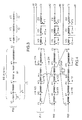
- FIG. 5 shows the AC-DC converter using the autotransformer in FIG. 4 .
- the autotransformer has three inputs for receiving a three-phase voltage and a higher number of outputs that are phase-shifted in order to supply an AC voltage with a larger number of phases allowing rectification with a lower residual ripple and with a lower re-injection of harmonic currents.
- the three-phase system whose three phases are separated by 120°, can be transformed into a system with nine phases separated by 40° which may be considered as a system of three three-phase networks offset by 40° with respect to one another.
- three bridges of six diodes are used, each bridge being supplied by one of these networks.
- These AC/DC converters with eighteen diodes are also referred to as 18-pulse converters.
- the autotransformer there are essentially three main windings wound onto three different magnetic branches of a three-branch magnetic core, and there are several auxiliary windings wound onto these three branches and connected to intermediate taps provided on the windings of one or the other of the other branches (or sometimes even on the same branch).
- FIG. 1 serves as a reminder of this principle of a three-phase transformer with three magnetic branches M 12 , M 23 and M 31 , three corresponding main windings B 12 , B 23 and B 31 and an example of auxiliary winding S 12 , S 23 , S 31 on each branch.
- the windings are shown without mutual connections, the object of FIG. 1 being only to recall the principle of a three-phase magnetic circuit.
- the following figures will show the connections between the various main and auxiliary windings of the autotransformer.
- auxiliary windings are shown next to the main windings, although, in reality, the various windings on the same magnetic branch are disposed at the same location (one around the other, or even the layers of one interspersed between the layers of the other) in order to have exactly the same magnetic flux passing through them.
- a voltage is created across the terminals of an auxiliary winding of a magnetic branch that is in phase with the voltage across the terminals of the main winding of the same branch.
- the voltage generated within the auxiliary winding depends
- an autotransformer is conventionally represented by a vector composition of the voltages across the terminals of the various windings.
- the phase and the amplitude of the voltage may be represented by a vector whose length represents the amplitude of the AC voltage (single-ended or differential) and whose orientation represents the phase from 0° to 360° of this AC voltage.
- the autotransformer converts a three-phase voltage of given amplitude into a voltage with nine phases separated by 40°, of slightly lower amplitude than that of the three-phase voltage.
- the vector compositions are determined which, starting from the initial three phases, allow the nine phases sought to be constructed.
- FIG. 2 shows a vector composition corresponding to such an autotransformer.
- the vectors used in the composition are obtained, on the one hand, starting from points representing the terminals of main or auxiliary windings and, on the other, using points representing intermediate taps of these windings.
- the voltage obtained between two intermediate taps of a main winding is in phase with the voltage on the main winding (the vectors are therefore collinear); its amplitude is a certain fraction of the voltage across the terminals of the main winding, this fraction being a function of the ratio between the number of winding turns situated between the intermediate taps and the total number of turns of the main winding; the relative length of the vector representing the voltage between two intermediate taps of a winding is determined by this ratio of number of turns.
- the voltage obtained across the terminals of an auxiliary winding associated with the main winding (in other words with the same magnetic flux passing through it hence wound at the same location on the same magnetic branch) is in phase with the voltage across the terminals of the main winding (the vectors are therefore parallel) and its amplitude is also determined by the ratio between the number of turns in the auxiliary winding and the number of turns in the main winding; the length of the vector representing the voltage on the auxiliary winding is therefore, relative to the length of the vector representing the voltage on the main winding, in the ratio of the number of turns.
- a neutral point of origin O is arbitrarily defined and the single-ended input and output voltages of the autotransformer will be referenced with respect to this point.
- the vector OE 1 represents the amplitude and the phase of the single-ended voltage present on the terminal E 1 of the three-phase power supply.
- the neutral point O is a virtual point (input and output via delta configuration) of the circuit; if it is assumed that the three-phase power supply applied to E 1 , E 2 , E 3 is well balanced, the neutral point represents the reference point where the vector sum of the voltages OE 1 , OE 2 , OE 3 is zero.
- the point O is the center of an equilateral triangle whose corners are the points E 1 , E 2 , E 3 .
- the vectors OE 2 and OE 3 of same amplitude as the vector OE 1 , are respectively oriented at +120° and ⁇ 120° to the reference vector OE 1 .
- the power supply applied to the terminals E 1 , E 2 , E 3 is a three-phase power supply in delta configuration (preferred case)
- the vectors E 1 E 2 , E 2 E 3 , E 3 E 1 represent the amplitudes and phases of the voltages between power supply lines, applied to the terminals of the main windings. They are at 120° with respect to one another.
- OE 1 represents the vector starting from O and going as far as E 1 , and not the reverse.
- phase of the single-ended voltage OE 1 (vertical direction) is chosen as phase reference.
- the direction of the vector E 1 E 2 is at +150°; that of the vector E 2 E 3 is at +270°, and that of the vector E 3 E 1 is at +30°.
- the vector composition in FIG. 2 allows nine voltages of phases at 40° to one another and of same amplitude, lower than that of the three-phase power supply voltage, to be constructed.
- k is less than 1 and may go as low as about 0.56.
- the vectors OA 1 , OA 2 , OA 3 are aligned with the vectors OE 1 , OE 2 , OE 3 , respectively, and hence are separated by 120° with respect to one another.
- the vectors of the second system define three points B 1 , B 2 , B 3 on the same circle with center O and of radius Va′.
- the vectors OB 1 , OB 2 , OB 3 can be deduced from the vectors OA 1 , OA 2 , OA 3 by rotation through +40°.
- the vectors of the third system OC 1 , OC 2 , OC 3 can be deduced from the vectors OB 1 , OB 2 , OB 3 by a further rotation through +40° (it could also have been said that the vectors of the third system can be deduced from the vectors OA 1 , OA 2 , OA 3 by a rotation through ⁇ 40°, which amounts strictly to the same thing by reversing the denotations C 1 and C 3 ).
- Three intermediate points K 1 , K′ 1 , K′′ 1 are defined on the vector E 1 E 2 which will physically constitute intermediate taps of the main winding B 12 .
- the point K 1 is the point of intersection between the vector E 1 E 2 and a straight line having its origin at the point A 1 and being parallel to the vector E 3 E 1 .
- the point K′ 1 is the point of intersection of the vector E 1 E 2 with a straight line starting from the point B 1 and traced parallel to the vector E 2 E 3 .
- the point K′′ 1 is the point of intersection of the vector E 1 E 2 with a straight line starting from the point C 1 and traced parallel to the vector E 3 E 1 .
- the intermediate taps K 2 , K′ 2 , K′′ 2 , K 3 , K′ 3 , K′′ 3 are determined.
- the points A 1 , B 1 and C 1 are determined starting from the vectors K 1 A 1 , K′ 1 B 1 and K′′ 1 C 1 whose orientations are not those of the vector E 1 E 2 .
- the voltages corresponding to these vectors will therefore be defined using the auxiliary windings; the auxiliary windings are placed on the two other magnetic branches M 23 and M 31 of the magnetic circuit. These windings will have a first end connected to an intermediate tap, K 1 , K′ 1 or K′′ 1 respectively, of the main winding B 12 and a second end which will form an output A 1 , B 1 or C 1 , respectively, of the autotransformer.
- an auxiliary winding placed on the third magnetic branch M 31 of the magnetic circuit (that which carries the third primary winding B 31 connected between E 3 and E 1 ) will be used to establish a voltage represented by the vector K 1 A 1 since this vector is parallel to the vector E 3 E 1 .
- This winding will have one end connected to the tap K 1 and its other end will form an output terminal A 1 of the autotransformer.
- an auxiliary winding placed on the second branch of the magnetic circuit (that which carries the second main winding B 23 connected between E 2 and E 3 ) will be used to establish a voltage represented by the vector K′ 1 B 1 since the vector K′ 1 B 1 is parallel to E 2 E 3 .
- This winding will have one end connected to the tap K′ 1 and its other end will form a second output B 1 of the autotransformer, phase-shifted by 40° with respect to the output A 1 .
- an auxiliary winding placed on the third magnetic branch M 31 (that which carries the main winding B 31 connected between E 3 and E 1 ) will be used to establish the voltage K′′ 1 C 1 .
- This winding will have one end connected to the intermediate tap K′′ 1 and another end defining a third output C 1 phase-shifted by 40° with respect to the second.
- an auxiliary power supply terminal M 1 is provided on the winding B 12 , in the middle of the latter, and in the same way, auxiliary terminals M 2 and M 3 with the same positioning as the terminal M 1 but on the winding B 23 and the winding B 31 , respectively.
- the three terminals M 1 , M 2 , M 3 form, on the vector composition in FIG. 2 , an equilateral triangle whose sides have half the length of the length of the vectors E 1 E 2 , E 2 E 3 and E 3 E 1 .
- the terminals E 1 , E 2 and E 3 are supplied by a three-phase voltage of amplitude Va, the voltages present on these terminals form a three-phase system of amplitude Va/2, phase-shifted by 60° with respect to the system of power supply voltages.
- the auxiliary terminals M 1 , M 2 , M 3 are connected to a three-phase connector.
- This connector may be used in order to supply the AC-DC converter when the latter does not receive any supply of power on the terminals E 1 , E 2 and E 3 , and notably when the aircraft is at an airport with its engines stopped.
- auxiliary terminals M 1 , M 2 , M 3 are not in the middle of the main windings but displaced to the right or to the left with respect to this center point, the voltages present on these terminals are in a ratio of g less than 2 with respect to the power supply voltage applied to E 1 , E 2 , E 3 .
- the system could therefore be used to supply the aircraft with an external voltage of amplitude Va/g with g less than 2. It should be noted that in this scenario no tap position can be found on the main winding that would allow a three-phase voltage below Va/2 to be obtained, in other words that g can, at most, be equal to 2.
- FIG. 3 shows the windings situated on the first branch M 12 of the magnetic circuit: the main winding B 12 situated between the input terminals E 1 and E 2 , with its intermediate taps K 1 , K′ 1 and K′′ 1 and the auxiliary power supply terminal M 1 ; and three auxiliary windings X 12 , Y 12 and Z 12 , which are situated on the same magnetic branch M 12 as the main winding B 12 and have the same magnetic flux passing through them, but which are not directly connected to the main winding B 12 .
- These auxiliary windings X 12 , Y 12 , Z 12 produce the voltages represented by the vectors K 2 A 2 , K′ 3 B 3 and K′′ 2 C 2 which must all be in phase with the voltage on the main winding B 12 .
- These windings are therefore each connected between an intermediate tap K 2 , K′ 3 or K′′ 2 on the main windings B 23 and B 31 and a respective output A 2 , B 3 or C 2 of the autotransformer.
- the second and the third magnetic branches M 23 and M 31 of the autotransformer are formed in the same manner.
- FIG. 4 shows the three magnetic branches with their respective assemblies of main and secondary windings, and this time with the connections that completely establish the desired voltage amplitudes and phases allowing the outputs A 1 , B 1 , C 1 , A 2 , B 2 , C 2 , A 3 , B 3 , C 3 to represent a nine-phase system having the desired amplitude Va′ and able to directly supply a system of three rectifier bridges each with six diodes.
- FIG. 4 shows the three magnetic branches with their respective assemblies of main and secondary windings, and this time with the connections that completely establish the desired voltage amplitudes and phases allowing the outputs A 1 , B 1 , C 1 , A 2 , B 2 , C 2 , A 3 , B 3 , C 3 to represent a nine-phase system having the desired amplitude Va′ and able to directly supply a system of three rectifier bridges each with six diodes.
- FIG. 4 shows the three magnetic branches with their respective assemblies of main and secondary windings,
- the center-tap auxiliary power supply terminals M 1 , M 2 , M 3 on the main windings are connected to an auxiliary three-phase connector CAUX for the 115 volt power supply from a three-phase ground generator.
- circuit diagram in FIG. 4 and the vector diagram in FIG. 2 are given purely by way of example of an autotransformer producing nine phases starting from three phases. Other solutions are possible and allow step-down autotransformers (this is the case in FIG. 2 ) or step-up autotransformers to be made.
- the autotransformer thus constructed is associated with a rectifier bridge with 18 diodes in order to form an AC-DC converter.
- the direct outputs (A 1 , A 2 , A 3 ) of the autotransformer are connected to a first bridge PA of six diodes Da 1 , Da 2 , Da 3 , Da′ 1 , Da′ 2 , Da′ 3 .
- the outputs phase-shifted by +40° are connected to a second bridge PB of six diodes Db 1 , Db 2 , Db 3 , Db′ 1 , Db′ 2 , Db′ 3 , and the outputs phase-shifted by ⁇ 40° are connected to a third bridge PC of six diodes Dc 1 , Dc 2 , Dc 3 , Dc′ 1 , Dc′ 2 , Dc′ 3 .
- the three rectifier bridges have common outputs S and S′ which form the outputs of the converter.
- the diode Da 1 is forward connected between the output A 1 and a positive terminal S forming one of the two DC output terminals of the converter.
- the diode Da′ 1 is reverse connected between the output A 1 and a negative terminal S′ forming the other DC output terminal of the converter.
- the diode Da 2 and the diode Da′ 2 are forward and reverse connected, respectively, between A 1 , on the one hand, and S and S′, respectively, on the other.
- the diode Db 1 and the diode Bb′ 1 are forward and reverse connected, respectively, between B 1 , on the one hand, and S and S′, on the other, and so on; one forward-biased diode is connected between one output terminal of the autotransformer and the terminal S and one reverse-biased diode is reverse connected between this output terminal and the terminal S′.
- g is the coefficient between the normal voltage Va that the converter should receive at its main inputs (for example 230 volts) and the occasional voltage Va/g that should be received by the auxiliary inputs
- center O virtual or real node of the three-phase power supply at E 1 , E 2 , E 3
- a circle of center O and of radius Va/g is traced and the intersections with vectors representing windings are noted.
- Three intersections forming an equilateral triangle of center O are chosen from amongst these intersections and these three points define auxiliary terminals that will be placed on these windings when the autotransformer is constructed.
- the three auxiliary terminals will be connected to an autotransformer. If the circle does not cross any vector representing a winding, it is because the value of g is outside of the feasible range for this type of structure.
- auxiliary terminals may be applied to simple modifications of the diagrams in FIGS. 2 and 4 or to diagrams that are widely different.
- simple modifications it may be envisioned for example that the output A 1 be obtained starting from an auxiliary winding of the branch M 23 rather than M 31 (and the same thing of course for the other outputs A 2 and A 3 by circular permutation).
- ends of the three main windings in delta configuration be not directly connected to the main inputs E 1 , E 2 and E 3 : an auxiliary winding may be connected between one main input and one end or an intermediate tap of a main winding.
- This auxiliary winding can be situated on the same magnetic branch as the main winding to whose end it is connected; it may also be envisioned (case of a step-up autotransformer) that the three main windings be connected in delta configuration but that the main inputs be connected to auxiliary windings connected to an intermediate tap of a main winding that is not situated on the same magnetic branch as the auxiliary winding.
- the variety of configurations is very wide and, depending on the configuration chosen, a range of values of g is possible. It is even possible that the auxiliary terminals be placed on auxiliary windings rather than on the main windings if the circle of radius Va/g crosses the vectors representing the auxiliary windings of the autotransformer.
Abstract
Description
-
- on the voltage value across the terminals of the associated main winding,
- on the ratio between the number of turns in the main winding and in the auxiliary winding, and
- on the direction of rotation of the current in the auxiliary winding with respect to the direction of the current in the main winding.
Va′=Va*k
n1/N=E1K1/E1E2
n′1/N=E1K′1/E1E2
and the ratio between the number of turns n″1 situated between E1 and K″1 and the total number of turns N is:
n″1/N=E1K″1/E1E2
The points A1, B1 and C1 are determined starting from the vectors K1A1, K′1B1 and K″1C1 whose orientations are not those of the vector E1E2. The voltages corresponding to these vectors will therefore be defined using the auxiliary windings; the auxiliary windings are placed on the two other magnetic branches M23 and M31 of the magnetic circuit. These windings will have a first end connected to an intermediate tap, K1, K′1 or K″1 respectively, of the main winding B12 and a second end which will form an output A1, B1 or C1, respectively, of the autotransformer.
nx/N=K2A2/E1E2
ny/N=K′3B3/E1E2
nz/N=K″2C2/E1E2
Claims (6)
Applications Claiming Priority (3)
| Application Number | Priority Date | Filing Date | Title |
|---|---|---|---|
| FR0410150A FR2875971B1 (en) | 2004-09-24 | 2004-09-24 | ALTERNATIVE-CONTINUOUS CONVERTER FOR AERONAUTICS |
| FR0410150 | 2004-09-24 | ||
| PCT/EP2005/054362 WO2006032607A1 (en) | 2004-09-24 | 2005-09-05 | Ac/dc converter for aeronautics |
Publications (2)
| Publication Number | Publication Date |
|---|---|
| US20080186749A1 US20080186749A1 (en) | 2008-08-07 |
| US7813147B2 true US7813147B2 (en) | 2010-10-12 |
Family
ID=34948838
Family Applications (1)
| Application Number | Title | Priority Date | Filing Date |
|---|---|---|---|
| US11/574,978 Active 2026-09-17 US7813147B2 (en) | 2004-09-24 | 2005-09-05 | AC/DC converter for aeronautics |
Country Status (4)
| Country | Link |
|---|---|
| US (1) | US7813147B2 (en) |
| EP (1) | EP1792387B1 (en) |
| FR (1) | FR2875971B1 (en) |
| WO (1) | WO2006032607A1 (en) |
Cited By (8)
| Publication number | Priority date | Publication date | Assignee | Title |
|---|---|---|---|---|
| RU2460202C1 (en) * | 2011-06-01 | 2012-08-27 | Государственное образовательное учреждение высшего профессионального образования "Новосибирский государственный технический университет" | Converter of ac voltage into dc voltage |
| US8492920B2 (en) | 2011-10-07 | 2013-07-23 | Ge Aviation Systems Llc | Apparatus for generating power from a turbine engine |
| US8576594B2 (en) | 2011-04-04 | 2013-11-05 | Hamilton Sundstrand Corporation | Soft starter for phase-shifting autotransformer AC-DC power converter |
| US8723385B2 (en) | 2011-10-07 | 2014-05-13 | General Electric Company | Generator |
| US8755207B2 (en) | 2011-10-12 | 2014-06-17 | Honeywell International, Inc. | Composite AC-to-DC power converter using midpoint method |
| US8873263B2 (en) | 2012-04-17 | 2014-10-28 | Hamilton Sunstrand Corporation | Dual-input 18-pulse autotransformer rectifier unit for an aircraft AC-DC converter |
| US20150001338A1 (en) * | 2013-03-08 | 2015-01-01 | Rolls-Royce North American | Aircraft and system for supplying electrical power to an aircraft electrical load |
| US10742133B1 (en) | 2019-01-25 | 2020-08-11 | Hamilton Sunstrand Corporation | Power converters, power distribution systems and methods of converting power |
Families Citing this family (9)
| Publication number | Priority date | Publication date | Assignee | Title |
|---|---|---|---|---|
| US7732974B1 (en) | 2006-11-15 | 2010-06-08 | Justin Boland | Electrostatic power generator cell and method of manufacture |
| US8730686B2 (en) | 2011-09-29 | 2014-05-20 | Hamilton Sundstrand Corporation | Dual-input nine-phase autotransformer for electric aircraft AC-DC converter |
| US8729844B2 (en) | 2012-01-18 | 2014-05-20 | Hamilton Sundstrand Corporation | Power converter with asymmetric phase shift autotransformer for alternating current (AC) motor |
| JP6222492B2 (en) * | 2012-06-26 | 2017-11-01 | エスエムエイ ソーラー テクノロジー アーゲー | Parallel inverter connected to one inductor |
| US9058929B2 (en) * | 2013-07-10 | 2015-06-16 | Honeywell International Inc. | Composite AC-to-DC power converter with boosting capabilities |
| US9601258B2 (en) * | 2014-07-11 | 2017-03-21 | The Boeing Company | Symmetrical step-up and step-down autotransformer delta topology |
| FR3069696A1 (en) * | 2017-07-31 | 2019-02-01 | Thales | VOLTAGE ELEVATOR AUTOTRANSFORMER, AND CONTINUOUS ALTERNATIVE CONVERTER COMPRISING SUCH A AUTOTRANSFORMER |
| US10665384B2 (en) * | 2017-07-31 | 2020-05-26 | Thales | Voltage step-up autotransformer, and AC-to-DC converter comprising such an autotransformer |
| CN109545528B (en) * | 2018-12-20 | 2023-10-03 | 吉安伊戈尔电气有限公司 | Three-phase-change nine-phase step-up and step-down autotransformer |
Citations (10)
| Publication number | Priority date | Publication date | Assignee | Title |
|---|---|---|---|---|
| US3641418A (en) * | 1966-03-21 | 1972-02-08 | Gen Electric | Frequency conversion system |
| US5124904A (en) * | 1990-08-17 | 1992-06-23 | Westinghouse Electric Corp. | Optimized 18-pulse type AC/DC, or DC/AC, converter system |
| US5619407A (en) | 1996-02-06 | 1997-04-08 | Robicon Corporation | Autotransformer |
| US6198647B1 (en) | 2000-07-28 | 2001-03-06 | Rockwell Technologies, Llc | Twelve-phase transformer configuration |
| US6249443B1 (en) * | 2000-07-14 | 2001-06-19 | Rockwell Technologies, Llc | Nine-phase transformer |
| US6256213B1 (en) * | 1999-06-23 | 2001-07-03 | Avionic Instruments, Inc. | Means for transformer rectifier unit regulation |
| US7005840B2 (en) * | 2002-07-26 | 2006-02-28 | Technofan | Interface for supplying power to a load from an electrical power supply network |
| US7274280B1 (en) * | 2006-05-18 | 2007-09-25 | Derek Albert Paice | Nine-phase step-up/step-down autotransformer |
| US20080130320A1 (en) * | 2004-05-07 | 2008-06-05 | Christophe Bruzy | 40 Phase-Shifting Autotransformer |
| US20080285314A1 (en) * | 2007-05-14 | 2008-11-20 | Hassan Ali Kojori | Advanced matrix converter and method for operation |
-
2004
- 2004-09-24 FR FR0410150A patent/FR2875971B1/en active Active
-
2005
- 2005-09-05 WO PCT/EP2005/054362 patent/WO2006032607A1/en active Application Filing
- 2005-09-05 US US11/574,978 patent/US7813147B2/en active Active
- 2005-09-05 EP EP05779876.1A patent/EP1792387B1/en active Active
Patent Citations (10)
| Publication number | Priority date | Publication date | Assignee | Title |
|---|---|---|---|---|
| US3641418A (en) * | 1966-03-21 | 1972-02-08 | Gen Electric | Frequency conversion system |
| US5124904A (en) * | 1990-08-17 | 1992-06-23 | Westinghouse Electric Corp. | Optimized 18-pulse type AC/DC, or DC/AC, converter system |
| US5619407A (en) | 1996-02-06 | 1997-04-08 | Robicon Corporation | Autotransformer |
| US6256213B1 (en) * | 1999-06-23 | 2001-07-03 | Avionic Instruments, Inc. | Means for transformer rectifier unit regulation |
| US6249443B1 (en) * | 2000-07-14 | 2001-06-19 | Rockwell Technologies, Llc | Nine-phase transformer |
| US6198647B1 (en) | 2000-07-28 | 2001-03-06 | Rockwell Technologies, Llc | Twelve-phase transformer configuration |
| US7005840B2 (en) * | 2002-07-26 | 2006-02-28 | Technofan | Interface for supplying power to a load from an electrical power supply network |
| US20080130320A1 (en) * | 2004-05-07 | 2008-06-05 | Christophe Bruzy | 40 Phase-Shifting Autotransformer |
| US7274280B1 (en) * | 2006-05-18 | 2007-09-25 | Derek Albert Paice | Nine-phase step-up/step-down autotransformer |
| US20080285314A1 (en) * | 2007-05-14 | 2008-11-20 | Hassan Ali Kojori | Advanced matrix converter and method for operation |
Cited By (15)
| Publication number | Priority date | Publication date | Assignee | Title |
|---|---|---|---|---|
| US8576594B2 (en) | 2011-04-04 | 2013-11-05 | Hamilton Sundstrand Corporation | Soft starter for phase-shifting autotransformer AC-DC power converter |
| RU2460202C1 (en) * | 2011-06-01 | 2012-08-27 | Государственное образовательное учреждение высшего профессионального образования "Новосибирский государственный технический университет" | Converter of ac voltage into dc voltage |
| US8492920B2 (en) | 2011-10-07 | 2013-07-23 | Ge Aviation Systems Llc | Apparatus for generating power from a turbine engine |
| US8723385B2 (en) | 2011-10-07 | 2014-05-13 | General Electric Company | Generator |
| US8723349B2 (en) | 2011-10-07 | 2014-05-13 | General Electric Company | Apparatus for generating power from a turbine engine |
| US8755207B2 (en) | 2011-10-12 | 2014-06-17 | Honeywell International, Inc. | Composite AC-to-DC power converter using midpoint method |
| US8873263B2 (en) | 2012-04-17 | 2014-10-28 | Hamilton Sunstrand Corporation | Dual-input 18-pulse autotransformer rectifier unit for an aircraft AC-DC converter |
| US20150001338A1 (en) * | 2013-03-08 | 2015-01-01 | Rolls-Royce North American | Aircraft and system for supplying electrical power to an aircraft electrical load |
| US9193311B2 (en) * | 2013-03-08 | 2015-11-24 | Rolls-Royce North American Technologies, Inc. | Aircraft and system for supplying electrical power to an aircraft electrical load |
| US20160009405A1 (en) * | 2013-03-08 | 2016-01-14 | Rolls-Royce North America, Inc. | Vehicle and system for supplying electrical power to a vehicle electrical load |
| US9487303B2 (en) * | 2013-03-08 | 2016-11-08 | Rolls-Royce North American Technologies, Inc. | Vehicle and system for supplying electrical power to a vehicle electrical load |
| US20170021783A1 (en) * | 2013-03-08 | 2017-01-26 | Rolls-Royce North American Technologies, Inc. | Vehicle and system for supplying electrical power to a vehicle electrical load |
| US9889807B2 (en) * | 2013-03-08 | 2018-02-13 | Rolls-Royce North American Technologies, Inc. | Vehicle and system for supplying electrical power to a vehicle electrical load |
| US10742133B1 (en) | 2019-01-25 | 2020-08-11 | Hamilton Sunstrand Corporation | Power converters, power distribution systems and methods of converting power |
| US11228254B2 (en) | 2019-01-25 | 2022-01-18 | Hamilton Sundstrand Corporation | Power converters, power distribution systems and methods of converting power |
Also Published As
| Publication number | Publication date |
|---|---|
| US20080186749A1 (en) | 2008-08-07 |
| EP1792387A1 (en) | 2007-06-06 |
| FR2875971A1 (en) | 2006-03-31 |
| EP1792387B1 (en) | 2015-06-24 |
| WO2006032607A1 (en) | 2006-03-30 |
| FR2875971B1 (en) | 2006-11-10 |
Similar Documents
| Publication | Publication Date | Title |
|---|---|---|
| US7813147B2 (en) | AC/DC converter for aeronautics | |
| US10312017B2 (en) | Symmetrical step-up and step-down autotransformer delta topology | |
| US20110051480A1 (en) | 20º PHASE-SHIFTING AUTOTRANSFORMER | |
| EP2320550B1 (en) | Power transformer and power converter incorporating same | |
| US6396723B2 (en) | Rectifier and transformer thereof | |
| US7474188B2 (en) | 40° phase-shifting autotransformer | |
| CA2675774C (en) | Ac to dc power converter for aerospace applications | |
| US10608523B2 (en) | 12-phase transformer rectifier | |
| EP2582027B1 (en) | Composite ac-to-dc power converter using midpoint method | |
| CN103187885A (en) | Composite ac-to-dc oower converter using wye architecture | |
| US6466466B1 (en) | Stable artificial neutral point in a three phase network of single phase rectifiers | |
| KR20170084981A (en) | Multi-pulse electromagnetic device including a linear magnetic core configuration | |
| US7750782B1 (en) | Nine-phase autotransformer | |
| US9793820B2 (en) | Six-phase supplied transformer rectifier unit | |
| EP3070725B1 (en) | Multi-phase autotransformer | |
| US11120939B2 (en) | Ten-phase auto transformer rectifier unit | |
| US9236811B2 (en) | Multiphase transformer rectifier unit | |
| ES2653867T3 (en) | Three-phase alternating voltage rectification device | |
| JP2022540927A (en) | Asymmetric 24-pulse autotransformer rectifier unit for turbine electric propulsion and related systems and methods | |
| CN109326430B (en) | Step-up autotransformer and AC-DC converter comprising such an autotransformer | |
| CN103151154A (en) | Gothic triangular phase-shifting transformer | |
| CN115668418A (en) | Autotransformer, autotransformer-rectifier unit and method for connecting an electrical device to a three-phase network via an autotransformer-rectifier unit | |
| RU2487455C1 (en) | Nine-phase converter | |
| RU2405238C1 (en) | Ac-to-dc bridge coverter | |
| Bruzy et al. | 40 phase-shifting autotransformer |
Legal Events
| Date | Code | Title | Description |
|---|---|---|---|
| AS | Assignment |
Owner name: THALES, FRANCE Free format text: ASSIGNMENT OF ASSIGNORS INTEREST;ASSIGNOR:BLANCHERY, FRANCIS;REEL/FRAME:018988/0634 Effective date: 20070203 |
|
| STCF | Information on status: patent grant |
Free format text: PATENTED CASE |
|
| FPAY | Fee payment |
Year of fee payment: 4 |
|
| MAFP | Maintenance fee payment |
Free format text: PAYMENT OF MAINTENANCE FEE, 8TH YEAR, LARGE ENTITY (ORIGINAL EVENT CODE: M1552) Year of fee payment: 8 |
|
| MAFP | Maintenance fee payment |
Free format text: PAYMENT OF MAINTENANCE FEE, 12TH YEAR, LARGE ENTITY (ORIGINAL EVENT CODE: M1553); ENTITY STATUS OF PATENT OWNER: LARGE ENTITY Year of fee payment: 12 |