US7807107B2 - Particle agglutination-evaluating container - Google Patents
Particle agglutination-evaluating container Download PDFInfo
- Publication number
- US7807107B2 US7807107B2 US12/026,142 US2614208A US7807107B2 US 7807107 B2 US7807107 B2 US 7807107B2 US 2614208 A US2614208 A US 2614208A US 7807107 B2 US7807107 B2 US 7807107B2
- Authority
- US
- United States
- Prior art keywords
- agglutination
- bottom face
- particles
- main body
- raised
- Prior art date
- Legal status (The legal status is an assumption and is not a legal conclusion. Google has not performed a legal analysis and makes no representation as to the accuracy of the status listed.)
- Active, expires
Links
Images


Classifications
-
- G—PHYSICS
- G01—MEASURING; TESTING
- G01N—INVESTIGATING OR ANALYSING MATERIALS BY DETERMINING THEIR CHEMICAL OR PHYSICAL PROPERTIES
- G01N33/00—Investigating or analysing materials by specific methods not covered by groups G01N1/00 - G01N31/00
- G01N33/48—Biological material, e.g. blood, urine; Haemocytometers
- G01N33/50—Chemical analysis of biological material, e.g. blood, urine; Testing involving biospecific ligand binding methods; Immunological testing
- G01N33/53—Immunoassay; Biospecific binding assay; Materials therefor
- G01N33/536—Immunoassay; Biospecific binding assay; Materials therefor with immune complex formed in liquid phase
- G01N33/537—Immunoassay; Biospecific binding assay; Materials therefor with immune complex formed in liquid phase with separation of immune complex from unbound antigen or antibody
-
- B—PERFORMING OPERATIONS; TRANSPORTING
- B01—PHYSICAL OR CHEMICAL PROCESSES OR APPARATUS IN GENERAL
- B01L—CHEMICAL OR PHYSICAL LABORATORY APPARATUS FOR GENERAL USE
- B01L3/00—Containers or dishes for laboratory use, e.g. laboratory glassware; Droppers
- B01L3/50—Containers for the purpose of retaining a material to be analysed, e.g. test tubes
- B01L3/508—Rigid containers without fluid transport within
- B01L3/5082—Test tubes per se
-
- G—PHYSICS
- G01—MEASURING; TESTING
- G01N—INVESTIGATING OR ANALYSING MATERIALS BY DETERMINING THEIR CHEMICAL OR PHYSICAL PROPERTIES
- G01N21/00—Investigating or analysing materials by the use of optical means, i.e. using sub-millimetre waves, infrared, visible or ultraviolet light
- G01N21/01—Arrangements or apparatus for facilitating the optical investigation
- G01N21/03—Cuvette constructions
-
- B—PERFORMING OPERATIONS; TRANSPORTING
- B01—PHYSICAL OR CHEMICAL PROCESSES OR APPARATUS IN GENERAL
- B01L—CHEMICAL OR PHYSICAL LABORATORY APPARATUS FOR GENERAL USE
- B01L2300/00—Additional constructional details
- B01L2300/06—Auxiliary integrated devices, integrated components
- B01L2300/0627—Sensor or part of a sensor is integrated
- B01L2300/0654—Lenses; Optical fibres
-
- B—PERFORMING OPERATIONS; TRANSPORTING
- B01—PHYSICAL OR CHEMICAL PROCESSES OR APPARATUS IN GENERAL
- B01L—CHEMICAL OR PHYSICAL LABORATORY APPARATUS FOR GENERAL USE
- B01L2300/00—Additional constructional details
- B01L2300/08—Geometry, shape and general structure
- B01L2300/0848—Specific forms of parts of containers
- B01L2300/0851—Bottom walls
-
- G—PHYSICS
- G01—MEASURING; TESTING
- G01N—INVESTIGATING OR ANALYSING MATERIALS BY DETERMINING THEIR CHEMICAL OR PHYSICAL PROPERTIES
- G01N21/00—Investigating or analysing materials by the use of optical means, i.e. using sub-millimetre waves, infrared, visible or ultraviolet light
- G01N21/01—Arrangements or apparatus for facilitating the optical investigation
- G01N21/03—Cuvette constructions
- G01N2021/0325—Cells for testing reactions, e.g. containing reagents
-
- G—PHYSICS
- G01—MEASURING; TESTING
- G01N—INVESTIGATING OR ANALYSING MATERIALS BY DETERMINING THEIR CHEMICAL OR PHYSICAL PROPERTIES
- G01N21/00—Investigating or analysing materials by the use of optical means, i.e. using sub-millimetre waves, infrared, visible or ultraviolet light
- G01N21/01—Arrangements or apparatus for facilitating the optical investigation
- G01N21/03—Cuvette constructions
- G01N2021/0378—Shapes
Definitions
- the present invention relates to a particle agglutination-evaluating container for use in evaluation of a particle agglutination pattern in an immunological agglutination reaction.
- the present invention relates to a particle agglutination-evaluating container for evaluation of various blood types or detection of an antigen or antibody, based on the agglutination pattern of blood cell particles.
- immunological agglutination reactions such as antigen-antibody reactions have been examined using a test tube as the reaction container.
- antigen-bound latex particles or antigen-presenting red blood cell particles and an antigen-reactive antibody are mixed in a test tube to form a particle-antibody agglutinate; the agglutinate is allowed to precipitate spontaneously or by centrifugation; and then the precipitate is loosened by shaking the test tube to evaluate the agglutination reaction. If the precipitate is not loosened, the reaction is evaluated as positive, and if loosened, it is evaluated as negative.
- a reaction container having multiple V- or U-bottomed wells such as a microplate has been generally used.
- the particle-antibody agglutinate is allowed to precipitate as described above. If the particle-antibody agglutinate is not loosened, then the agglutinate is captured on the bottom face of the reaction container, thereby forming a pattern of the particles spread on the bottom face (positive). On the other hand, if the agglutinate is loosened, then the particle gathers on the lowest region of the bottom face of the reaction container (negative). An intermediate reaction (weakly positive reaction) is detected as an intermediate agglutination pattern.
- the method enables visual or optical observation of the agglutinate captured on the bottom face of the reaction container microplate from above or below the microplate, and thus it is suitable for the examination of a great number of samples.
- the capturing efficiency of the agglutinate on the microplate bottom face depends significantly on the condition of the bottom face.
- the agglutinate should stably adhere to the bottom face in the examination, a weak agglutinate easily slides from an unprocessed smooth bottom face, indicating a false negative.
- the passive agglutination method using the container is generally called a microcolumn agglutination method.
- reaction container which consists of a card and rod-shaped microreaction tubes formed thereon, wherein the tubes are filled with insoluble particles, such as polymer or glass particles, having a diameter of 10 to 200 ⁇ m, and which allows efficient differentiation between agglutinated and unagglutinated red blood cells by centrifugation.
- insoluble particles such as polymer or glass particles
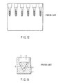
- FIG. 12 A side view of the reaction container is shown in FIG. 12 .
- EP725276 discloses a similar reaction container filled with glass beads. These devices have a characteristic in that immunologically inactive insoluble particles are used.
- each microreaction tube is used as it is held upright in the vertical direction.
- a liquid sample is injected through an inlet on top of the microreaction tube standing in the vertical direction; the container is centrifuged after reaction; and the agglutinate captured by the insoluble particles is detected visually or optically from the side wall. Presence of the agglutinate on the insoluble particles indicates positive reaction; presence of the agglutinate in the intermediate layer of the insoluble particles indicates weak positive reaction; and precipitation of the agglutinate to below the insoluble particles indicates negative reaction.
- the rod-shaped microreaction tube described above has advantages that it is possible to complete the reaction in a shorter period of time by using centrifugation, and the evaluation is also easy, because the agglutination pattern differs significantly between the positive and negative reactions.
- the agglutination pattern develops in the vertical direction and the insoluble particle layer is opaque, it is not possible to examine the reaction in the direction from above or below and thus, the observation is only made through the side wall. Therefore, in observation of the agglutinates on multiple cards, it was necessary to hold up and evaluate each card separately by visually viewing it horizontally, causing a significant obstacle to high-throughput analysis in an automatic analyzer.
- German Patent No. 10061515 discloses a microplate-shaped container having multiple reaction chambers, of which at least part of the bottom face is narrowed and which is filled with insoluble particles.
- the container enables acquisition of a flat-spread pattern of the agglutinate when the reaction is positive, and a pattern in which the non-agglutinate gathers in the narrowed region when it is negative, thus allowing observation both from above and below.
- the method still had a problem that it was not possible to detect the pattern accurately in the direction from above or below, especially when the reaction is weakly positive.
- FIG. 13 shows that, in a transparent container main body 1 having a V-bottomed well 2 , a spacer 4 having a lower face facing the bottom face of the well in parallel is placed so that there is a gap layer on a bottom face 3 of the well. Insoluble particles are filled in the gap layer formed between the spacer and the bottom face of the well, forming a fluidal separation layer 5 .
- Presence of the agglutinate on the fluidal separation layer indicates positive reaction; presence of the agglutinate in the intermediate layer of the fluidal separation layer indicates weak positive reaction; and presence of the agglutinate at the bottom of the well indicates negative reaction. It is possible to observe and identify each agglutination pattern in the direction from below the well bottom face 3 .
- an object of the present invention is to provide a particle agglutination-evaluating container that allows easy and accurate evaluation of the agglutination pattern and observation thereof in the direction from below the container, thereby enabling high-throughput analysis in an automatic analyzer.
- a transparent container main body having a bottom face including a sloping bottom face and a raised bottom face extended in a horizontal direction at the top of the sloping bottom face to form an obtuse angle with the sloping bottom face, and
- the agglutination particles form an agglutinate and are located on a top face of the fluidal separation layer when the agglutination reaction is positive, the agglutination particles do not form an agglutinate and migrate to the bottom of the sloping bottom face when the agglutination reaction is negative, and the agglutination particles form an agglutinate and are located in an intermediate region of the fluidal separation layer when the agglutination reaction is weakly positive between positive and negative, and thus agglutination is evaluated by observation from the bottom face side of the transparent container main body, where the agglutination reaction is judged positive when the agglutination particles are observed through the raised bottom face, negative when the agglutination particles are observed at the bottom end of the sloping bottom face, and weakly positive when the agglutination particles are observed in the middle of the sloping bottom face.
- a transparent container main body having a bottom face including a sloping bottom face raised in a shape of a truncated cone or pyramid, where the vertex region of the bottom face forms a raised bottom face extended in a horizontal direction;
- the agglutination particles form an agglutinate and are located on a top face of the fluidal separation layer when the agglutination reaction is positive, the agglutination particles do not form an agglutinate and migrate to the bottom of the sloping bottom face when the agglutination reaction is negative, and the agglutination particles form an agglutinate and are located in an intermediate region of the fluidal separation layer when the agglutination reaction is weakly positive between positive and negative, and thus agglutination is evaluated by observation from the bottom face side of the transparent container main body, where the agglutination reaction is judged positive when the agglutination particles are observed through the raised bottom face, negative when the agglutination particles are observed at the bottom end of the sloping bottom face, and weakly positive when the agglutination particles are observed in the middle of the sloping bottom face.
- the particle agglutination-evaluating container comprises the bottom face having a sloping bottom face and a raised bottom face extended in a horizontal direction at the top of the sloping bottom face to form an obtuse angle with the sloping bottom face, and thus enables easy and accurate observation of the agglutination pattern in the direction from below the container.
- the particle agglutination-evaluating container comprises a bottom face including a sloping bottom face raised in a shape of a truncated cone or pyramid, where the vertex region of the bottom face forms a raised bottom face extended in a horizontal direction, and thus enables easy and accurate observation of the agglutination pattern in the direction from below the container. Therefore, the container according to the present invention eliminates the disadvantage of observation from the side-wall direction and allows evaluation of a large number of samples in an automatic analyzer.
- the container according to the present invention which has a bottom face in a particular shape including a sloping face and a raised face, can be formed easily without the difficulty of placing a particular structure at a particular position, as it floats, in the space of a reaction container.
- FIG. 1 is a perspective view illustrating a particle agglutination-evaluating container according to a first embodiment of the present invention.
- FIG. 2 is a sectional view of the container, when cut along the line A-A′ shown in FIG. 1 .
- FIG. 3 shows schematic sectional views of the agglutination patterns of ( a ) positive, ( b ) weakly positive, and ( c )negative reaction, in the case of a test using the particle agglutination-evaluating container according to the first embodiment of the present invention.
- FIG. 4 shows views of the agglutination patterns of ( a ) positive, ( b ) weakly positive, and ( c ) negative reaction observed from below the container, in the case of a test using the particle agglutination-evaluating container according to the first embodiment of the present invention.
- FIG. 5 is a sectional view of a modified example 1 of a particle agglutination-evaluating container according to the first embodiment of the present invention.
- FIG. 6 is a sectional view of a modified example 2 of a particle agglutination-evaluating container according to the first embodiment of the present invention.
- FIG. 7 is a sectional view of a modified example 3 of a particle agglutination-evaluating container according to the first embodiment of the present invention.
- FIG. 8 is a perspective view of a modified example 4 of a particle agglutination-evaluating container according to the first embodiment of the present invention.
- FIG. 9 is a sectional view of the container, when cut along the line B-B′ shown in FIG. 8 .
- FIG. 10 shows views of the agglutination patterns of ( a ) positive, ( b ) weakly positive, and ( c ) negative reaction observed from below the container, in the case of a test using the particle agglutination-evaluating container according to the modified example 4 of the present invention.
- FIG. 11 is a sectional view illustrating an example of a particle agglutination-evaluating container having multiple particle agglutination-evaluating containers of the present invention aligned in parallel with each other.
- FIG. 12 is a side view illustrating a prior-art particle agglutination-evaluating container.
- FIG. 13 is a sectional view illustrating another prior-art particle agglutination-evaluating container.
- FIG. 1 is a perspective view illustrating a particle agglutination-evaluating container 10 according to the first embodiment of the present invention.
- FIG. 2 is a sectional view illustrating the particle agglutination-evaluating container 10 shown in FIG. 1 , when cut along the line A-A′.
- a transparent container main body 11 of the particle agglutination-evaluating container 10 is cylindrical in its external shape, and has a bottom face including a sloping bottom face 11 a and a raised bottom face 11 b extended horizontally at the top of the sloping bottom face 11 a to form an obtuse angle with the sloping bottom face.
- the bottom face has an inverted-V shape of a truncated circular cone, and the raised bottom face 11 b is a horizontal face.
- the transparent container main body 11 is filled with insoluble particles for separating agglutination particles depending on the degree of agglutination, forming therein a fluidal separation layer 12 .
- the transparent container main body 11 has, in its internal wall, a funnel-shaped sample inlet 13 for injecting an antibody- or antigen-containing sample collectively onto the raised bottom face 11 b of the transparent container main body 11 (for prevention of addition onto the sloping bottom face 11 a ).
- the transparent container main body 11 is made of a transparent material (for example, transparent resin) so that the agglutination pattern formed between an antibody-containing sample and antigen-immobilized agglutination particles or between an antigen-containing sample and antibody-immobilized agglutination particles can be observed, upward from the bottom side of the transparent container main body 11 .
- a transparent material for example, transparent resin
- the transparent container main body 11 has a cylindrical external shape in the first embodiment, but may have the shape of a quadrangular prism of which the bottom face is raised into the shape of a truncated quadrangular pyramid.
- the bottom face of the transparent container main body 11 has an inverted-V shape in the first embodiment, but the raised bottom face in the inverted-V shape may be rounded into an inverted-U shape (see FIGS. 5 and 6 ).
- the gradient angle of the sloping bottom face is preferably 45° to 75°, particularly preferably 55° to 75°, with respect to the horizontal plane.
- the gradient angle can be determined by drawing a tangent line on the curve. If the gradient angle is small, unagglutinated particles accumulate at the bottom and form a broadly spread agglutination pattern, making the judgment of a negative reaction more difficult. On the other hand, if the gradient angle is large, an agglutinate is less likely to be captured on the sloping face, leading to deterioration of agglutinate-capturing efficiency.
- the gradient angle of the sloping bottom face may be varied in the same transparent container main body, and may be larger in the region closer to the lower (deeper) end of the sloping bottom face. For example, as shown in FIG. 6 , if the gradient angle increases in the region closer to the bottom end of the sloping bottom face and is largest at the bottom face, precipitate of unagglutinated particles (negative agglutination pattern) can be detected more easily.
- the sloping bottom face may be surface-roughened for improvement in agglutinate-capturing efficiency.
- the roughened surface is a surface having roughness suitable for capturing weakly positive agglutinate, and for example, the sloping bottom face may have orderly steps, such as those shown in FIG. 7 (see Jpn. Pat. Appln. KOKOKU Publication No. 61-44268). For example, raised steps different in height by 2 to 50 ⁇ m in the vertical direction may be formed orderly on the sloping face at an interval of 5 to 200 ⁇ m.
- the raised bottom face 11 b is formed in the horizontal direction at the top of the sloping bottom face 11 a , forming an obtuse angle with the sloping face.
- the raised bottom face 11 b may be a flat surface as shown in FIGS. 1 and 2 or a curved surface as shown in FIGS. 5 and 6 .
- the raised bottom face need not be a flat surface, as long as a positive-reaction agglutinate located on the top face of the fluidal separation layer can be observed upward from the bottom of the transparent container main body.
- the raised bottom face has at least a flat surface region, because the flat surface region enables easy observation of the positive-reaction agglutinate in the direction from the container bottom face.
- the raised bottom face has at least a curved surface region, because the curved surface region enables easier migration of the negative unagglutinated particles toward the sloping bottom face without accumulation on the raised bottom face.
- the boundary between the sloping bottom face and the raised bottom face is not distinct.
- the “raised bottom face” is determined by observing the positive-reaction agglutinate (located on the top face of the fluidal separation layer) from the bottom of the transparent container main body by eye, and determining a part of the bottom face where the fluidal separation layer is thin and the positive-reaction agglutinate can be observed by eye.
- the width of the raised bottom face 11 b (indicated by “w” in FIG. 2 ) needs to be a sufficient width to allow observation of the positive agglutination pattern from the bottom of the transparent container main body by eye.
- the width is preferably 1 mm or more, and more preferably, 1 ⁇ 2 or less of the width of the transparent container main body, and still more preferably 1 ⁇ 3 or less of the width of the transparent container main body, in order to distinguish definitely the positive and negative agglutination patterns.
- the insoluble particles which are filled inside the transparent container main body 11 and where agglutination particles are separated depending on the degree of agglutination, are not particularly limited, as long as the insoluble particles are those used in conventional microcolumn agglutination methods. Insoluble particles higher in specific gravity are easier to handle, but the insoluble particles are not particularly limited thereto.
- a porous material may be used as the insoluble particles, as described in EP797097.
- a glass bead or a crosslinked polymer is preferably used as the insoluble particles.
- the insoluble particle diameter is preferably 25 to 200 ⁇ m.
- the insoluble particle is preferably transparent in order to enable easier observation of the agglutination pattern, but may be opaque as long as the agglutination pattern can be observed.
- the insoluble particles are filled in the transparent container main body 11 , forming the fluidal separation layer 12 .
- the insoluble particles are filled up to a height at least as high as the raised bottom face.
- the insoluble particles are filled at most to a height to give a fluidal separation layer having a thickness (indicated by “t” in FIG. 2 ) of preferably 2 mm, more preferably 1 mm, over the raised bottom face.
- t thickness
- a sample inlet 13 is attached on the internal wall of the transparent container main body 11 for the purpose of addition of an antibody- or antigen-containing sample onto the raised bottom face 11 b of the transparent container main body 11 .
- the sample-introduction space of the sample inlet may function as a reaction space for a reaction between blood cells and a sample.
- the particle agglutination-evaluating container according to the present invention may have a sample inlet integrated with the transparent container main body, as shown in FIG. 1 .
- the sample inlet may have a funnel shape, as shown in FIG. 1 .
- the sample inlet may have a shape incorporable with the transparent container main body, as shown in FIG. 6 .
- the fluidal separation layer 12 may contain a reagent for an immunological test (such as antiserum), and insoluble particles may be suspended in such a reagent solution.
- the fluidal separation layer 12 may contain an anti-A or anti-B serum causing an agglutination reaction with red blood cells in a sample solution.
- the fluidal separation layer 12 may contain a blood cell-reactive reagent (antiserum) such as an antiglobulin serum.
- antiglobulin serum is used, for example, for detection of an antibody that does not agglutinate even by a reaction with an antigen on red blood cells (imperfect antibody).
- the antibody is crosslinked by addition of an antiglobulin serum as a secondary antibody after the antigen-antibody reaction, thereby causing agglutination with the red blood cells (indirect antiglobulin test (IAT)).
- IAT indirect antiglobulin test
- An antiglobulin serum is contained in the insoluble particle layer, a reaction between red blood cells and the antibody (imperfect antibody) is preformed in a separate reaction chamber, and then the mixture is centrifuged. As a result of the centrifugation, only the blood cells (and the antibody bound thereto) migrate into the insoluble particle layer under the influence of their specific gravity, and react with the antiglobulin serum in the insoluble particle layer, thereby forming an agglutinate. In this way, an antiserum is added to the fluidal separation layer, and thereby it is possible to carry out IAT, without performing washing process of the red blood cells (B/F separation) needed for removing excessive antibodies not bound to the red blood cells.
- agglutination reaction using the particle agglutination-evaluating container of the first embodiment
- a passive agglutination method will be described, but application of the container according to the present invention is not limited thereto.
- antigen- or antibody-bound agglutination particles such as latex particles or red blood cells are reacted with a sample containing an antibody or antigen binding to the antigen or antibody bound on the agglutination particles, for a desired period in the sample-introduction space of the sample inlet 13 .
- the agglutination particles are reacted with the sample beforehand for a desired period in a separate container, and then, the mixture is introduced to the sample inlet (FIG.
- the agglutination particles are preferably colored for visual observation of the agglutination pattern.
- the agglutination particles may be naturally colored, like red blood cells, or artificially colored by a known method (for example with a colorant).
- the agglutination particles may be labeled by a label (such as a fluorescent label) enabling monitoring of the position thereof in the fluidal separation layer.
- a label such as a fluorescent label
- the container containing the reaction solution 14 of the agglutination particles and the sample is centrifuged.
- the reaction solution migrates on the fluidal separation layer 12 and then precipitates toward the sloping bottom face according to the agglutination pattern (FIG. 3 ( 2 )).
- the centrifugation condition may vary according to the gradient angle of the sloping bottom face and the kind of the used insoluble particles, but is preferably 70 G to 300 G for 5 to 10 minutes.
- the centrifugation force G is preferably lower for obtaining a positive agglutination pattern, and thus, centrifugation at 70 G to 115 G is still more preferable.
- FIGS. 3( a ) to ( c ) and 4 Examples of the agglutination patterns obtained in the agglutination reaction are schematically shown in FIGS. 3( a ) to ( c ) and 4 .
- FIG. 3 shows agglutination patterns in a sectional view similar to that in FIG. 2
- FIG. 4 shows agglutination patterns observed from the bottom.
- the observation of the agglutination pattern may be performed visually by naked eye when colored agglutination particles are used, but may instead be performed under microscope.
- an agglutinate 15 a is captured on the fluidal separation layer 12 ( FIG. 3( a )).
- the agglutinated particles can be observed clearly only in the region of the raised bottom face, because the thickness of the insoluble particles deposited on the raised bottom face is smaller than the thickness of the insoluble particles deposited on the sloping bottom face ( FIG. 4( a )).
- unagglutinated particles 15 c precipitate to the bottom of the fluidal separation layer ( FIG. 3( c )).
- the particle agglutination-evaluating container according to the present invention may be expressed as “a container comprising a container main body with a transparent raised bottom face having a mountain-like shape and a fluidal separation layer containing insoluble particles which are filled in the transparent container main body and where the agglutination particles are separated according to the degree of agglutination”.
- the mountain-like shape may be a shape of a truncated cone (see FIG. 2 ), or a shape of a truncated cone having a rounded raised bottom face (see FIGS. 5 and 6 ).
- FIG. 11 shows the sectional view of an example of the agglutination-evaluating container having multiple containers of the present invention aligned in parallel.
- each container corresponding to each well has a transparent container main body 11 including a sloping bottom face 11 a and a raised bottom face 11 b extended in a horizontal direction at the top of the sloping bottom face to form an obtuse angle with the sloping bottom face, and a fluidal separation layer 12 containing insoluble particles which are filled in each well and where the agglutination particles are separated according to the degree of agglutination.
- FIG. 5 A sectional view of a particle agglutination-evaluating container of modified example 1 is shown in FIG. 5 in which the flat raised bottom face in the first embodiment is replaced with a rounded raised bottom face.
- the rounded raised bottom face enables migration of negative unagglutinated particles toward the sloping bottom face without accumulation on the raised bottom face.
- FIG. 6 A sectional view of a particle agglutination-evaluating container of modified example 2 is shown in FIG. 6 , in which the inverted-V shape of the truncated circular cone in the first embodiment is replaced with an inverted-U shape and the gradient angle of the sloping bottom face is changed to increase in the region closer to the bottom.
- the sample inlet 13 is separated from the transparent container main body 11 and used as it is connected to the transparent container main body with screwing or pushing, whereas the sample inlet is integrated with the transparent container main body in the first embodiment.
- the modified example 2 it is possible to form a negative agglutination pattern more definitely, by increasing the gradient angle of the sloping bottom face in the region closer to the bottom end of the sloping bottom face. As shown in FIG. 6 , if the top space over the fluidal separation layer is sealed tightly when the sample inlet is connected to the transparent container main body, it is possible to prevent scattering of the sample.
- FIG. 7 A sectional view of a particle agglutination-evaluating container of modified example 3 is shown in FIG. 7 , in which the sloping bottom face having a smooth surface in the first embodiment is replaced with a sloping bottom face having a roughened surface.
- the roughened surface in the modified example 3 is formed by making multiple steps different in level on the sloping bottom face. The multiple steps can increase the efficiency of capturing the weakly positive agglutinate.
- FIG. 8 A perspective view of a particle agglutination-evaluating container of modified example 4 is shown in FIG. 8 , in which the cylindrical container in the first embodiment is replaced with a semi-cylindrical container.
- the sectional view thereof along the line B-B′ shown in FIG. 8 is shown in FIG. 9 .
- the particle agglutination-evaluating container of the modified example 4 is a container corresponding to a half of that in the first embodiment cut in the vertical direction.
- FIG. 10 shows the agglutination patterns of ( a ) positive reaction, ( b ) weakly positive reaction, and ( c ) negative reaction, observed from the bottom face side of the container, in the case of a test using the particle agglutination-evaluating container of the modified example 4.
- the transparent container main body has a bottom face including a sloping bottom face and a raised bottom face extended in a horizontal direction at the top of the sloping bottom face to form an obtuse angle with the sloping bottom face.
Landscapes
- Health & Medical Sciences (AREA)
- Immunology (AREA)
- Life Sciences & Earth Sciences (AREA)
- Chemical & Material Sciences (AREA)
- General Health & Medical Sciences (AREA)
- Analytical Chemistry (AREA)
- Engineering & Computer Science (AREA)
- Hematology (AREA)
- Biochemistry (AREA)
- Molecular Biology (AREA)
- General Physics & Mathematics (AREA)
- Pathology (AREA)
- Biomedical Technology (AREA)
- Physics & Mathematics (AREA)
- Urology & Nephrology (AREA)
- Biotechnology (AREA)
- Microbiology (AREA)
- Cell Biology (AREA)
- Food Science & Technology (AREA)
- Medicinal Chemistry (AREA)
- Clinical Laboratory Science (AREA)
- Chemical Kinetics & Catalysis (AREA)
- Automatic Analysis And Handling Materials Therefor (AREA)
- Optical Measuring Cells (AREA)
- Investigating Or Analysing Biological Materials (AREA)
Abstract
Description
Claims (15)
Applications Claiming Priority (3)
| Application Number | Priority Date | Filing Date | Title |
|---|---|---|---|
| JP2006-156266 | 2006-06-05 | ||
| JP2006156266A JP5008899B2 (en) | 2006-06-05 | 2006-06-05 | Container for particle aggregation determination |
| PCT/JP2007/061263 WO2007142174A1 (en) | 2006-06-05 | 2007-06-04 | Container for determining particle agglutination |
Related Parent Applications (1)
| Application Number | Title | Priority Date | Filing Date |
|---|---|---|---|
| PCT/JP2007/061263 Continuation WO2007142174A1 (en) | 2006-06-05 | 2007-06-04 | Container for determining particle agglutination |
Publications (2)
| Publication Number | Publication Date |
|---|---|
| US20080213131A1 US20080213131A1 (en) | 2008-09-04 |
| US7807107B2 true US7807107B2 (en) | 2010-10-05 |
Family
ID=38801425
Family Applications (1)
| Application Number | Title | Priority Date | Filing Date |
|---|---|---|---|
| US12/026,142 Active 2028-01-06 US7807107B2 (en) | 2006-06-05 | 2008-02-05 | Particle agglutination-evaluating container |
Country Status (4)
| Country | Link |
|---|---|
| US (1) | US7807107B2 (en) |
| EP (1) | EP2026069A1 (en) |
| JP (1) | JP5008899B2 (en) |
| WO (1) | WO2007142174A1 (en) |
Cited By (1)
| Publication number | Priority date | Publication date | Assignee | Title |
|---|---|---|---|---|
| WO2013126556A1 (en) * | 2012-02-21 | 2013-08-29 | Indiana University Research And Technology Corporation | Ultrahigh throughput microinjection device |
Families Citing this family (3)
| Publication number | Priority date | Publication date | Assignee | Title |
|---|---|---|---|---|
| EP2247710A4 (en) | 2008-03-03 | 2016-04-20 | Heatflow Technologies Inc | Heat flow polymerase chain reaction systems and methods |
| USD634440S1 (en) * | 2009-06-24 | 2011-03-15 | Oy Medix Biochemica Ab | Container portion of a test strip unit |
| US9040000B2 (en) * | 2012-01-26 | 2015-05-26 | Heatflow Technologies Inc. | Sample container with sensor receptacle and methods of use |
Citations (15)
| Publication number | Priority date | Publication date | Assignee | Title |
|---|---|---|---|---|
| JPS54130195A (en) | 1978-02-28 | 1979-10-09 | Suovaniemi Finnpipette | Method of and device for automatically measuring tested aggregated result |
| US4303616A (en) | 1979-06-20 | 1981-12-01 | Olympus Optical Co. Ltd. | Agglutination analyzing vessel |
| JPS58754A (en) | 1981-06-26 | 1983-01-05 | Olympus Optical Co Ltd | Vessel for decision of particle cohesion |
| US4466740A (en) * | 1980-10-09 | 1984-08-21 | Olympus Optical Co., Ltd. | Particle agglutination analyzing plate |
| JPS6144268A (en) | 1984-08-09 | 1986-03-03 | 松下電器産業株式会社 | Engine-driven heat pump device |
| JPS6360854A (en) | 1986-08-29 | 1988-03-16 | Nhk Spring Co Ltd | Taking-up device |
| US5017341A (en) * | 1988-04-19 | 1991-05-21 | Olympus Optical Co., Ltd. | Agglutination analyzing vessel |
| JPH04285858A (en) | 1990-11-09 | 1992-10-09 | Ortho Diagnostic Syst Inc | Method and device for column coagulating analysis |
| US5338689A (en) | 1987-08-24 | 1994-08-16 | Stiftung Fur Diagnostische Forschung | Method and card for detecting antigens and/or antibodies |
| JPH07294528A (en) | 1994-04-22 | 1995-11-10 | Scibiex Sarl | Method and apparatus for analysis of immunity |
| JPH087215A (en) | 1994-06-13 | 1996-01-12 | Sony Corp | Magnetic head and manufacturing method thereof |
| DE10061515A1 (en) | 1999-12-09 | 2001-06-21 | Deutsches Rotes Kreuz Blutspen | Agglutination assay for antigen or antibody, useful e.g. for blood grouping, by reaction in microvessel having pointed or rounded base |
| JP2001201505A (en) | 2000-01-18 | 2001-07-27 | Olympus Optical Co Ltd | Analytical method by using reactive particulate and analytical container |
| JP2004020535A (en) | 2002-06-20 | 2004-01-22 | Olympus Corp | Container for determining particle aggregation |
| JP4285858B2 (en) | 1999-10-27 | 2009-06-24 | 東日本旅客鉄道株式会社 | Vehicle ladder loading device |
Family Cites Families (2)
| Publication number | Priority date | Publication date | Assignee | Title |
|---|---|---|---|---|
| JPH087215B2 (en) | 1987-08-24 | 1996-01-29 | シュティフツング・フュア・ディアグノスティッシュ・フォルシュンク | Method for detecting antigen and / or antibody and test kit for detection |
| DE59608443D1 (en) | 1996-03-18 | 2002-01-24 | Diagnostische Forsch Stiftung | Particle immunoassay with a compact matrix |
-
2006
- 2006-06-05 JP JP2006156266A patent/JP5008899B2/en not_active Expired - Fee Related
-
2007
- 2007-06-04 WO PCT/JP2007/061263 patent/WO2007142174A1/en not_active Ceased
- 2007-06-04 EP EP07744648A patent/EP2026069A1/en not_active Withdrawn
-
2008
- 2008-02-05 US US12/026,142 patent/US7807107B2/en active Active
Patent Citations (17)
| Publication number | Priority date | Publication date | Assignee | Title |
|---|---|---|---|---|
| US4290997A (en) * | 1978-02-28 | 1981-09-22 | Kommandiittiyhtio Finnpipette Osmo A. Suovaniemi | Apparatus for automatic measurement of the results of agglutination tests |
| JPS54130195A (en) | 1978-02-28 | 1979-10-09 | Suovaniemi Finnpipette | Method of and device for automatically measuring tested aggregated result |
| US4303616A (en) | 1979-06-20 | 1981-12-01 | Olympus Optical Co. Ltd. | Agglutination analyzing vessel |
| US4466740A (en) * | 1980-10-09 | 1984-08-21 | Olympus Optical Co., Ltd. | Particle agglutination analyzing plate |
| JPS58754A (en) | 1981-06-26 | 1983-01-05 | Olympus Optical Co Ltd | Vessel for decision of particle cohesion |
| JPS6144268A (en) | 1984-08-09 | 1986-03-03 | 松下電器産業株式会社 | Engine-driven heat pump device |
| JPS6360854A (en) | 1986-08-29 | 1988-03-16 | Nhk Spring Co Ltd | Taking-up device |
| US5338689A (en) | 1987-08-24 | 1994-08-16 | Stiftung Fur Diagnostische Forschung | Method and card for detecting antigens and/or antibodies |
| US5017341A (en) * | 1988-04-19 | 1991-05-21 | Olympus Optical Co., Ltd. | Agglutination analyzing vessel |
| JPH04285858A (en) | 1990-11-09 | 1992-10-09 | Ortho Diagnostic Syst Inc | Method and device for column coagulating analysis |
| EP0725276A1 (en) | 1990-11-09 | 1996-08-07 | Ortho Diagnostic Systems Inc. | Column agglutination assay and device |
| JPH07294528A (en) | 1994-04-22 | 1995-11-10 | Scibiex Sarl | Method and apparatus for analysis of immunity |
| JPH087215A (en) | 1994-06-13 | 1996-01-12 | Sony Corp | Magnetic head and manufacturing method thereof |
| JP4285858B2 (en) | 1999-10-27 | 2009-06-24 | 東日本旅客鉄道株式会社 | Vehicle ladder loading device |
| DE10061515A1 (en) | 1999-12-09 | 2001-06-21 | Deutsches Rotes Kreuz Blutspen | Agglutination assay for antigen or antibody, useful e.g. for blood grouping, by reaction in microvessel having pointed or rounded base |
| JP2001201505A (en) | 2000-01-18 | 2001-07-27 | Olympus Optical Co Ltd | Analytical method by using reactive particulate and analytical container |
| JP2004020535A (en) | 2002-06-20 | 2004-01-22 | Olympus Corp | Container for determining particle aggregation |
Cited By (2)
| Publication number | Priority date | Publication date | Assignee | Title |
|---|---|---|---|---|
| WO2013126556A1 (en) * | 2012-02-21 | 2013-08-29 | Indiana University Research And Technology Corporation | Ultrahigh throughput microinjection device |
| US9885059B2 (en) | 2012-02-21 | 2018-02-06 | Indiana University Research And Technology Corporation | Ultrahigh throughput microinjection device |
Also Published As
| Publication number | Publication date |
|---|---|
| JP2007322381A (en) | 2007-12-13 |
| US20080213131A1 (en) | 2008-09-04 |
| JP5008899B2 (en) | 2012-08-22 |
| EP2026069A1 (en) | 2009-02-18 |
| WO2007142174A1 (en) | 2007-12-13 |
Similar Documents
| Publication | Publication Date | Title |
|---|---|---|
| US9176152B2 (en) | Methods and apparatuses for detection of positional freedom of particles in biological and chemical analyses and applications in immunodiagnostics | |
| US4466740A (en) | Particle agglutination analyzing plate | |
| EP3339863B1 (en) | Method for capturing exosomes | |
| US5188968A (en) | Method and reaction kit for agglutination detection | |
| US4303616A (en) | Agglutination analyzing vessel | |
| KR20040076226A (en) | Detection of agglutination of assays | |
| RU2648471C2 (en) | Method for determining result of agglutination reaction and microplate for determining products of agglutination reactions | |
| US5631166A (en) | Specimen disk for blood analyses | |
| JP2021512299A5 (en) | ||
| JP5423200B2 (en) | Analysis chip and sample analysis method | |
| KR20110013485A (en) | Improved imaging of immunomagnetically enriched rare cells | |
| US7807107B2 (en) | Particle agglutination-evaluating container | |
| KR20150107231A (en) | A microplate having well with membrane | |
| US20150056098A1 (en) | Sample analysis device and sample analysis method | |
| JP3766575B2 (en) | Analytical method and container for analysis using reactive fine particles | |
| JP4469990B2 (en) | Container for particle aggregation determination | |
| CN103599817A (en) | Immunological assay systems and methods | |
| JP4090797B2 (en) | Container for particle aggregation determination | |
| CA2486119A1 (en) | Method of isolating an endothelial cell and method of donor specific crossmatching | |
| JP7153365B2 (en) | Isolated cell specimen, method for producing isolated cell specimen, and method for detecting target cells | |
| JP2008256457A (en) | Aggregation inspection method | |
| JP2008241251A (en) | Immunological inspection carrier and inspection method using carrier thereof | |
| EP3823753A1 (en) | Multiplexed sample plate | |
| KR101798428B1 (en) | Immunoassay device and method for using the same | |
| JP2010271282A (en) | Blood type determination method and erythrocyte solid phase container therefor |
Legal Events
| Date | Code | Title | Description |
|---|---|---|---|
| AS | Assignment |
Owner name: OLYMPUS CORPORATION, JAPAN Free format text: ASSIGNMENT OF ASSIGNORS INTEREST;ASSIGNORS:TAMAI, TOYOHIRO;NARITA, HITOSHI;KANEKO, YASUNOBU;AND OTHERS;REEL/FRAME:020877/0719;SIGNING DATES FROM 20080201 TO 20080211 Owner name: OLYMPUS CORPORATION, JAPAN Free format text: ASSIGNMENT OF ASSIGNORS INTEREST;ASSIGNORS:TAMAI, TOYOHIRO;NARITA, HITOSHI;KANEKO, YASUNOBU;AND OTHERS;SIGNING DATES FROM 20080201 TO 20080211;REEL/FRAME:020877/0719 |
|
| AS | Assignment |
Owner name: BECKMAN COULTER, INC.,CALIFORNIA Free format text: ASSIGNMENT OF ASSIGNORS INTEREST;ASSIGNOR:OLYMPUS CORPORATION;REEL/FRAME:023778/0141 Effective date: 20090803 Owner name: BECKMAN COULTER, INC., CALIFORNIA Free format text: ASSIGNMENT OF ASSIGNORS INTEREST;ASSIGNOR:OLYMPUS CORPORATION;REEL/FRAME:023778/0141 Effective date: 20090803 |
|
| STCF | Information on status: patent grant |
Free format text: PATENTED CASE |
|
| FPAY | Fee payment |
Year of fee payment: 4 |
|
| MAFP | Maintenance fee payment |
Free format text: PAYMENT OF MAINTENANCE FEE, 8TH YEAR, LARGE ENTITY (ORIGINAL EVENT CODE: M1552) Year of fee payment: 8 |
|
| MAFP | Maintenance fee payment |
Free format text: PAYMENT OF MAINTENANCE FEE, 12TH YEAR, LARGE ENTITY (ORIGINAL EVENT CODE: M1553); ENTITY STATUS OF PATENT OWNER: LARGE ENTITY Year of fee payment: 12 |