US7807041B2 - Method for detecting the presence or absence of a gas bubble in an aqueous liquid - Google Patents
Method for detecting the presence or absence of a gas bubble in an aqueous liquid Download PDFInfo
- Publication number
- US7807041B2 US7807041B2 US11/216,743 US21674305A US7807041B2 US 7807041 B2 US7807041 B2 US 7807041B2 US 21674305 A US21674305 A US 21674305A US 7807041 B2 US7807041 B2 US 7807041B2
- Authority
- US
- United States
- Prior art keywords
- liquid
- sensitive region
- sensor
- amperometric sensor
- measuring chamber
- Prior art date
- Legal status (The legal status is an assumption and is not a legal conclusion. Google has not performed a legal analysis and makes no representation as to the accuracy of the status listed.)
- Expired - Fee Related, expires
Links
Images


Classifications
-
- G—PHYSICS
- G01—MEASURING; TESTING
- G01N—INVESTIGATING OR ANALYSING MATERIALS BY DETERMINING THEIR CHEMICAL OR PHYSICAL PROPERTIES
- G01N27/00—Investigating or analysing materials by the use of electric, electrochemical, or magnetic means
- G01N27/26—Investigating or analysing materials by the use of electric, electrochemical, or magnetic means by investigating electrochemical variables; by using electrolysis or electrophoresis
- G01N27/403—Cells and electrode assemblies
- G01N27/404—Cells with anode, cathode and cell electrolyte on the same side of a permeable membrane which separates them from the sample fluid, e.g. Clark-type oxygen sensors
-
- G—PHYSICS
- G01—MEASURING; TESTING
- G01N—INVESTIGATING OR ANALYSING MATERIALS BY DETERMINING THEIR CHEMICAL OR PHYSICAL PROPERTIES
- G01N27/00—Investigating or analysing materials by the use of electric, electrochemical, or magnetic means
- G01N27/26—Investigating or analysing materials by the use of electric, electrochemical, or magnetic means by investigating electrochemical variables; by using electrolysis or electrophoresis
- G01N27/416—Systems
- G01N27/4163—Systems checking the operation of, or calibrating, the measuring apparatus
Definitions
- the present invention relates to analysis systems and methods thereof, and in particular to a method for detecting the presence or absence of a gas bubble in an aqueous liquid.
- Such systems are used for blood-gas analysis or other measurements in liquid samples. Such systems are employed for instance for determining the partial oxygen or carbon dioxide pressure in blood, or the hemoglobin parameters of whole blood, and for measuring the pH-value or ion concentration or special metabolites.
- Sensor elements for determination of the parameters of interest, which elements are used for a multitude of measurements.
- sensor elements are for instance electrochemical or optical sensors for determining gas values, pH, ion values or metabolite values, or optical measuring units for the determination of hemoglobin values.
- the gas molecules to be determined diffuse from an usually aqueous exterior solution or a gas phase into the interior electrolyte chamber of the sensor via a gas-permeable membrane which is essentially fluid- and ion-impermeable.
- the interior electrolyte chamber contains electrodes for electrochemical determination of the gas, especially measuring or working electrodes, counter-electrodes and reference electrodes.
- the electrochemical reactions for determining the gas by means of amperometric methods take place.
- a frequently used gas sensor is the Clark oxygen sensor, for instance, where a gas-permeable membrane separates the interior electrolyte solution from the aqueous exterior medium, i.e., the medium to be measured.
- a gas-permeable membrane separates the interior electrolyte solution from the aqueous exterior medium, i.e., the medium to be measured.
- two electrodes dip into the interior electrolyte solution, one of which is placed immediately behind the membrane as a working electrode. After a polarization voltage of suitable strength is applied, the oxygen which has diffused through the membrane from the measurement medium into the interior electrolyte chamber, is consumed by electrochemical reduction at the working electrode and an electric current corresponding to the substance consumed flows. This current is proportional to the partial pressure of oxygen in the medium to be measured and represents the primary measurement quantity.
- electrochemical gas sensors with gas-permeable membranes are electrochemical sensors for the measurement of hydrogen by means of oxidation on platinum electrodes, for instance.
- Such electrochemical gas sensors are often used in medical and diagnostic analyzers for the determination of partial gas pressures or gas concentrations in liquids.
- they are employed in blood gas analyzers, which play an important role in medical diagnosis.
- Blood gas analyzers often are provided with a plurality of sensors for diverse parameters, which are arranged in series. The sample fluid flows through the measuring channel of a measurement chamber containing the sensors, measurement often being taken by the “stop-flow-method”, i.e., with the sample at standstill during the actual measurement.
- Systems of this type are often used for routine measurements in clinics, laboratories and by medical practitioners, thus requiring the sensors used to have long service life, high accuracy and good reproducibility.
- the gas sensor elements comprise a sample passage for the transport and intermediate storage of the sample. Between the interior electrolytic chamber and the sample passage there is a gas-permeable and essentially ion- and fluid-impermeable plastic membrane separating the interior electrolytic chamber from the sample passage. In that instance the membrane is provided in a mechanically stretched state.
- thin plastic membranes are employed in electrochemical gas sensors, with layer thicknesses in the micrometer range, which are made from hydrophobic plastic materials, especially from polytetrafluoroethylene, poly-propylene, or polyethylene. Further details concerning typical membrane materials may be found in “Measurement of Oxygen by Membrane-covered Probes” (Ellis Horwood series in analytical chemistry, 1988, Ellis Horwood Limited, page 91f).
- gaseous analytes are determined in aqueous solutions by means of electrochemical gas sensors, especially in physiological fluids such as whole blood, serum or urine
- problems may occur in certain rare cases during sample measurement or during calibration or quality control, if the sample or the calibrating or control medium does not completely fill the sample passage, or if the solution contains gas bubbles, e.g., air bubbles, in the region of the sensors.
- gas bubbles e.g., air bubbles
- gas bubbles may cause measurement errors, which will necessitate efficient checking for the presence or absence of gas bubbles in this case. Gas bubbles mostly adhere to the membrane surface.
- the present invention provides certain unobvious advantages and advancements over the prior art.
- the inventors have recognized a need for improvements in methods for detecting the presence or absence of a gas bubble in liquids.
- the present invention provides a method for the detection of a gas bubble, which typically is in at least partial contact with the sensitive region of an amperometric sensor located in a measuring chamber, in such a way that even very small gas bubbles may be definitely detected without additions or changes to the measuring chamber, thus permitting the taking of suitable counter measures.
- a method for detecting the presence or absence of a gas bubble in an aqueous liquid comprising providing an amperometric sensor positioned within a measuring chamber, wherein the amperometric sensor is configured to determine the concentration of a gaseous component dissolved in a liquid, the amperometric sensor comprising a sensitive region; positioning the liquid in the measuring chamber; taking at least one first measurement value of the gaseous component from a first portion of the liquid after a predetermined response time, the first portion located in the sensitive region of the sensor; moving the liquid along in the measuring chamber, such that a second portion of the liquid, which had previously been located outside the sensitive region of the amperometric sensor, is positioned in the sensitive region; taking at least one second measurement value of the gaseous component from the second portion of the liquid; and detecting the presence or absence of a gas bubble by comparing the first and second measured values.
- the gas bubble if present, is in at least partial contact with the sensitive region of the amperometric sensor.
- the liquid may be inferred to be free of bubbles in the sensitive region of the amperometric sensor, if the second measured value is higher by a predetermined amount than the first measured value.
- the method of the invention is based on the fact mentioned above, i.e., that amperometric gas sensors consume the analyte. It is assumed that the gas component to be determined by the amperometric sensor is also present in the gas bubble.
- the measuring process will in the course of time lead to a depletion of O 2 in the liquid in the immediate vicinity of the sensor due to the sensor consuming O 2 , and thus the amperometric signal will decrease. If the liquid is now moved along the amperometric signal will increase again by a certain amount, but the increase will not occur if a gas bubble is present.
- the second portion of the liquid may be moved to the sensitive region of the sensor in a measuring chamber with open inlet and outlet without significant change in pressure, typically by a pumping or suction device.
- a pumping or suction device typically by a pumping or suction device.
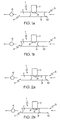
- FIGS. 1 a and 1 b schematically show a measuring set-up in accordance with an embodiment of the present invention, with a bubble-free measuring liquid;
- FIGS. 2 a and 2 b show the apparatus of FIGS. 1 a , 1 b with a gas bubble in the region of the amperometric sensor;
- FIG. 3 shows the sensor signal over time in a measurement example.
- the measurement set-up schematically shown in FIGS. 1 a , 1 b has a measuring chamber 1 with a sample passage 2 extending over the whole length, whose inlet opening is indicated by 3 .
- a pumping or suction device 6 is placed, for instance a peristaltic pump.
- the sample passage 2 may contain a plurality of different electrochemical sensors, but must have at least one amperometric sensor 7 , for instance an O 2 -sensor, whose sensitive region 8 protrudes into the sample passage 2 and into the measurement liquid 9 (e.g., a calibrating, control or sample fluid) contained therein.
- the measurement liquid 9 is separated by a separating gas bubble 10 from the subsequent liquid sample.
- FIGS. 1 a and 1 b show the measurement situation without noxious gas bubble in the sensitive region 8 of the sensor 7 .
- FIGS. 2 a and 2 b show the situation with a gas bubble 11 in at least partial contact with the sensitive region 8 of the amperometric sensor 7 .
- the measurement liquid 9 may be moved, without significant pressure change in the liquid 9 itself, for instance by means of a pumping or suction device, from a first position (see FIGS. 1 a resp. 2 a ) to a second position (see FIGS. 1 b resp. 2 b ), in such a way that a second, unused portion of the liquid 9 , which was previously held outside the sensitive region of the amperometric sensor, is now positioned in the sensitive region 8 of the amperometric sensor 7 .
- the voltage U (in mV), which is proportional to the O 2 -concentration in a liquid, e.g., a blood sample, is depicted as a function of time t (in s).
- the amperometric signal is passed to a current/voltage converter and measured as a voltage proportional to the current.
- the signal curve represents the superposition of two different processes: (1) the response of the sensor to the O 2 -value of the liquid introduced, where the signal generated by this process decreases until equilibrium is reached, and (2) the inherent O 2 -consumption of the amperometric O 2 -sensor indicated by a signal which decreases continuously over time.
- the signal becomes stable after approximately 30 seconds.
- a gas bubble 11 e.g., air
- adheres to the sensitive region 8 of the sensor 7 as shown in FIGS. 2 a and 2 b —the decrease of the signal over time t due to O 2 -consumption, will be significantly smaller than in the case of a bubble-free liquid.
- the cause of this is the fact that under normal conditions an air bubble contains much more oxygen than the same volume of an aqueous liquid.
- the gas bubble 11 will adhere to the sensitive region 8 in spite of the transport of the liquid, which will replace the liquid in the immediate vicinity of the sensor 7 by new liquid. Due to the unchanged amount of O 2 supplied by the gas bubble 11 no signal rise will occur (see curve b in FIG. 3 ).
- the term “substantially” is utilized herein to represent the inherent degree of uncertainty that may be attributed to any quantitative comparison, value, measurement, or other representation.
- the term “substantially” is also utilized herein to represent the degree by which a quantitative representation may vary from a stated reference without resulting in a change in the basic function of the subject matter at issue.
Landscapes
- Chemical & Material Sciences (AREA)
- Life Sciences & Earth Sciences (AREA)
- Health & Medical Sciences (AREA)
- Biochemistry (AREA)
- Chemical Kinetics & Catalysis (AREA)
- Electrochemistry (AREA)
- Physics & Mathematics (AREA)
- Analytical Chemistry (AREA)
- Molecular Biology (AREA)
- General Health & Medical Sciences (AREA)
- General Physics & Mathematics (AREA)
- Immunology (AREA)
- Pathology (AREA)
- Investigating Or Analysing Biological Materials (AREA)
- Sampling And Sample Adjustment (AREA)
- Investigating Or Analyzing Materials By The Use Of Electric Means (AREA)
Applications Claiming Priority (3)
| Application Number | Priority Date | Filing Date | Title |
|---|---|---|---|
| ATA1467/2004 | 2004-09-02 | ||
| ATATA1467/2004 | 2004-09-02 | ||
| AT0146704A AT502856B1 (de) | 2004-09-02 | 2004-09-02 | Verfahren zur detektion einer gasblase in einer wässrigen flüssigkeit |
Publications (2)
| Publication Number | Publication Date |
|---|---|
| US20060042963A1 US20060042963A1 (en) | 2006-03-02 |
| US7807041B2 true US7807041B2 (en) | 2010-10-05 |
Family
ID=35414567
Family Applications (1)
| Application Number | Title | Priority Date | Filing Date |
|---|---|---|---|
| US11/216,743 Expired - Fee Related US7807041B2 (en) | 2004-09-02 | 2005-08-31 | Method for detecting the presence or absence of a gas bubble in an aqueous liquid |
Country Status (4)
| Country | Link |
|---|---|
| US (1) | US7807041B2 (de) |
| EP (1) | EP1632773B1 (de) |
| AT (2) | AT502856B1 (de) |
| DE (1) | DE502005004994D1 (de) |
Families Citing this family (3)
| Publication number | Priority date | Publication date | Assignee | Title |
|---|---|---|---|---|
| AT414172B (de) | 2004-09-02 | 2006-09-15 | Hoffmann La Roche | Verfahren zur detektion einer gasblase in einer wässrigen flüssigkeit |
| EP3662268B1 (de) * | 2017-08-01 | 2021-03-24 | Roche Diagnostics GmbH | Verfahren zur überwachung des nachweisvorgangs eines analyten in einer flüssigen probe |
| KR102622195B1 (ko) * | 2021-12-02 | 2024-01-05 | 세메스 주식회사 | 약액 검사 장치와, 이를 포함하는 기판 처리 장치 및 기판을 처리하는 약액을 검사하는 방법 |
Citations (8)
| Publication number | Priority date | Publication date | Assignee | Title |
|---|---|---|---|---|
| US3874850A (en) | 1972-07-24 | 1975-04-01 | Radiometer As | Blood analyzing method and apparatus |
| US3961898A (en) | 1975-01-14 | 1976-06-08 | The United States Of America As Represented By The Secretary Of The Army | Comparator circuit for automatic analysis apparatus |
| US4358423A (en) | 1977-11-16 | 1982-11-09 | Avl Ag | Method and apparatus for monitoring and controlling the charging operation of an elongated measuring chamber |
| EP0484876B1 (de) | 1990-11-05 | 1997-07-30 | Mitsubishi Oil Company, Limited | Gerät zur dynamischen Messung des Blasengehalts einer strömenden Flüssigkeit |
| WO2001033195A1 (en) | 1999-10-29 | 2001-05-10 | Radiometer Medical A/S | Method and apparatus for detection of a bubble in a liquid |
| EP1394534A2 (de) | 2002-08-23 | 2004-03-03 | F.Hoffmann-La Roche Ag | vorrichtung zur ueberprüfung der positionierung und der blasenfreiheit einer medizinischen mikroprobe in einer durchflussmesszelle |
| US6773577B1 (en) | 2001-09-19 | 2004-08-10 | Teledyne Technologies Incorporated | Electrochemical cell bubble detection |
| EP1505381A2 (de) | 2003-08-07 | 2005-02-09 | F. Hoffmann-La Roche Ag | Verfahren zur Detektion einer Gasblase in einer Flüssigkeit |
-
2004
- 2004-09-02 AT AT0146704A patent/AT502856B1/de not_active IP Right Cessation
-
2005
- 2005-08-31 US US11/216,743 patent/US7807041B2/en not_active Expired - Fee Related
- 2005-09-01 AT AT05450146T patent/ATE404861T1/de not_active IP Right Cessation
- 2005-09-01 EP EP05450146A patent/EP1632773B1/de not_active Expired - Lifetime
- 2005-09-01 DE DE502005004994T patent/DE502005004994D1/de not_active Expired - Lifetime
Patent Citations (11)
| Publication number | Priority date | Publication date | Assignee | Title |
|---|---|---|---|---|
| US3874850A (en) | 1972-07-24 | 1975-04-01 | Radiometer As | Blood analyzing method and apparatus |
| US3961898A (en) | 1975-01-14 | 1976-06-08 | The United States Of America As Represented By The Secretary Of The Army | Comparator circuit for automatic analysis apparatus |
| US4358423A (en) | 1977-11-16 | 1982-11-09 | Avl Ag | Method and apparatus for monitoring and controlling the charging operation of an elongated measuring chamber |
| EP0484876B1 (de) | 1990-11-05 | 1997-07-30 | Mitsubishi Oil Company, Limited | Gerät zur dynamischen Messung des Blasengehalts einer strömenden Flüssigkeit |
| WO2001033195A1 (en) | 1999-10-29 | 2001-05-10 | Radiometer Medical A/S | Method and apparatus for detection of a bubble in a liquid |
| US20030080002A1 (en) * | 1999-10-29 | 2003-05-01 | Michael Taagaard | Method and apparatus for detection of a bubble in a liquid |
| US6773577B1 (en) | 2001-09-19 | 2004-08-10 | Teledyne Technologies Incorporated | Electrochemical cell bubble detection |
| EP1394534A2 (de) | 2002-08-23 | 2004-03-03 | F.Hoffmann-La Roche Ag | vorrichtung zur ueberprüfung der positionierung und der blasenfreiheit einer medizinischen mikroprobe in einer durchflussmesszelle |
| US7297241B2 (en) * | 2002-08-23 | 2007-11-20 | Roche Diagnostics Operations, Inc. | Method and a device for monitoring a medical microsample in the flow measuring cell of an analyzer |
| EP1505381A2 (de) | 2003-08-07 | 2005-02-09 | F. Hoffmann-La Roche Ag | Verfahren zur Detektion einer Gasblase in einer Flüssigkeit |
| US7084646B2 (en) * | 2003-08-07 | 2006-08-01 | Roche Diagnostics Operations, Inc. | Method of detecting a gas bubble in a liquid |
Non-Patent Citations (4)
| Title |
|---|
| Ateya, D.A. et al., "Impedance-based response of an electrolytic gas bubble to pressure in microfluidic channels", Sensors and Actuators A, Elsevier Sequoia S.A., Lausanne, Ch. Bd. 122, Nr. 2, Aug. 26, 2005, pp. 235-241. |
| Linek, V., Vacek, V., Sinkule, J., Benes, P., "Measurement of Oxygen by Membrane-Covered Probes: Guidelines for Applications in Chemical and Biochemical Engineering", Ellis Horwood Limited, 1988, pp. 91-93. |
| Maisonhaute, E. et al., "Microelectrode study of single cavitational bubbles induced by 500 kHz ultrasound", Ultrasonics: Sonochemistry, Butterworth-Heinemann, GB, Bd. 9, Nr. 5, Oct. 2002, pp. 275-283. |
| Park, J. et al., "A Simple on-chip self-diagnosis/self-calibration method of oxygen microsensor using electrochemically generated bubbles", Sensors and Actuators B, Elsevier Sequoia S.A., Lausanne, Ch, Bd. 108, Nr. 1-2, 22. Jul. 2005, pp. 633-638. |
Also Published As
| Publication number | Publication date |
|---|---|
| US20060042963A1 (en) | 2006-03-02 |
| AT502856A1 (de) | 2007-06-15 |
| DE502005004994D1 (de) | 2008-09-25 |
| ATE404861T1 (de) | 2008-08-15 |
| AT502856B1 (de) | 2007-10-15 |
| EP1632773B1 (de) | 2008-08-13 |
| EP1632773A1 (de) | 2006-03-08 |
Similar Documents
| Publication | Publication Date | Title |
|---|---|---|
| US4172770A (en) | Flow-through electrochemical system analytical method | |
| EP2275808B1 (de) | Verfahren zur kalibrierung elektrochemischer sensoren | |
| US10877053B2 (en) | Method of determining an analyte concentration | |
| CA3105025C (en) | Stacked sensor assembly for fluid analyzer | |
| CA3031081C (en) | System and method for optical whole blood hemolysis detection | |
| US8354015B2 (en) | Detection of the presence or absence of a gas bubble by dynamic sensor response | |
| US20260009809A1 (en) | Method of detecting an obstruction in a fluid analyzer | |
| US7807041B2 (en) | Method for detecting the presence or absence of a gas bubble in an aqueous liquid | |
| JP2000511640A (ja) | ポーラログラフセンサー | |
| US5238853A (en) | Process and apparatus for the electrochemical determination of oxygen in a blood gas analyzer | |
| US20240125727A1 (en) | Electrochemical measurement with additional reference measurement | |
| EP3814773B1 (de) | Konturierter probenweg für einen flüssigkeitsanalysator | |
| JPS5838745B2 (ja) | 自動式血液ガス分析での測定値検知方法 | |
| CA3105581C (en) | Contoured sample path for fluid analyzer | |
| EP4602181A1 (de) | Verfahren zur sensorkalibrierung | |
| EP4659030A1 (de) | Verfahren und vorrichtung zum nachweis von hämolyse | |
| JPS6130754A (ja) | 電気化学センサを用いた検査装置 |
Legal Events
| Date | Code | Title | Description |
|---|---|---|---|
| AS | Assignment |
Owner name: ROCHE DIAGNOSTICS OPERATIONS, INC., INDIANA Free format text: ASSIGNMENT OF ASSIGNORS INTEREST;ASSIGNOR:ROCHE DIAGNOSTICS GMBH;REEL/FRAME:016833/0049 Effective date: 20050905 |
|
| AS | Assignment |
Owner name: ROCHE DIAGNOSTICS GMBH, AUSTRIA Free format text: ASSIGNMENT OF ASSIGNORS INTEREST;ASSIGNORS:KALTENBECK, HEINZ;GRUEBLER, ROBERT;LANDSCHUETZER, EGON;SIGNING DATES FROM 20050826 TO 20050831;REEL/FRAME:016839/0076 Owner name: ROCHE DIAGNOSTICS GMBH, AUSTRIA Free format text: ASSIGNMENT OF ASSIGNORS INTEREST;ASSIGNORS:KALTENBECK, HEINZ;GRUEBLER, ROBERT;LANDSCHUETZER, EGON;REEL/FRAME:016839/0076;SIGNING DATES FROM 20050826 TO 20050831 |
|
| FPAY | Fee payment |
Year of fee payment: 4 |
|
| FEPP | Fee payment procedure |
Free format text: MAINTENANCE FEE REMINDER MAILED (ORIGINAL EVENT CODE: REM.) |
|
| LAPS | Lapse for failure to pay maintenance fees |
Free format text: PATENT EXPIRED FOR FAILURE TO PAY MAINTENANCE FEES (ORIGINAL EVENT CODE: EXP.); ENTITY STATUS OF PATENT OWNER: LARGE ENTITY |
|
| STCH | Information on status: patent discontinuation |
Free format text: PATENT EXPIRED DUE TO NONPAYMENT OF MAINTENANCE FEES UNDER 37 CFR 1.362 |
|
| FP | Lapsed due to failure to pay maintenance fee |
Effective date: 20181005 |