US7806641B2 - Substrate processing system having improved substrate transport system - Google Patents

Substrate processing system having improved substrate transport system Download PDF

Info

Publication number
US7806641B2
US7806641B2 US11/847,956 US84795607A US7806641B2 US 7806641 B2 US7806641 B2 US 7806641B2 US 84795607 A US84795607 A US 84795607A US 7806641 B2 US7806641 B2 US 7806641B2
Authority
US
United States
Prior art keywords
rollers
load lock
substrate
process chamber
processing system
Prior art date
Legal status (The legal status is an assumption and is not a legal conclusion. Google has not performed a legal analysis and makes no representation as to the accuracy of the status listed.)
Expired - Fee Related, expires
Application number
US11/847,956
Other versions
US20090060689A1 (en
Inventor
George X. Guo
Kai-An Wang
Current Assignee (The listed assignees may be inaccurate. Google has not performed a legal analysis and makes no representation or warranty as to the accuracy of the list.)
Ascentool Inc
Original Assignee
Ascentool Inc
Priority date (The priority date is an assumption and is not a legal conclusion. Google has not performed a legal analysis and makes no representation as to the accuracy of the date listed.)
Filing date
Publication date
Application filed by Ascentool Inc filed Critical Ascentool Inc
Priority to US11/847,956 priority Critical patent/US7806641B2/en
Publication of US20090060689A1 publication Critical patent/US20090060689A1/en
Priority to US12/860,907 priority patent/US8408858B2/en
Application granted granted Critical
Publication of US7806641B2 publication Critical patent/US7806641B2/en
Assigned to Ascentool, Inc reassignment Ascentool, Inc ASSIGNMENT OF ASSIGNORS INTEREST (SEE DOCUMENT FOR DETAILS). Assignors: GUO, GEORGE X., WANG, KAI-AN
Expired - Fee Related legal-status Critical Current
Adjusted expiration legal-status Critical

Links

Images

Classifications

    • HELECTRICITY
    • H01ELECTRIC ELEMENTS
    • H01LSEMICONDUCTOR DEVICES NOT COVERED BY CLASS H10
    • H01L21/00Processes or apparatus adapted for the manufacture or treatment of semiconductor or solid state devices or of parts thereof
    • H01L21/67Apparatus specially adapted for handling semiconductor or electric solid state devices during manufacture or treatment thereof; Apparatus specially adapted for handling wafers during manufacture or treatment of semiconductor or electric solid state devices or components ; Apparatus not specifically provided for elsewhere
    • H01L21/677Apparatus specially adapted for handling semiconductor or electric solid state devices during manufacture or treatment thereof; Apparatus specially adapted for handling wafers during manufacture or treatment of semiconductor or electric solid state devices or components ; Apparatus not specifically provided for elsewhere for conveying, e.g. between different workstations
    • H01L21/67739Apparatus specially adapted for handling semiconductor or electric solid state devices during manufacture or treatment thereof; Apparatus specially adapted for handling wafers during manufacture or treatment of semiconductor or electric solid state devices or components ; Apparatus not specifically provided for elsewhere for conveying, e.g. between different workstations into and out of processing chamber
    • H01L21/67742Mechanical parts of transfer devices
    • CCHEMISTRY; METALLURGY
    • C23COATING METALLIC MATERIAL; COATING MATERIAL WITH METALLIC MATERIAL; CHEMICAL SURFACE TREATMENT; DIFFUSION TREATMENT OF METALLIC MATERIAL; COATING BY VACUUM EVAPORATION, BY SPUTTERING, BY ION IMPLANTATION OR BY CHEMICAL VAPOUR DEPOSITION, IN GENERAL; INHIBITING CORROSION OF METALLIC MATERIAL OR INCRUSTATION IN GENERAL
    • C23CCOATING METALLIC MATERIAL; COATING MATERIAL WITH METALLIC MATERIAL; SURFACE TREATMENT OF METALLIC MATERIAL BY DIFFUSION INTO THE SURFACE, BY CHEMICAL CONVERSION OR SUBSTITUTION; COATING BY VACUUM EVAPORATION, BY SPUTTERING, BY ION IMPLANTATION OR BY CHEMICAL VAPOUR DEPOSITION, IN GENERAL
    • C23C14/00Coating by vacuum evaporation, by sputtering or by ion implantation of the coating forming material
    • C23C14/22Coating by vacuum evaporation, by sputtering or by ion implantation of the coating forming material characterised by the process of coating
    • C23C14/56Apparatus specially adapted for continuous coating; Arrangements for maintaining the vacuum, e.g. vacuum locks
    • C23C14/564Means for minimising impurities in the coating chamber such as dust, moisture, residual gases
    • C23C14/566Means for minimising impurities in the coating chamber such as dust, moisture, residual gases using a load-lock chamber
    • HELECTRICITY
    • H01ELECTRIC ELEMENTS
    • H01LSEMICONDUCTOR DEVICES NOT COVERED BY CLASS H10
    • H01L21/00Processes or apparatus adapted for the manufacture or treatment of semiconductor or solid state devices or of parts thereof
    • H01L21/67Apparatus specially adapted for handling semiconductor or electric solid state devices during manufacture or treatment thereof; Apparatus specially adapted for handling wafers during manufacture or treatment of semiconductor or electric solid state devices or components ; Apparatus not specifically provided for elsewhere
    • H01L21/677Apparatus specially adapted for handling semiconductor or electric solid state devices during manufacture or treatment thereof; Apparatus specially adapted for handling wafers during manufacture or treatment of semiconductor or electric solid state devices or components ; Apparatus not specifically provided for elsewhere for conveying, e.g. between different workstations
    • H01L21/67739Apparatus specially adapted for handling semiconductor or electric solid state devices during manufacture or treatment thereof; Apparatus specially adapted for handling wafers during manufacture or treatment of semiconductor or electric solid state devices or components ; Apparatus not specifically provided for elsewhere for conveying, e.g. between different workstations into and out of processing chamber
    • H01L21/67748Apparatus specially adapted for handling semiconductor or electric solid state devices during manufacture or treatment thereof; Apparatus specially adapted for handling wafers during manufacture or treatment of semiconductor or electric solid state devices or components ; Apparatus not specifically provided for elsewhere for conveying, e.g. between different workstations into and out of processing chamber horizontal transfer of a single workpiece

Definitions

  • the in-line system requires two load locks and an active transport system either inside vacuum or through the vacuum envelope.
  • the cluster tool requires one or more large central transfer modules to actively transport the work pieces.
  • the transport mechanism is required to move the work pieces between various process stations.
  • the transport mechanism is required not to introduce gas or air to the vacuum or controlled environment.
  • the transport mechanism can use low power and low out-gassing vacuum motors, or use bellows or seals to transfer motion from outside the vacuum.
  • the typical moving mechanism carries the entire substrate and typically requires heavy and expensive mechanism.
  • the seals or bellows have limited lifetime and are also expensive.
  • the active motors require constant monitoring and are a major cause of failures. The complexity of the aforementioned active transport mechanisms increases the system cost and reduces reliability.
  • the present invention relates to a substrate processing system that includes a first load lock, a process chamber having a first opening to allow an exchange of a substrate between the first load lock and the first process chamber, first rollers in the process chamber; and second rollers in the first load lock, wherein the first rollers and the second rollers are configured to transport a substrate thereon through the first opening between the first load lock and the process chamber, wherein the first rollers and the second rollers are not rotated by an active transport mechanism.
  • FIG. 1I is a side cross-sectional view of the substrate processing system of FIG. 1A showing that the removal of the first substrate from the process chamber.
  • the second substrate 141 can be pulled by the mechanism 127 from the load lock 110 into the process chamber 120 , as shown in FIG. 1J .
  • the pulling can be implemented by an attractive magnetic force between magnets that are mounted at the end of the mechanism 127 and on the edge of a holder for the substrate 140 (or 141 ).
  • the pulling can also be implemented by mechanically engaging the mechanism 127 to the edge of a holder for the substrate 140 (or 141 ).
  • the isolation valve 122 can shut the opening 121 .
  • the substrate 141 is ready for processing such as material depositions in a vacuum environment.
  • the substrate 140 can be unloaded from the load lock 110 and new substrates can be loaded into the load lock 110 through the opening 131 .
  • the steps illustrated in the FIGS. 1E to 1K can be repeated to process a large number of substrates.
  • the substrate 140 or 141 can be formed by a single piece, or include multiple substrates placed or held on a carrier. It should also be noted that there can be more than two stacks of rollers in the load lock to achieve the effect.
  • the loading and unloading of the substrates as well as the processing of the substrates in the process chamber can all be conducted in parallel.
  • the throughput of the substrate processing system can be significantly improved.
  • the second load lock can include stacks of rollers that can hold and transport a multiple of substrates.
  • the disclosed substrate processing system can be tilted to one direction to create a bias.
  • the substrate processing system 200 can be tilted toward the process chamber 120 .
  • the transport mechanism can push the substrate 140 left upward into the load lock 110 .
  • One or more stoppers can be included in the load lock 110 to hold the substrate 140 in place once the substrate is in the load lock 110 .
  • the mechanism 127 can be withdrawn from the process chamber 120 to allow the isolation valve 122 to shut and the substrate to receive processing steps. After processing of the substrate, the isolation valve 122 can open. The mechanism 127 can push the substrate out of the process chamber 120 and into the load lock 110 .
  • the tilting of the disclosed substrate processing system is not limited to tilt movement around a single rotation axis.
  • the disclosed substrate processing system can tilt around two rotation axes to move a substrate in two dimensions in the process chamber or a load lock.
  • the substrate can be reliably positioned in two, three, four, or more locations in the process chamber or the load locks.
  • the multiple holding locations for the substrate in the process chamber can allow multiple substrates to be processed at different process station, including in parallel processing operations.
  • the multiple holding locations for the substrate in the load locks allow multiple substrates to be loaded and unloaded from the substrate processing system.

Landscapes

  • Engineering & Computer Science (AREA)
  • Chemical & Material Sciences (AREA)
  • Power Engineering (AREA)
  • Condensed Matter Physics & Semiconductors (AREA)
  • General Physics & Mathematics (AREA)
  • Manufacturing & Machinery (AREA)
  • Computer Hardware Design (AREA)
  • Microelectronics & Electronic Packaging (AREA)
  • Physics & Mathematics (AREA)
  • Robotics (AREA)
  • Chemical Kinetics & Catalysis (AREA)
  • Materials Engineering (AREA)
  • Mechanical Engineering (AREA)
  • Metallurgy (AREA)
  • Organic Chemistry (AREA)
  • Container, Conveyance, Adherence, Positioning, Of Wafer (AREA)
  • Physical Vapour Deposition (AREA)

Abstract

A substrate processing system includes a first load lock, a process chamber having a first opening to allow an exchange of a substrate between the first load lock and the first process chamber, first rollers in the process chamber; and second rollers in the first load lock, wherein the first rollers and the second rollers are configured to transport a substrate thereon through the first opening between the first load lock and the process chamber. The first rollers and the second rollers are not rotated by an active transport mechanism.

Description

TECHNICAL FIELD
This application relates to an apparatus for depositing material on a substrate, etching substrate, and thermal processing in a vacuum or reduced pressure environment.
BACKGROUND
Material deposition and other substrate processing are widely used in window glass coating, flat panel display manufacturing, coating on flexible films (such as webs), hard disk coating, industrial surface coating, semiconductor wafer processing, photovoltaic panels, and other applications. Materials are sputtered off a target or vaporized from a source and deposited on a substrate. Materials can also be deposited by chemical vapor deposition method. A deposition process may include the following steps: a substrate can be placed in the process chamber. The chamber is evacuated and back filled with a desirable gas. The deposition is carried out. The process chamber can be vented before the substrate is taken out. The evacuation of the process chamber can take much time and limit the throughput of the deposition system. In addition, residues of the atmosphere or reaction with atmosphere can also affect the quality of deposited material.
To address the issues of throughput and environment control, one can employ a load lock in connection with a processing chamber. A substrate can be loaded in the load lock in an atmospheric environment. The load lock is then evacuated to vacuum or to reach conditions similar to the process chamber. The substrate is then transported by a transport mechanism into the process chamber to conduct processing steps such as cleaning, etching, and deposition. The substrate is then removed from the process chamber to the load lock. Commercial vacuum processing equipment can include the following types: single load lock and single process chamber, in-line system with one load lock at each end of the system, cluster tool with one or more central substrate transfer modules. The single load lock and single process chamber system requires an active transportation mechanism to carry entire substrate over a long distance without mechanical support and can not carry heavy substrate. In addition, most single load lock and single process chamber system can only load one substrate at a time and have limited throughput. The in-line system requires two load locks and an active transport system either inside vacuum or through the vacuum envelope. The cluster tool requires one or more large central transfer modules to actively transport the work pieces. When several process chambers are present, the transport mechanism is required to move the work pieces between various process stations. The transport mechanism is required not to introduce gas or air to the vacuum or controlled environment. The transport mechanism can use low power and low out-gassing vacuum motors, or use bellows or seals to transfer motion from outside the vacuum. The typical moving mechanism carries the entire substrate and typically requires heavy and expensive mechanism. The seals or bellows have limited lifetime and are also expensive. The active motors require constant monitoring and are a major cause of failures. The complexity of the aforementioned active transport mechanisms increases the system cost and reduces reliability.
Therefore there is a need for a simple and reliable system for deposition or other vacuum processing operations having desired throughput and deposition quality.
SUMMARY
In one aspect, the present invention relates to a substrate processing system that includes a first load lock, a process chamber having a first opening to allow an exchange of a substrate between the first load lock and the first process chamber, first rollers in the process chamber; and second rollers in the first load lock, wherein the first rollers and the second rollers are configured to transport a substrate thereon through the first opening between the first load lock and the process chamber, wherein the first rollers and the second rollers are not rotated by an active transport mechanism.
In another aspect, the present invention relates to a substrate processing system that includes a first load lock; a process chamber having a first opening to allow an exchange of a substrate between the first load lock and the first process chamber; first rollers in the process chamber; a first stack of second rollers in the first load lock; and a second stack of second rollers in the first load lock, wherein the second stack of second rollers are at a different height from the first stack of rollers, wherein the first rollers and the first stack of the second rollers are configured to transport a first substrate thereon through the first opening between the first load lock and the process chamber, and wherein the first rollers and the second stack of the second rollers are configured to transport a second substrate thereon through the first opening between the first load lock and the process chamber.
In another aspect, the present invention relates to a substrate processing system that includes a first load lock; a first process chamber having a first opening to allow an exchange of a substrate between the first load lock and the first process chamber; a second process chamber having a second opening to allow an exchange of the substrate between the first process chamber and the second process chamber; a second load lock having a second opening to allow an exchange of the substrate between the second load lock and the second process chamber; first rollers in the first load lock; second roller in the first process chamber, wherein the first rollers and the second rollers are configured to transport the substrate thereon through the first opening between the first load lock and the first process chamber; third roller in the second process chamber, wherein the second rollers and the third rollers are configured to transport the substrate thereon through the second opening between the first process chamber and the second process chamber; and fourth rollers in the second load lock, wherein the third rollers and the fourth rollers are configured to transport the substrate thereon through the third opening between the second process chamber and the second load lock, wherein the first rollers, the second rollers, the third rollers, and the fourth rollers are not rotated by an active transport mechanism.
The method includes Implementations of the system may include one or more of the following. The first rollers and the second rollers can transport the substrate substantially within a plane. The second rollers can include a first stack of rollers and a second stack of rollers at a different height from the first stack of rollers. The substrate processing system can further include a first transport mechanism configured to move the first stack of rollers to substantially the same height as the first rollers, wherein the first rollers and the first stack of rollers are configured to transport the substrate substantially through the first opening between the first load lock and the process chamber. The first transport mechanism can include move the second stack of rollers to substantially the same height as the first rollers, and wherein the first rollers and the second stack of rollers are configured transport the substrate substantially through the first opening between the first load lock and the process chamber. The substrate processing system can further include a second transport mechanism configured to move the substrate on the first rollers and the second rollers. The second transport mechanism can include push and pull the substrate on the first rollers and at least a portion of the second rollers. At least one of the first load lock and the process chamber can tilt to allow the substrate to move under gravitation on the first rollers and the second rollers. The tilt angle can be below 33 degree relative to the horizontal direction. The tilt angle can be between 1 degree and 10 degrees relative to the horizontal direction. At least one of the first load lock and the process chamber can tilt to a first tilt angle to allow the substrate to move under gravitation on the first rollers and the second rollers from the first load lock to the process chamber, and wherein at least one of the first load lock and the process chamber is configured to tilt to a second tilt angle to allow the substrate to move under gravitation on the first rollers and the second rollers from the process chamber to the first load lock. The process chamber can include at least one deposition source configured to provide a material to be deposited on the substrate. The first load lock can include at least one deposition source configured to provide a material to be deposited on the substrate. The substrate processing system can further include a gate configured to close the first opening to isolate the interior of the first process chamber from the interior of the first load lock. The first load lock can include an opening through which the substrate is loaded into the first load lock therein or unloaded from the first load lock therein. The substrate processing system can further include a second load lock configured to connect with the process chamber through a second opening in the chamber wall; and third rollers in the second load lock, wherein the second rollers and the third rollers are configured to transport a substrate thereon through the second opening between the second load lock and the process chamber. The first load lock and the second load lock can be disposed on opposite sides of the process chamber. The second rollers can include a first stack of rollers and a second stack of rollers at a different height from the first stack of rollers. The first load lock, the process chamber, and the second load lock can be configured to tilt to allow the substrate to move under gravitation on at least one of the first rollers, the second rollers, and the third rollers.
Embodiments may include one or more of the following advantages. The disclosed systems and methods can reduce system complexity and manufacturing cost comparing to some convention systems. For example, a single load lock chamber can continuously feed the process chamber with substrates without delay. A substrate in the process chamber in the disclosed substrate processing system can be transported on rollers by a small force or by gravitation applied to the substrate. The rollers are rotated by the movement of the substrate instead of being directly driven by a heavy and complex motorized transport mechanism (e.g. active transport mechanism) as in some conventional systems. The removal of such active transport systems for the substrates can also reduce the size and footprint of the substrate processing systems.
Another advantage of the disclosed system is that the substrate mechanism is more reliable compared to some conventional systems that include bellows or sealing components which are prune to failures. The substrate carried by rollers can reliably be moved by a small force or by gravitation in the disclosed substrate processing system.
Another advantage of the disclosed system is that the contamination related to motorized mechanisms in some conventional systems can be reduced or eliminated by using a cleaner gravity driven transport mechanism for the substrates.
The disclosed systems and methods can also improve throughput by using a continuous workflow between an input load lock and an output load lock.
The details of one or more embodiments are set forth in the accompanying drawings and in the description below. Other features, objects, and advantages of the invention will become apparent from the description and drawings, and from the claims.
BRIEF DESCRIPTION OF THE DRAWINGS
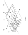
FIG. 1A is a perspective view of a substrate processing system having an improved substrate transport system and a process chamber.
FIG. 1B is a cross-sectional perspective view of the improved substrate transport system of FIG. 1A.
FIG. 1C is a perspective view of the substrate processing system of FIG. 1A with deposition sources or other processing sources installed in load lock and process chamber.
FIG. 1D is a side cross-sectional view of the substrate processing system having the improved substrate transport system of FIG. 1A.
FIG. 1E is a side cross-sectional view of the substrate processing system of FIG. 1A illustrating the loading of a first substrate in the load lock.
FIGS. 1F and 1G are side cross-sectional views of the substrate processing system of FIG. 1A illustrating the loading of the first substrate in the process chamber.
FIG. 1H is a side cross-sectional view of the substrate processing system of FIG. 1A showing that a second substrate is loaded in the load lock while the first substrate is in the process chamber.
FIG. 1I is a side cross-sectional view of the substrate processing system of FIG. 1A showing that the removal of the first substrate from the process chamber.
FIGS. 1J and 1K are side cross-sectional views of the substrate processing system of FIG. 1A illustrating the loading of a second substrate from the load lock into the process chamber.
FIG. 2 is a cross-sectional view of another substrate processing system having an improved substrate transport system and a process chamber.
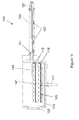
FIG. 3A is a cross-sectional view of another substrate processing system having an improved substrate transport system and a process chamber while the substrate processing system is tilted to one direction.
FIG. 3B is a cross-sectional view of the substrate processing system in FIG. 3A while the substrate processing system is tilted to another direction.
FIG. 4 is a cross-sectional view of another substrate processing system having an improved substrate transport system and a multiple of process chambers.
DETAILED DESCRIPTION
Referring to FIGS. 1A-1K, a substrate processing system 100 includes a load lock 110 and a process chamber 120. The process chamber 120 can be evacuated during material deposition and other processing steps such as cleaning, etching etc. The substrate processing system 100 can also include sources 150 for providing materials to be deposited or processed on a substrate 140, 141. The process chamber 120 can include proper electrodes for establishing DC or AC voltages between the substrate and the other components in the process chamber 120 (e.g. the chamber wall or a backing plate on the target). A vacuum pump can be connected to the process chamber 120 to produce a vacuum environment around the substrate 140, 141 during processing operations. The sources 150 can include one or more targets and one or more magnetron sources. The sources 150 can also be shower head for distributing chemicals, ion source for substrate cleaning, heating or cooling source. The interiors of the load lock 110 can be connected to the interior of the process chamber 120 by openings 121. The opening 121 can be closed to isolate the interiors of the load lock 110 from the interior of the process chamber 120 by an isolation valve 122. The load lock 110 can optionally include a source 151 for deposition or other processing operations.
A transport system for transporting a substrate 140, 141 can include a plurality of rollers 125 mounted in the process chamber 120, and a plurality of rollers 115 and 116 mounted in the load lock 110. A substrate 140, 141 can be placed on the rollers 115 and 116 or the rollers 125 and held down the rollers by gravity, magnetic forces, or mechanical stopper near edge of the substrate. The substrate 140, 141 placed on the rollers 115, 125, 126 can be moved by a tilt in the process chamber 120 or the load lock 110 (as described in relation to FIG. 2-3B below). The substrate 140, 141 placed on the rollers 115, 125, 126 can also be moved by a push or a pull by a mechanism 127 (as described below). The mechanism 127 can be either motorized or manually operated by an operator. The force required to move substrate 140 and 141 is small and the mechanism 127 can also be supported by rollers 125, the mechanism 127 is therefore simpler and more reliable than conventional substrate transfer mechanism. The substrate 140, 141 can be guided by a guard rail during the movement. In the present specification, the term “roller” is used to refer to a mechanism that can rotate and allow a substrate to move thereon. A “roller” can include a roller, a ball that can rotate freely, a wheel, and other mechanisms. It should be noted that the rollers in the disclose system are not rotated by an active transport mechanism such as motors or motor driven conveyance belt as used in some conventional systems. The rollers can be rotated passively by the movement of the substrate that is placed on the rollers.
The load lock 110 can include an opening 131 for loading and unloading substrates. A door 135 can seal the opening 131 to keep the load lock 110 in a vacuum environment. The load lock 110 can include multiple stacks of rollers 115 and 116 mounted on a rack 145, which each can be used to carry and transport a different substrate 140 or 141. A multiple of substrates 140 and 141 can therefore be simultaneously held in the load lock 110, loaded or unloaded while another substrate is being processed in the process chamber 120. The load lock 110 can include a transport mechanism 117 that can move the stacks of rollers 115 and 116 in a direction 118 such that the top surface the stack of rollers 115 or the stack of rollers 116 can be registered to the top surface of the rollers 125. A substrate 140 or 141 can therefore move substantially in planar fashion from the rollers 125 to the stack of rollers 115 or vice versa. The mechanism 117 can also adjust the height of the rollers 116 to be in registration to the rollers 125 such that a substrate 140 or 141 move substantially in a plane from the rollers 125 to the stack of rollers 116 or vice versa.
FIG. 1E shows that a substrate 140 has been loaded on the rollers 116 inside the load lock 110. The substrate 140 can be loaded through the opening 131 when the door 135 is open. The racking 145 on which the rollers 115 and 116 are mounted can be moved vertically by the transport mechanism 117 such that the top surfaces of the stack of rollers 116 are aligned to the inside of the opening 121 and to the rollers 125 in the process chamber 120. The isolation valve 122 is then opened to make the load lock 110 to be in the same vacuum environment as that of the process chamber 120. The substrate 140 is being pulled by the mechanism 127 from the load lock 110 into the process chamber 120, as shown in FIGS. 1F and 1G. The mechanism 127 can engage with the substrate 140 by a magnetic attractive force between a first magnet mounted at the tip of the mechanism 127 and another magnet of opposite polarity, or paramagnetic material such as 410 Stainless Steel mounted on a holder for the substrate 140. The low friction rolling motions of the rollers 125 and 116 allow smooth and low-resistance movement of the substrate 140 into the process chamber 120. The mechanism 127 can be driven by a low-power motor or manually by an operator. Many inexpensive commercial transportation mechanisms for vacuum systems can be used for the mechanism 127 from, for example, Transfer Engineering of Fremont, Calif. The substrate 140 is placed on the rollers 116.
After the mechanism 127 has placed the substrate 140 on the rollers 125 in the process chamber 120, as shown in FIG. 1H, the isolation valve 122 is closed. The substrate 140 is ready for processing such as cleaning and material depositions. A second substrate 141 can be loaded into the load lock 110 through the opening 131 while the substrate 140 can be processed in the isolated vacuum environment in the process chamber 120. After the second substrate 141 is placed on the rollers 116, the load lock 110 can be sealed and evacuated to a similar vacuum environment as that in the process chamber 120.
After the processing of the substrate 140, the isolation valve 122 can be lifted. The substrate 140 can be pushed by the mechanism 127 on the rollers 125 and rollers 115. The substrate 140 is moved out of the process chamber 120 into the load lock 110 by the mechanism 127, as shown in FIG. 1I.
After the substrate 141 is placed on the rollers 115, the rollers 115, 116 and the substrates 140, 141 on the rollers 115, 116 are moved upward by the mechanism 117 to align the second substrate 141 to the opening 121. The second substrate 141 can be pulled by the mechanism 127 from the load lock 110 into the process chamber 120, as shown in FIG. 1J. The pulling can be implemented by an attractive magnetic force between magnets that are mounted at the end of the mechanism 127 and on the edge of a holder for the substrate 140 (or 141). The pulling can also be implemented by mechanically engaging the mechanism 127 to the edge of a holder for the substrate 140 (or 141). The mechanism 127 can be disengaged from the substrate 140 (or 141) by pulling the mechanism 127 while holding the substrate or holder of the substrate against a mechanical stopper. The mechanism 127 from the substrate 140 (or 141) can be disengaged from the substrate 140 or 141 by a stronger magnetic force mounted either inside load lock 110 or mounted on the rack 145.
After the substrate 141 is placed on the rollers 125 in the process chamber 120, as shown in FIG. 1K, the isolation valve 122 can shut the opening 121. The substrate 141 is ready for processing such as material depositions in a vacuum environment. The substrate 140 can be unloaded from the load lock 110 and new substrates can be loaded into the load lock 110 through the opening 131. The steps illustrated in the FIGS. 1E to 1K can be repeated to process a large number of substrates. It should be noted that the substrate 140 or 141 can be formed by a single piece, or include multiple substrates placed or held on a carrier. It should also be noted that there can be more than two stacks of rollers in the load lock to achieve the effect.
It should be noted that the disclosed substrate processing system is compatible with a single load lock or a multiple of load locks. For example, the substrate processing system 100 can include a single load lock 110 that handles the loading and unloading of the substrates. The substrates in the load lock can be preheated in preparation for the processing in the process chamber 120. Furthermore, the load lock 110 can optionally include a source 151 that can allow certain process steps (e.g. deposition, cooling, etching) to be conducted in the load lock 110.
In some embodiments, the substrate processing system 100 can also include a second load lock in addition to the load lock 110. The second load lock can be positioned on the opposite side of the process chamber from the first load lock 110. The interior of the second load lock 130 connects to the interior of the process chamber 120 another opening in the process chamber. A separate isolation valve can open or shut the second opening. A transport mechanism can move substrates between the process chamber 120 and the two load locks. In some embodiments, the load lock 110, the process chamber 120, and the second load lock can be arranged as a continuous workflow. The load lock 110 can be assigned to load substrates into the process chamber 120. The second load lock can be responsible for unloading substrates from the process chamber 120. The loading and unloading of the substrates as well as the processing of the substrates in the process chamber can all be conducted in parallel. The throughput of the substrate processing system can be significantly improved. Similar to the load lock 110, the second load lock can include stacks of rollers that can hold and transport a multiple of substrates.
In some embodiments, the disclosed substrate processing system can be tilted to one direction to create a bias. For example, as shown in FIG. 2, the substrate processing system 200 can be tilted toward the process chamber 120. Because the gravitational force constantly pulls the substrate 140 toward the process chamber 120, the transport mechanism can push the substrate 140 left upward into the load lock 110. One or more stoppers can be included in the load lock 110 to hold the substrate 140 in place once the substrate is in the load lock 110. The mechanism 127 can be withdrawn from the process chamber 120 to allow the isolation valve 122 to shut and the substrate to receive processing steps. After processing of the substrate, the isolation valve 122 can open. The mechanism 127 can push the substrate out of the process chamber 120 and into the load lock 110.
In some embodiments, the disclosed substrate processing system can be tilted to in a plurality of directions to move the substrates by gravitational force. For example, as shown in FIGS. 3A and 3B, the substrate processing system 300 can be tilted toward the load lock 110 (FIG. 3A), or away from the load lock 110 (FIG. 3B). The different tilt configurations of the substrate processing system 300 can move the substrate 140 between the process chamber 120 and the load lock 110. The substrate processing system 300 does not require a transport mechanism that directly pushes or pulls a substrate between the load lock 110 and the process chamber 120.
The tilt angles of the substrate processing systems 200 and 300 can be controlled within a range, for example, less than 33 degrees, or 30 degrees, or 25 degrees, or 20 degrees relative to the horizontal direction. In the present specification, the term “horizontal” is defined as a direction perpendicular to the gravity direction. The rollers in the disclosed substrate processing systems are not driven by active transport mechanism such as motors. They can be passively rotated by gravity or by the movement of the substrate sitting on top. The substrate can be moved by a mechanism 127 using either a motorized or a manual mechanism.
It is understood that the tilting of the disclosed substrate processing system is not limited to tilt movement around a single rotation axis. For example the disclosed substrate processing system can tilt around two rotation axes to move a substrate in two dimensions in the process chamber or a load lock. For example, the substrate can be reliably positioned in two, three, four, or more locations in the process chamber or the load locks. The multiple holding locations for the substrate in the process chamber can allow multiple substrates to be processed at different process station, including in parallel processing operations. The multiple holding locations for the substrate in the load locks allow multiple substrates to be loaded and unloaded from the substrate processing system.
In some embodiments, the disclosed substrate processing system can include multiple process chambers. For example, as shown in FIG. 4, the substrate processing system 400 can have two or more interconnected a process chambers 410 and 420, and load locks 430 and 440 for loading and unloading substrates to and from the process chambers 410 and 420. The substrate processing system 400 can include a tilt as shown in FIG. 4, or operate substantially level as described in FIGS. 1A to 1K. The substrate processing system 400 can also tilt back and forth around one or more rotation axis to move the substrates among the process chambers 410, 420 and load locks 430, 440. Moreover, a continuous workflow can be set up from the load lock 430 to the load lock 440 through the multiple process stations provided by the process chambers 410, 420.
It is understood that the disclosed process chamber is compatible with many different types of processing operations such as physical vapor deposition (PVD), thermal evaporation, thermal sublimation, sputtering, chemical vapor deposition (CVD), plasma enhanced chemical vapor deposition (PECVD), ion etching, or sputter etching. It should also be noted that the load lock in the disclosed substrate processing system can include one, two, or more than two stacks of rollers, each of which can carry and transport one or more substrates.

Claims (22)

1. A substrate processing system, comprising:
a first load lock;
a process chamber having a first opening to allow an exchange of a substrate between the first load lock and the first process chamber, wherein the first load lock is fixed to the process chamber throughout operation;
first rollers in the process chamber;
second rollers in the first load lock;
a first transport mechanism configured to move the second rollers in translational movements relative to the first load lock, wherein the first rollers and the second rollers are configured to transport a substrate thereon through the first opening between the first load lock and the process chamber, wherein the first rollers and the second rollers are idler rollers; and
wherein at least one of the first load lock and the process chamber is configured to tilt to a first tilt angle to allow the substrate to move under gravitation on the first rollers and the second rollers from the first load lock to the process chamber, and wherein at least one of the first load lock and the process chamber is configured to tilt to a second tilt angle to allow the substrate to move under gravitation on the first rollers and the second rollers from the process chamber to the first load lock.
2. The substrate processing system of claim 1, wherein the first rollers and the second rollers are configured to transport the substrate substantially within a plane.
3. The substrate processing system of claim 1, wherein the second rollers comprise a first stack of second rollers and a second stack of second rollers at a different height from the first stack of rollers.
4. The substrate processing system of claim 3, wherein the first transport mechanism is configured to move the first stack of second rollers in translational movements relative to the first load lock, wherein the first rollers and the first stack of second rollers are configured to transport the substrate substantially through the first opening between the first load lock and the process chamber.
5. The substrate processing system of claim 4, wherein the first transport mechanism is configured to move the second stack of rollers to substantially the same height as the first rollers, and wherein the first rollers and the second stack of rollers are configured transport the substrate substantially through the first opening between the first load lock and the process chamber.
6. The substrate processing system of claim 1, further comprising a second transport mechanism configured to move the substrate on the first rollers and the second rollers.
7. The substrate processing system of claim 1, wherein at least one of the first load lock and the process chamber is configured to tilt to allow the substrate to move under gravitation on the first rollers and the second rollers, wherein the tilt angle is below 25 degrees relative to the horizontal direction.
8. The substrate processing system of claim 7, wherein the tilt angle is below 20 degrees relative to the horizontal direction.
9. The substrate processing system of claim 8, wherein the tilt angle is between 1 and 10 degrees relative to the horizontal direction.
10. The substrate processing system of claim 1, wherein the process chamber comprises at least one deposition source configured to provide a material to be deposited on the substrate.
11. The substrate processing system of claim 1, wherein the first load lock comprises at least one deposition source configured to provide a material to be deposited on the substrate.
12. The substrate processing system of claim 1, further comprising a gate configured to close the first opening to isolate the interior of the first process chamber from the interior of the first load lock.
13. The substrate processing system of claim 1, wherein the first load lock comprises an opening through which the substrate is loaded into the first load lock therein or unloaded from the first load lock therein.
14. The substrate processing system of claim 1, further comprising:
a second load lock configured to connect with the process chamber through a second opening in the chamber wall; and
third rollers in the second load lock, wherein the second rollers and the third rollers are configured to transport a substrate thereon through the second opening between the second load lock and the process chamber.
15. The substrate processing system of claim 14, wherein the first load lock and the second load lock are disposed on opposite sides of the process chamber.
16. The substrate processing system of claim 14, wherein the second rollers comprise a first stack of rollers and a second stack of rollers at a different height from the first stack of rollers.
17. The substrate processing system of claim 14, wherein the first load lock, the process chamber, and the second load lock are configured to tilt to allow the substrate to move under gravitation on at least one of the first rollers, the second rollers, and the third rollers.
18. A substrate processing system, comprising:
a first load lock;
a process chamber having a first opening to allow an exchange of a substrate between the first load lock and the first process chamber, wherein the first load lock is fixed to the process chamber throughout operation;
first rollers in the process chamber; a first stack of second rollers in the first load lock;
a second stack of second rollers in the first load lock, wherein the second stack of second rollers are at a different height from the first stack of rollers, wherein the first rollers and the first stack of the second rollers are configured to transport a first substrate thereon through the first opening between the first load lock and the process chamber, and wherein the first rollers and the second stack of the second rollers are configured to transport a second substrate thereon through the first opening between the first load lock and the process chamber;
a first transport mechanism configured to move the first stack of second rollers and the second stack of second rollers relative to the first load lock, wherein the first transport mechanism is configured to move the first stack of second rollers and the second stack of second rollers in translational movements relative to the first load lock; and
wherein at least one of the first load lock and the process chamber is configured to tilt to allow the substrate to move under gravitation on at least one of the first rollers and the second rollers.
19. The substrate processing system of claim 18, further comprising a second transport mechanism configured to move the substrate on the first rollers and the second rollers, wherein the first rollers, the first stack of second rollers, and the second stack of the second rollers are idler rollers.
20. The substrate processing system of claim 18, further comprising:
a second load lock configured to connect with the process chamber through a second opening in the chamber wall; and
third rollers in the second load lock, wherein the second rollers and the third rollers are configured to transport a substrate thereon through the second opening between the second load lock and the process chamber.
21. A substrate processing system, comprising:
a first load lock;
a first process chamber having a first opening to allow an exchange of a substrate between the first load lock and the first process chamber, wherein the first load lock is fixed to the process chamber throughout operation;
a second process chamber having a second opening to allow an exchange of the substrate between the first process chamber and the second process chamber;
a second load lock having a second opening to allow an exchange of the substrate between the second load lock and the second process chamber;
first rollers in the first load lock, wherein the first rollers are configured to be moved in translational movements relative to the first load lock;
second roller in the first process chamber, wherein the first rollers and the second rollers are configured to transport the substrate thereon through the first opening between the first load lock and the first process chamber;
third roller in the second process chamber, wherein the second rollers and the third rollers are configured to transport the substrate thereon through the second opening between the first process chamber and the second process chamber;
fourth rollers in the second load lock, wherein the third rollers and the fourth rollers are configured to transport the substrate thereon through the third opening between the second process chamber and the second load lock, wherein the first rollers, the second rollers, the third rollers, and the fourth rollers are idler rollers; and
wherein the first load lock, the first process chamber, the second process chamber, and the second load lock are configured to tilt to allow the substrate to move under gravitation on at least one of the first rollers, the second rollers, the third rollers, and the fourth rollers.
22. The substrate processing system of claim 21, wherein the first rollers comprise a first stack of first rollers and a second stack of first rollers at a different height from the first stack of rollers.
US11/847,956 2007-08-30 2007-08-30 Substrate processing system having improved substrate transport system Expired - Fee Related US7806641B2 (en)

Priority Applications (2)

Application Number Priority Date Filing Date Title
US11/847,956 US7806641B2 (en) 2007-08-30 2007-08-30 Substrate processing system having improved substrate transport system
US12/860,907 US8408858B2 (en) 2007-08-30 2010-08-22 Substrate processing system having improved substrate transport system

Applications Claiming Priority (1)

Application Number Priority Date Filing Date Title
US11/847,956 US7806641B2 (en) 2007-08-30 2007-08-30 Substrate processing system having improved substrate transport system

Related Child Applications (1)

Application Number Title Priority Date Filing Date
US12/860,907 Continuation-In-Part US8408858B2 (en) 2007-08-30 2010-08-22 Substrate processing system having improved substrate transport system

Publications (2)

Publication Number Publication Date
US20090060689A1 US20090060689A1 (en) 2009-03-05
US7806641B2 true US7806641B2 (en) 2010-10-05

Family

ID=40407814

Family Applications (1)

Application Number Title Priority Date Filing Date
US11/847,956 Expired - Fee Related US7806641B2 (en) 2007-08-30 2007-08-30 Substrate processing system having improved substrate transport system

Country Status (1)

Country Link
US (1) US7806641B2 (en)

Cited By (4)

* Cited by examiner, † Cited by third party
Publication number Priority date Publication date Assignee Title
US20110142572A1 (en) * 2009-12-10 2011-06-16 Wendell Thomas Blonigan Auto-sequencing inline processing apparatus
US20140087072A1 (en) * 2010-02-26 2014-03-27 Quantum Innovations, Inc. Vapor deposition system and method
US20150118012A1 (en) * 2013-10-31 2015-04-30 Lam Research Corporation Wafer entry port with gas concentration attenuators
US9462921B2 (en) 2011-05-24 2016-10-11 Orbotech LT Solar, LLC. Broken wafer recovery system

Families Citing this family (2)

* Cited by examiner, † Cited by third party
Publication number Priority date Publication date Assignee Title
ITMI20091531A1 (en) * 2009-09-03 2011-03-04 Industrie De Nora Spa CONTINUOUS ACTIVATION OF ELECTROCLAMED STRUCTURES WITH VACUUM DEPOSITION TECHNIQUES
US20120064461A1 (en) * 2010-09-13 2012-03-15 Nikon Corporation Movable body apparatus, exposure apparatus, device manufacturing method, flat-panel display manufacturing method, and object exchange method

Citations (3)

* Cited by examiner, † Cited by third party
Publication number Priority date Publication date Assignee Title
US6818108B2 (en) 1992-10-06 2004-11-16 Unaxis Balzers Aktiengesellschaft Chamber for the transport of workpieces in a vacuum atmosphere, a chamber combination and a method for transporting a workpiece
US20050058776A1 (en) 2002-03-29 2005-03-17 Parent Donald G. Gravity-fed in-line continuous processing system and method
US20060177288A1 (en) * 2005-02-09 2006-08-10 Parker N W Multiple loadlocks and processing chamber

Family Cites Families (1)

* Cited by examiner, † Cited by third party
Publication number Priority date Publication date Assignee Title
DK1440979T3 (en) * 2003-01-21 2005-12-19 Biomay Prod & Handel Process for the preparation of hypoallergenic mosaic proteins

Patent Citations (5)

* Cited by examiner, † Cited by third party
Publication number Priority date Publication date Assignee Title
US6818108B2 (en) 1992-10-06 2004-11-16 Unaxis Balzers Aktiengesellschaft Chamber for the transport of workpieces in a vacuum atmosphere, a chamber combination and a method for transporting a workpiece
US20050058776A1 (en) 2002-03-29 2005-03-17 Parent Donald G. Gravity-fed in-line continuous processing system and method
US20060251814A1 (en) 2002-03-29 2006-11-09 Parent Donald G Gravity-fed in-line continuous processing system and method
US20060283391A1 (en) 2002-03-29 2006-12-21 Parent Donald G Gravity-fed in-line continuous processing system and method
US20060177288A1 (en) * 2005-02-09 2006-08-10 Parker N W Multiple loadlocks and processing chamber

Cited By (10)

* Cited by examiner, † Cited by third party
Publication number Priority date Publication date Assignee Title
US20110142572A1 (en) * 2009-12-10 2011-06-16 Wendell Thomas Blonigan Auto-sequencing inline processing apparatus
US20110142573A1 (en) * 2009-12-10 2011-06-16 Wendell Thomas Blonigan Auto-sequencing multi-directional inline processing apparatus
US8444364B2 (en) * 2009-12-10 2013-05-21 Orbotech LT Solar, LLC. Auto-sequencing multi-directional inline processing apparatus
US8672603B2 (en) 2009-12-10 2014-03-18 Orbotech LT Solar, LLC. Auto-sequencing inline processing apparatus
US9287152B2 (en) 2009-12-10 2016-03-15 Orbotech LT Solar, LLC. Auto-sequencing multi-directional inline processing method
US20140087072A1 (en) * 2010-02-26 2014-03-27 Quantum Innovations, Inc. Vapor deposition system and method
US10550474B1 (en) * 2010-02-26 2020-02-04 Quantum Innovations, Inc. Vapor deposition system
US10550475B2 (en) * 2010-02-26 2020-02-04 Quantum Innovations, Inc. Vapor deposition system
US9462921B2 (en) 2011-05-24 2016-10-11 Orbotech LT Solar, LLC. Broken wafer recovery system
US20150118012A1 (en) * 2013-10-31 2015-04-30 Lam Research Corporation Wafer entry port with gas concentration attenuators

Also Published As

Publication number Publication date
US20090060689A1 (en) 2009-03-05

Similar Documents

Publication Publication Date Title
US8408858B2 (en) Substrate processing system having improved substrate transport system
US10752987B2 (en) System architecture for combined static and pass-by processing
US7806641B2 (en) Substrate processing system having improved substrate transport system
US6183615B1 (en) Transport system for wafer processing line
JP3700793B2 (en) Vacuum processing apparatus, method for processing substrate in vacuum processing apparatus, and lock for vacuum processing apparatus
KR102399769B1 (en) Vacuum Treatment Apparatus And Method For Manufacturing
WO2017074501A1 (en) Apparatus for loading a substrate, system for vacuum processing of a substrate, and method for loading a substrate
KR102261651B1 (en) Load lock chamber for a vacuum processing system and vacuum processing system
JP2012501549A (en) Load lock chamber for large area substrate processing systems
EP0665193B1 (en) Substrate handling and processing system for flat panel displays
KR100297971B1 (en) Sputter and chemical vapor deposition hybridized system
US20140079514A1 (en) Load lock chamber designs for high-throughput processing system
WO2017101971A1 (en) Processing system for two-side processing of a substrate and method of two-side processing of a substrate
KR102444086B1 (en) A swing apparatus, a method for processing a substrate, a swing module for receiving a substrate from a transfer chamber, and a vacuum processing system
WO2018210408A1 (en) Apparatus for processing a substrate, processing system and method therefor
KR20220158064A (en) Apparatus for moving a substrate, deposition apparatus and processing system
KR102444087B1 (en) Apparatus and method for supporting a substrate carrier in a substrate loading module, substrate carrier and substrate loading module
KR20210150512A (en) Apparatus, deposition apparatus and processing system for moving a substrate
KR101619160B1 (en) Substrate carrier
WO2019052669A1 (en) A vacuum processing system and method
WO2022002420A1 (en) Apparatus for material deposition, substrate processing system, and method of substrate processing
US20090285665A1 (en) Substrate processing module exchange unit, vacuum coating installation, method of exchanging a substrate processing module for a vacuum coating installation, and use of a substrate processing module exchange unit
WO2016188550A1 (en) Lock chamber, inline substrate processing system and method of operating an inline substrate processing system
TW202347557A (en) Chamber ionizer for reducing electrostatic discharge
JP2001115256A (en) Film deposition system

Legal Events

Date Code Title Description
FPAY Fee payment

Year of fee payment: 4

AS Assignment

Owner name: ASCENTOOL, INC, CALIFORNIA

Free format text: ASSIGNMENT OF ASSIGNORS INTEREST;ASSIGNORS:GUO, GEORGE X.;WANG, KAI-AN;REEL/FRAME:033346/0928

Effective date: 20080718

FEPP Fee payment procedure

Free format text: MAINTENANCE FEE REMINDER MAILED (ORIGINAL EVENT CODE: REM.)

LAPS Lapse for failure to pay maintenance fees

Free format text: PATENT EXPIRED FOR FAILURE TO PAY MAINTENANCE FEES (ORIGINAL EVENT CODE: EXP.); ENTITY STATUS OF PATENT OWNER: SMALL ENTITY

STCH Information on status: patent discontinuation

Free format text: PATENT EXPIRED DUE TO NONPAYMENT OF MAINTENANCE FEES UNDER 37 CFR 1.362

FP Lapsed due to failure to pay maintenance fee

Effective date: 20181005