US7806581B2 - Lighting lamp - Google Patents

Lighting lamp Download PDF

Info

Publication number
US7806581B2
US7806581B2 US12/000,194 US19407A US7806581B2 US 7806581 B2 US7806581 B2 US 7806581B2 US 19407 A US19407 A US 19407A US 7806581 B2 US7806581 B2 US 7806581B2
Authority
US
United States
Prior art keywords
light guide
guide board
lighting
reflective layer
lamp
Prior art date
Legal status (The legal status is an assumption and is not a legal conclusion. Google has not performed a legal analysis and makes no representation as to the accuracy of the status listed.)
Expired - Fee Related
Application number
US12/000,194
Other versions
US20100214771A1 (en
Inventor
Cheng Sheng Lee
Current Assignee (The listed assignees may be inaccurate. Google has not performed a legal analysis and makes no representation or warranty as to the accuracy of the list.)
Kun Dian Photoelectric Enterprise Co
Original Assignee
Kun Dian Photoelectric Enterprise Co
Priority date (The priority date is an assumption and is not a legal conclusion. Google has not performed a legal analysis and makes no representation as to the accuracy of the date listed.)
Filing date
Publication date
Application filed by Kun Dian Photoelectric Enterprise Co filed Critical Kun Dian Photoelectric Enterprise Co
Priority to US12/000,194 priority Critical patent/US7806581B2/en
Assigned to KUN DIAN PHOTOELECTRIC ENTERPRISE CO. reassignment KUN DIAN PHOTOELECTRIC ENTERPRISE CO. ASSIGNMENT OF ASSIGNORS INTEREST (SEE DOCUMENT FOR DETAILS). Assignors: LEE, CHENG SHENG
Publication of US20100214771A1 publication Critical patent/US20100214771A1/en
Application granted granted Critical
Publication of US7806581B2 publication Critical patent/US7806581B2/en
Expired - Fee Related legal-status Critical Current
Anticipated expiration legal-status Critical

Links

Images

Classifications

    • FMECHANICAL ENGINEERING; LIGHTING; HEATING; WEAPONS; BLASTING
    • F21LIGHTING
    • F21SNON-PORTABLE LIGHTING DEVICES; SYSTEMS THEREOF; VEHICLE LIGHTING DEVICES SPECIALLY ADAPTED FOR VEHICLE EXTERIORS
    • F21S8/00Lighting devices intended for fixed installation
    • F21S8/04Lighting devices intended for fixed installation intended only for mounting on a ceiling or the like overhead structures
    • GPHYSICS
    • G02OPTICS
    • G02BOPTICAL ELEMENTS, SYSTEMS OR APPARATUS
    • G02B6/00Light guides; Structural details of arrangements comprising light guides and other optical elements, e.g. couplings
    • G02B6/0001Light guides; Structural details of arrangements comprising light guides and other optical elements, e.g. couplings specially adapted for lighting devices or systems
    • G02B6/0011Light guides; Structural details of arrangements comprising light guides and other optical elements, e.g. couplings specially adapted for lighting devices or systems the light guides being planar or of plate-like form
    • G02B6/0033Means for improving the coupling-out of light from the light guide
    • G02B6/0035Means for improving the coupling-out of light from the light guide provided on the surface of the light guide or in the bulk of it
    • G02B6/0045Means for improving the coupling-out of light from the light guide provided on the surface of the light guide or in the bulk of it by shaping at least a portion of the light guide
    • G02B6/0046Tapered light guide, e.g. wedge-shaped light guide
    • FMECHANICAL ENGINEERING; LIGHTING; HEATING; WEAPONS; BLASTING
    • F21LIGHTING
    • F21YINDEXING SCHEME ASSOCIATED WITH SUBCLASSES F21K, F21L, F21S and F21V, RELATING TO THE FORM OR THE KIND OF THE LIGHT SOURCES OR OF THE COLOUR OF THE LIGHT EMITTED
    • F21Y2105/00Planar light sources
    • FMECHANICAL ENGINEERING; LIGHTING; HEATING; WEAPONS; BLASTING
    • F21LIGHTING
    • F21YINDEXING SCHEME ASSOCIATED WITH SUBCLASSES F21K, F21L, F21S and F21V, RELATING TO THE FORM OR THE KIND OF THE LIGHT SOURCES OR OF THE COLOUR OF THE LIGHT EMITTED
    • F21Y2115/00Light-generating elements of semiconductor light sources
    • F21Y2115/10Light-emitting diodes [LED]

Landscapes

  • Physics & Mathematics (AREA)
  • General Physics & Mathematics (AREA)
  • Optics & Photonics (AREA)
  • Engineering & Computer Science (AREA)
  • General Engineering & Computer Science (AREA)
  • Non-Portable Lighting Devices Or Systems Thereof (AREA)

Abstract

A lighting lamp includes a light guide board, which is directly mounted in the cavity of a lamp holder, furniture, utensil, or the construction of a building, having a clear transmissive layer at the front side and a continuous piece of reflective layer a clear transmission layer at the front side and a reflective layer at the back side that has the shape of an umbrella surface and sloping from the periphery toward its center, and a plurality of LEDs mounted within the cavity outside the light guide board and controlled to emit light laterally into the inside of the light guide boards to provide a uniform lighting effect having an enhanced brightness without multi-image and to simulate the lighting effect of a ball lamp.

Description

BACKGROUND OF THE INVENTION
1. Field of the Invention
The present invention relates to lighting fixtures and more specifically, to a lighting lamp, which uses a polygonal light guide board with an umbrella surface-like reflective layer to guide light from LEDs so as to provide a uniform lighting effect having an enhanced brightness without multi-image and flashing and to simulate the lighting effect of a ball lamp.
2. Description of the Related Art
LEDs (light emitting diodes) have been intensively used in lighting fixtures to substitute for conventional lamp bulbs and tubes for the advantages of small size, quick reaction time, low attenuation, hard surface structure, shock resistance, full-color emission (including invisible light), directional design applicability, low voltage, low current, low conversion loss, low radiation heat, easy mass production, and environmental protection. Following fast growth of market demand, blue, new fabrication techniques for white and high brightness LEDs have been continuously developed.
Many experts in different countries issued reports that declare the possibility of the application of LED techniques for regular illumination. Using LEDs to replace conventional lamp bulbs and lamp tubes for home use can save the power capacity of one nuclear plant in a country. Every country around the world invests manpower and capital to promote the development of LED technology. It has become an internal competition in development of LED technology.
However, LEDs may be too dim in bright light situations because of its unidirectional lighting feature. Therefore, a LED lighting fixture has the drawback of limited angle of illumination. To overcome this problem, multiple LEDs may be arranged together and set in different angles. However, this arrangement greatly complicates the fabrication of the lighting fixture and will also increase the cost. Further, a lighting fixture constructed according to this arrangement may produce multiple images, not practical to substitute for conventional daylight lamps.
Taiwan Patent Publication No. M306666 discloses a light guide structure for lighting lamp, which is an invention of the present inventor. According to this design, the light guide structure comprises a light guide board made of a transmissive material having a clear transmissive layer, and a reflective layer covered on the back side of the light guide board. The reflective layer has an arched convex portion on the middle (see claim 7). The light guide structure is used with a lateral light source to construct a lighting lamp that increases the angle of illumination, provides a uniform lighting effect with enhanced brightness, and eliminates the multi-image and flashing problems of conventional daylight lamps.
Taiwan Patent Publication No. M317546 discloses an improved structure of lighting fixture, which is an invention of the present inventor. According to this design, the lighting fixture comprises a lamp case, a plurality of LEDs mounted in the lamp case and adapted to emit light toward the center of the lamp case, a see-through window at the bottom side of the lamp case, a reflective board mounted inside the lamp case corresponding to the see-through window. The reflective board has a double-beveled edge at each end. When the LEDs are emitting light, light rays are well dispersed subject to the effect of the reflective board, providing stable illumination and eliminating the problem of multiple-image.
However, the aforesaid two prior art designs are functional, however they are simply suitable for bar illumination, not practical for use as a circular ceiling lamp or ball lamp.
SUMMARY OF THE INVENTION
The present invention has been accomplished under the circumstances in view. It is the main object of the present invention to provide a lighting lamp, which uses a polygonal light guide board with an umbrella surface-like reflective layer to match with LEDs, thereby providing a uniform lighting effect having an enhanced brightness without multi-image and simulating the lighting effect of ball lamp.
To achieve this and other objects of the present invention, the lighting lamp comprises a cavity that can be directly formed in a lamp holder, a piece of furniture, a utensil or the construction of a building, a light guide board mounted inside the cavity, and a set of LEDs. The light guide board is a polygonal board made of a high transmissive material, comprising a clear transmission layer at the front side and a reflective layer at the back side. The reflective layer has the shape of an umbrella surface, and slopes from the periphery toward the center thereof. The LEDs are mounted within the cavity outside the light guide board and adapted to emit light laterally into the inside of the light guide board to provide a uniform lighting effect having an enhanced brightness without causing multi-image and to simulate the lighting effect of a ball lamp.
BRIEF DESCRIPTION OF THE DRAWINGS
FIG. 1 is a schematic sectional plain view of a lighting fixture in accordance with the present invention.
FIG. 2 is a schematic sectional side plain view of the present invention, showing the lighting lamp installed in the cavity of a lamp holder.
FIG. 3 is a schematic top plain view of the present invention, showing the lighting lamp installed in the cavity of the lamp holder.
FIG. 4 is a perspective view of the light guide board of the lighting lamp in accordance with the present invention.
FIG. 5 is a schematic plain view showing the structure of the light guide board of the lighting lamp in accordance with the present invention.
FIG. 6 is a schematic drawing showing an operation status of the lighting lamp in accordance with the present invention.
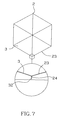
FIG. 7 corresponds to FIG. 5 but showing an alternate form of the light guide board.
FIG. 8 is a schematic drawing showing an application example of the present invention.
FIG. 9 is a schematic drawing showing another application example of the present invention.
DETAILED DESCRIPTION OF THE PREFERRED EMBODIMENT
Referring to FIGS. 1˜6, a lighting lamp 5 in accordance with a first embodiment of the present invention is shown comprising a cavity 11, a light guide board 2, and a set of LEDs (light emitting diodes) 4.
The cavity 11 may be directly formed in a lamp holder 1, a piece of furniture, a utensil, or the construction of a building.
The light guide board 2 is a polygonal member made of a high transmissive material and mounted inside the cavity 11, having a clear transmissive layer 21 at the front side and a continuous piece of reflective layer 3 at the back side. The reflective layer 3 has the shape of an umbrella surface, i.e., the surface of the reflective layer 3 slopes from the periphery toward the center 31.
In an example of the present invention, the light guide board 2 is a hexagonal member having an umbrella surface-like back surface 22 curved inwards at the back side, and the reflective layer 3 is directly covered on the umbrella surface-like back surface 22. The umbrella surface-like back surface 22 is divided into 6 equal smoothly curved triangularly shaped panels 23. The smoothly curved triangularly shaped panels 23 curves outwards and slopes downwardly toward the center 31 of the reflective layer 3. The inwardly curved back side design of the light guide board 2 diminishes material consumption.
The LEDs 4 are mounted within the cavity 11 outside the light guide board 2, and adapted to emit light through the light guide board 2 laterally.
As shown in FIGS. 1, 2 and 6, after installation of the lighting lamp 5, the LEDs 4 are turned on to emit light toward the inside of the light guide board 2 from two opposite lateral sides. When light rays go through the light guide board 2, the reflective layer 3 reflects light rays from the LEDs 4 toward the center of the light guide board 2, eliminating multi-image, enhancing the brightness, and simulating the lighting effect of a ball lamp.
Referring to FIG. 7, a downwardly extending narrow cut 24 is provided in between each two adjacent smoothly curved triangularly shaped panels 23, and the reflective layer 3 has a plurality of light blocking protruding portions 32 respectively engaged into the downwardly extending narrow cut 24 between each two adjacent smoothly curved triangularly shaped panels 23 to prevent dispersion of reflected light through the six peripheral sides.
Because the invention simulates the lighting effect of a ball lamp, it makes up for the shortcoming of the aforesaid two prior art designs, broadening the application range of the lighting fixture. In addition to the use as an embedded lamp, multiple lighting lamps 5 can be arranged in an array on a mounting board 6, forming a ceiling lamp assembly as shown in FIG. 8. FIG. 9 shows another application example of the present invention in which a frosted glass board 7 is provided in front of an array of lighting lamps 5 for use as a backlight module in a liquid crystal display screen.
Although particular embodiments of the invention have been described in detail for purposes of illustration, various modifications and enhancements may be made without departing from the spirit and scope of the invention. Accordingly, the invention is not to be limited except as by the appended claims.

Claims (12)

1. A lighting lamp comprising:
a cavity;
a light guide board mounted inside said cavity, said light guide board being a polygonal board made of a high transmissive material, said light guide board comprising a clear transmission layer at a front side thereof and a reflective layer covered on a back side thereof, said reflective layer having the shape of an umbrella surface and sloping from the periphery toward the center thereof;
a plurality of LEDs mounted within said cavity outside said light guide board and adapted to emit light laterally into the inside of said light guide board to provide a uniform lighting effect having an enhanced brightness without causing multi-image and to simulate the lighting effect of a ball lamp.
2. The lighting lamp as claimed in claim 1, wherein said reflective layer fits over the polygonal shape of said light guide board; said light guide board is divided into multiple smoothly curved triangularly shaped panels, said smoothly curved triangularly shaped panels curving outwards and sloping downwardly toward the center of said reflective layer.
3. The lighting lamp as claimed in claim 2, wherein said reflective layer comprises a plurality of downwardly extending light blocking protruding portions respectively engaged into a respective downwardly extending narrow cut between each two adjacent smoothly curved triangularly shaped panels of said light guide board.
4. A lighting lamp comprising:
a lamp holder, said lamp holder defining therein a cavity;
a light guide board mounted inside said cavity, said light guide board being a polygonal board made of a high transmissive material, said light guide board comprising a clear transmission layer at a front side thereof and a reflective layer covered on a back side thereof, said reflective layer having the shape of an umbrella surface and sloping from the periphery toward the center thereof;
a plurality of LEDs mounted within said cavity outside said light guide board and adapted to emit light laterally into the inside of said light guide board to provide a uniform lighting effect having an enhanced brightness without causing multi-image and to simulate the lighting effect of a ball lamp.
5. The lighting lamp as claimed in claim 4, wherein said reflective layer fits over the polygonal shape of said light guide board;
said light guide board is divided into multiple smoothly curved triangularly shaped panels, said smoothly curved triangularly shaped panels curving outwards and sloping downwardly toward the center of said reflective layer.
6. The lighting lamp as claimed in claim 5, wherein said reflective layer comprises a plurality of downwardly extending light blocking protruding portions respectively engaged into a respective downwardly extending narrow cut between each two adjacent smoothly curved triangularly shaped panels of said light guide board.
7. The lighting lamp as claimed in claim 4, wherein multiple lighting lamps are arranged in an array in a mounting board for use as a ceiling lighting fixture.
8. The lighting lamp as claimed in claim 4, wherein a frosted glass is provided in front of an array of multiple lighting lamps.
9. A lighting lamp comprising:
a lamp holder, said lamp holder defining therein a cavity;
a light guide board mounted inside said cavity, said light guide board being a hexagonal board made of a high transmissive material, said light guide board comprising a clear transmission layer at a front side thereof and a reflective layer at a back side thereof, said clear transmission layer having a back surface shaped like an umbrella surface and sloping from the periphery toward the center thereof, said reflective layer being covered on said umbrella-like back surface of said clear transmission layer, said umbrella surface-like back surface being divided into 6 smoothly curved triangularly shaped panel, said smoothly curved triangularly shaped panels curving outwards and sloping downwardly toward the center of said reflective layer; and
a plurality of LEDs mounted within said cavity outside said light guide board and adapted to emit light laterally into the inside of said light guide board to provide a uniform lighting effect having an enhanced brightness without causing multi-image and to simulate the lighting effect of a ball lamp.
10. The lighting lamp as claimed in claim 9, wherein said reflective layer comprises a plurality of downwardly extending light blocking protruding portions respectively engaged into a respective downwardly extending narrow cut between each two adjacent smoothly curved triangularly shaped panels of said light guide board.
11. The lighting lamp as claimed in claim 9, wherein multiple lighting lamps are arranged in an array in a mounting board for use as a ceiling lighting fixture.
12. The lighting lamp as claimed in claim 9, wherein a frosted glass is provided in front of an array of multiple lighting lamps.
US12/000,194 2007-12-10 2007-12-10 Lighting lamp Expired - Fee Related US7806581B2 (en)

Priority Applications (1)

Application Number Priority Date Filing Date Title
US12/000,194 US7806581B2 (en) 2007-12-10 2007-12-10 Lighting lamp

Applications Claiming Priority (1)

Application Number Priority Date Filing Date Title
US12/000,194 US7806581B2 (en) 2007-12-10 2007-12-10 Lighting lamp

Publications (2)

Publication Number Publication Date
US20100214771A1 US20100214771A1 (en) 2010-08-26
US7806581B2 true US7806581B2 (en) 2010-10-05

Family

ID=42630807

Family Applications (1)

Application Number Title Priority Date Filing Date
US12/000,194 Expired - Fee Related US7806581B2 (en) 2007-12-10 2007-12-10 Lighting lamp

Country Status (1)

Country Link
US (1) US7806581B2 (en)

Cited By (21)

* Cited by examiner, † Cited by third party
Publication number Priority date Publication date Assignee Title
US20110242806A1 (en) * 2010-03-31 2011-10-06 Renaissance Lighting, Inc. Solid state lighting with selective matching of index of refraction
US20110310603A1 (en) * 2010-06-16 2011-12-22 Abl Ip Holding Llc Light fixtures
US20140355302A1 (en) * 2013-03-15 2014-12-04 Cree, Inc. Outdoor and/or Enclosed Structure LED Luminaire for General Illumination Applications, Such as Parking Lots and Structures
US9291320B2 (en) 2013-01-30 2016-03-22 Cree, Inc. Consolidated troffer
US9366799B2 (en) 2013-03-15 2016-06-14 Cree, Inc. Optical waveguide bodies and luminaires utilizing same
US9366396B2 (en) 2013-01-30 2016-06-14 Cree, Inc. Optical waveguide and lamp including same
US9389367B2 (en) 2013-01-30 2016-07-12 Cree, Inc. Optical waveguide and luminaire incorporating same
US9411086B2 (en) 2013-01-30 2016-08-09 Cree, Inc. Optical waveguide assembly and light engine including same
US9442243B2 (en) 2013-01-30 2016-09-13 Cree, Inc. Waveguide bodies including redirection features and methods of producing same
US9625638B2 (en) 2013-03-15 2017-04-18 Cree, Inc. Optical waveguide body
US9645303B2 (en) 2013-03-15 2017-05-09 Cree, Inc. Luminaires utilizing edge coupling
US9690029B2 (en) 2013-01-30 2017-06-27 Cree, Inc. Optical waveguides and luminaires incorporating same
US9798072B2 (en) 2013-03-15 2017-10-24 Cree, Inc. Optical element and method of forming an optical element
US9869432B2 (en) 2013-01-30 2018-01-16 Cree, Inc. Luminaires using waveguide bodies and optical elements
US9920901B2 (en) 2013-03-15 2018-03-20 Cree, Inc. LED lensing arrangement
US10209429B2 (en) 2013-03-15 2019-02-19 Cree, Inc. Luminaire with selectable luminous intensity pattern
US10416377B2 (en) 2016-05-06 2019-09-17 Cree, Inc. Luminaire with controllable light emission
US10436970B2 (en) 2013-03-15 2019-10-08 Ideal Industries Lighting Llc Shaped optical waveguide bodies
US10502899B2 (en) * 2013-03-15 2019-12-10 Ideal Industries Lighting Llc Outdoor and/or enclosed structure LED luminaire
US11112083B2 (en) 2013-03-15 2021-09-07 Ideal Industries Lighting Llc Optic member for an LED light fixture
US11719882B2 (en) 2016-05-06 2023-08-08 Ideal Industries Lighting Llc Waveguide-based light sources with dynamic beam shaping

Citations (2)

* Cited by examiner, † Cited by third party
Publication number Priority date Publication date Assignee Title
US20050180167A1 (en) * 2002-03-28 2005-08-18 Hoelen Christoph G.A. Compact lighting system and display device
US20090086507A1 (en) * 2007-09-28 2009-04-02 Fujifilm Corporation Planar lighting device

Patent Citations (2)

* Cited by examiner, † Cited by third party
Publication number Priority date Publication date Assignee Title
US20050180167A1 (en) * 2002-03-28 2005-08-18 Hoelen Christoph G.A. Compact lighting system and display device
US20090086507A1 (en) * 2007-09-28 2009-04-02 Fujifilm Corporation Planar lighting device

Cited By (32)

* Cited by examiner, † Cited by third party
Publication number Priority date Publication date Assignee Title
US20110242806A1 (en) * 2010-03-31 2011-10-06 Renaissance Lighting, Inc. Solid state lighting with selective matching of index of refraction
US8322884B2 (en) * 2010-03-31 2012-12-04 Abl Ip Holding Llc Solid state lighting with selective matching of index of refraction
US20110310603A1 (en) * 2010-06-16 2011-12-22 Abl Ip Holding Llc Light fixtures
US9823408B2 (en) 2013-01-30 2017-11-21 Cree, Inc. Optical waveguide and luminaire incorporating same
US9389367B2 (en) 2013-01-30 2016-07-12 Cree, Inc. Optical waveguide and luminaire incorporating same
US9869432B2 (en) 2013-01-30 2018-01-16 Cree, Inc. Luminaires using waveguide bodies and optical elements
US9366396B2 (en) 2013-01-30 2016-06-14 Cree, Inc. Optical waveguide and lamp including same
US11644157B2 (en) 2013-01-30 2023-05-09 Ideal Industries Lighting Llc Luminaires using waveguide bodies and optical elements
US9411086B2 (en) 2013-01-30 2016-08-09 Cree, Inc. Optical waveguide assembly and light engine including same
US9442243B2 (en) 2013-01-30 2016-09-13 Cree, Inc. Waveguide bodies including redirection features and methods of producing same
US9519095B2 (en) 2013-01-30 2016-12-13 Cree, Inc. Optical waveguides
US9581751B2 (en) 2013-01-30 2017-02-28 Cree, Inc. Optical waveguide and lamp including same
US10436969B2 (en) 2013-01-30 2019-10-08 Ideal Industries Lighting Llc Optical waveguide and luminaire incorporating same
US9690029B2 (en) 2013-01-30 2017-06-27 Cree, Inc. Optical waveguides and luminaires incorporating same
US9291320B2 (en) 2013-01-30 2016-03-22 Cree, Inc. Consolidated troffer
US20140355302A1 (en) * 2013-03-15 2014-12-04 Cree, Inc. Outdoor and/or Enclosed Structure LED Luminaire for General Illumination Applications, Such as Parking Lots and Structures
US9645303B2 (en) 2013-03-15 2017-05-09 Cree, Inc. Luminaires utilizing edge coupling
US9798072B2 (en) 2013-03-15 2017-10-24 Cree, Inc. Optical element and method of forming an optical element
US10168467B2 (en) 2013-03-15 2019-01-01 Cree, Inc. Luminaires utilizing edge coupling
US9366799B2 (en) 2013-03-15 2016-06-14 Cree, Inc. Optical waveguide bodies and luminaires utilizing same
US10209429B2 (en) 2013-03-15 2019-02-19 Cree, Inc. Luminaire with selectable luminous intensity pattern
US10379278B2 (en) * 2013-03-15 2019-08-13 Ideal Industries Lighting Llc Outdoor and/or enclosed structure LED luminaire outdoor and/or enclosed structure LED luminaire having outward illumination
US10502899B2 (en) * 2013-03-15 2019-12-10 Ideal Industries Lighting Llc Outdoor and/or enclosed structure LED luminaire
US10436970B2 (en) 2013-03-15 2019-10-08 Ideal Industries Lighting Llc Shaped optical waveguide bodies
US9625638B2 (en) 2013-03-15 2017-04-18 Cree, Inc. Optical waveguide body
US9920901B2 (en) 2013-03-15 2018-03-20 Cree, Inc. LED lensing arrangement
US11112083B2 (en) 2013-03-15 2021-09-07 Ideal Industries Lighting Llc Optic member for an LED light fixture
US10890714B2 (en) 2016-05-06 2021-01-12 Ideal Industries Lighting Llc Waveguide-based light sources with dynamic beam shaping
US10527785B2 (en) 2016-05-06 2020-01-07 Ideal Industries Lighting Llc Waveguide-based light sources with dynamic beam shaping
US11372156B2 (en) 2016-05-06 2022-06-28 Ideal Industries Lighting Llc Waveguide-based light sources with dynamic beam shaping
US11719882B2 (en) 2016-05-06 2023-08-08 Ideal Industries Lighting Llc Waveguide-based light sources with dynamic beam shaping
US10416377B2 (en) 2016-05-06 2019-09-17 Cree, Inc. Luminaire with controllable light emission

Also Published As

Publication number Publication date
US20100214771A1 (en) 2010-08-26

Similar Documents

Publication Publication Date Title
US7806581B2 (en) Lighting lamp
US8888316B2 (en) Lenticular LED light source replacement for fluorescent in troffer
US7963689B2 (en) LED-edgelit light guide fixture having LED receiving grooves
TWI522571B (en) Illumination apparatus
JP2008542994A (en) Backlight assembly and display device having the same
US20110222294A1 (en) Side emitting LED module
TWI522572B (en) Illumination apparatus
US7470054B2 (en) Light-guide board
EP2056136B1 (en) Lighting Lamp
US20110310625A1 (en) Light Fixtures Comprising Organic Light Emitting Diodes
CN103388773A (en) Solar spectrum type LED (Light-Emitting Diode) eye protection panel lamp/panel desk lamp
US20130170198A1 (en) Lamp structure capable of switching light-emitting mode
TWI392125B (en) Light emitting device
TW201500691A (en) Lens, light source device incorporating the same and light source module incorporating the same
CN202580846U (en) Direct-lighting type LED (light-emitting diode) area source
US20130135853A1 (en) Light-guiding element, light-emitting diode lamp tube and illumination lamp
JP3139278U (en) Lighting apparatus and lighting apparatus using the same
KR20130029865A (en) Led advertising plate for front and rear light
CN202834837U (en) Light emitting diode (LED) fluorescent lamp
CN202852574U (en) A solar spectrum-type eye-protecting LED panel lamp or panel desk lamp
CN101661184B (en) Display device
CN201663174U (en) Led
KR20170011948A (en) Refraction lens and plate-form structure which has multiple refraction lenses extending therethrough
CA2593294C (en) Light-guide board
CN204387924U (en) A kind of solar lawn lamp

Legal Events

Date Code Title Description
AS Assignment

Owner name: KUN DIAN PHOTOELECTRIC ENTERPRISE CO., TAIWAN

Free format text: ASSIGNMENT OF ASSIGNORS INTEREST;ASSIGNOR:LEE, CHENG SHENG;REEL/FRAME:020271/0762

Effective date: 20071110

FPAY Fee payment

Year of fee payment: 4

FEPP Fee payment procedure

Free format text: MAINTENANCE FEE REMINDER MAILED (ORIGINAL EVENT CODE: REM.)

LAPS Lapse for failure to pay maintenance fees

Free format text: PATENT EXPIRED FOR FAILURE TO PAY MAINTENANCE FEES (ORIGINAL EVENT CODE: EXP.); ENTITY STATUS OF PATENT OWNER: SMALL ENTITY

STCH Information on status: patent discontinuation

Free format text: PATENT EXPIRED DUE TO NONPAYMENT OF MAINTENANCE FEES UNDER 37 CFR 1.362

FP Expired due to failure to pay maintenance fee

Effective date: 20181005