US7806535B2 - Low power projection display devices - Google Patents
Low power projection display devices Download PDFInfo
- Publication number
- US7806535B2 US7806535B2 US11/741,499 US74149907A US7806535B2 US 7806535 B2 US7806535 B2 US 7806535B2 US 74149907 A US74149907 A US 74149907A US 7806535 B2 US7806535 B2 US 7806535B2
- Authority
- US
- United States
- Prior art keywords
- display device
- light
- base
- battery
- projection
- Prior art date
- Legal status (The legal status is an assumption and is not a legal conclusion. Google has not performed a legal analysis and makes no representation as to the accuracy of the status listed.)
- Active, expires
Links
- 230000003287 optical effect Effects 0.000 claims description 128
- 239000000835 fiber Substances 0.000 claims description 19
- 238000000034 method Methods 0.000 claims description 17
- 238000001816 cooling Methods 0.000 claims description 8
- 238000013461 design Methods 0.000 abstract description 42
- 230000033001 locomotion Effects 0.000 description 22
- 238000004891 communication Methods 0.000 description 16
- 230000008878 coupling Effects 0.000 description 16
- 238000010168 coupling process Methods 0.000 description 16
- 238000005859 coupling reaction Methods 0.000 description 16
- 230000005540 biological transmission Effects 0.000 description 15
- 230000008569 process Effects 0.000 description 14
- 239000004033 plastic Substances 0.000 description 11
- 239000003818 cinder Substances 0.000 description 9
- 229910052751 metal Inorganic materials 0.000 description 9
- 239000002184 metal Substances 0.000 description 9
- 229910052782 aluminium Inorganic materials 0.000 description 8
- XAGFODPZIPBFFR-UHFFFAOYSA-N aluminium Chemical compound [Al] XAGFODPZIPBFFR-UHFFFAOYSA-N 0.000 description 8
- 230000004907 flux Effects 0.000 description 8
- 239000000463 material Substances 0.000 description 7
- 230000004044 response Effects 0.000 description 6
- 230000008901 benefit Effects 0.000 description 5
- 230000033228 biological regulation Effects 0.000 description 5
- 230000008859 change Effects 0.000 description 5
- 230000007423 decrease Effects 0.000 description 5
- 238000006243 chemical reaction Methods 0.000 description 4
- 230000003247 decreasing effect Effects 0.000 description 4
- 238000005516 engineering process Methods 0.000 description 4
- 239000004973 liquid crystal related substance Substances 0.000 description 4
- 239000002991 molded plastic Substances 0.000 description 4
- 238000003860 storage Methods 0.000 description 4
- 230000001413 cellular effect Effects 0.000 description 3
- 239000013307 optical fiber Substances 0.000 description 3
- 238000012546 transfer Methods 0.000 description 3
- 210000003857 wrist joint Anatomy 0.000 description 3
- HBBGRARXTFLTSG-UHFFFAOYSA-N Lithium ion Chemical compound [Li+] HBBGRARXTFLTSG-UHFFFAOYSA-N 0.000 description 2
- 201000009310 astigmatism Diseases 0.000 description 2
- 239000003086 colorant Substances 0.000 description 2
- 238000010276 construction Methods 0.000 description 2
- 238000012937 correction Methods 0.000 description 2
- 238000006073 displacement reaction Methods 0.000 description 2
- 230000009977 dual effect Effects 0.000 description 2
- 230000006870 function Effects 0.000 description 2
- 229910052736 halogen Inorganic materials 0.000 description 2
- 150000002367 halogens Chemical class 0.000 description 2
- 230000017525 heat dissipation Effects 0.000 description 2
- 230000020169 heat generation Effects 0.000 description 2
- 230000003993 interaction Effects 0.000 description 2
- 229910001416 lithium ion Inorganic materials 0.000 description 2
- 238000007726 management method Methods 0.000 description 2
- 238000004519 manufacturing process Methods 0.000 description 2
- 230000013011 mating Effects 0.000 description 2
- 238000012986 modification Methods 0.000 description 2
- 230000004048 modification Effects 0.000 description 2
- 238000004806 packaging method and process Methods 0.000 description 2
- 230000001681 protective effect Effects 0.000 description 2
- 230000009467 reduction Effects 0.000 description 2
- 230000002829 reductive effect Effects 0.000 description 2
- 230000001105 regulatory effect Effects 0.000 description 2
- 238000007493 shaping process Methods 0.000 description 2
- 230000003068 static effect Effects 0.000 description 2
- 230000000007 visual effect Effects 0.000 description 2
- 206010034960 Photophobia Diseases 0.000 description 1
- 239000000853 adhesive Substances 0.000 description 1
- 230000001070 adhesive effect Effects 0.000 description 1
- 238000003491 array Methods 0.000 description 1
- 230000000712 assembly Effects 0.000 description 1
- 238000000429 assembly Methods 0.000 description 1
- 238000005452 bending Methods 0.000 description 1
- 230000015572 biosynthetic process Effects 0.000 description 1
- 238000005266 casting Methods 0.000 description 1
- 239000002131 composite material Substances 0.000 description 1
- 238000009429 electrical wiring Methods 0.000 description 1
- 238000005286 illumination Methods 0.000 description 1
- 230000002452 interceptive effect Effects 0.000 description 1
- 238000005304 joining Methods 0.000 description 1
- 208000013469 light sensitivity Diseases 0.000 description 1
- 239000000203 mixture Substances 0.000 description 1
- 230000000737 periodic effect Effects 0.000 description 1
- 238000012545 processing Methods 0.000 description 1
- 230000001902 propagating effect Effects 0.000 description 1
- 238000011160 research Methods 0.000 description 1
- 230000000284 resting effect Effects 0.000 description 1
- 230000035945 sensitivity Effects 0.000 description 1
- 230000001360 synchronised effect Effects 0.000 description 1
- 230000007704 transition Effects 0.000 description 1
- 238000011144 upstream manufacturing Methods 0.000 description 1
- 210000000707 wrist Anatomy 0.000 description 1
Images


Classifications
-
- G—PHYSICS
- G03—PHOTOGRAPHY; CINEMATOGRAPHY; ANALOGOUS TECHNIQUES USING WAVES OTHER THAN OPTICAL WAVES; ELECTROGRAPHY; HOLOGRAPHY
- G03B—APPARATUS OR ARRANGEMENTS FOR TAKING PHOTOGRAPHS OR FOR PROJECTING OR VIEWING THEM; APPARATUS OR ARRANGEMENTS EMPLOYING ANALOGOUS TECHNIQUES USING WAVES OTHER THAN OPTICAL WAVES; ACCESSORIES THEREFOR
- G03B21/00—Projectors or projection-type viewers; Accessories therefor
- G03B21/14—Details
- G03B21/16—Cooling; Preventing overheating
-
- H—ELECTRICITY
- H04—ELECTRIC COMMUNICATION TECHNIQUE
- H04N—PICTORIAL COMMUNICATION, e.g. TELEVISION
- H04N9/00—Details of colour television systems
- H04N9/12—Picture reproducers
- H04N9/31—Projection devices for colour picture display, e.g. using electronic spatial light modulators [ESLM]
- H04N9/3141—Constructional details thereof
-
- G—PHYSICS
- G03—PHOTOGRAPHY; CINEMATOGRAPHY; ANALOGOUS TECHNIQUES USING WAVES OTHER THAN OPTICAL WAVES; ELECTROGRAPHY; HOLOGRAPHY
- G03B—APPARATUS OR ARRANGEMENTS FOR TAKING PHOTOGRAPHS OR FOR PROJECTING OR VIEWING THEM; APPARATUS OR ARRANGEMENTS EMPLOYING ANALOGOUS TECHNIQUES USING WAVES OTHER THAN OPTICAL WAVES; ACCESSORIES THEREFOR
- G03B21/00—Projectors or projection-type viewers; Accessories therefor
- G03B21/005—Projectors using an electronic spatial light modulator but not peculiar thereto
Definitions
- This invention relates to display devices that project an image. More particularly, the present invention relates to projection-type display devices that may operate on battery power and increase usage flexibility.
- Most computer systems employ a display device to output video information to one or more users.
- Desktop computers, laptop computers, personal digital assistants (PDAs), video game consoles, cellular telephones and digital video cameras output video information to a number of video display technologies.
- PDAs personal digital assistants
- video game consoles video game consoles
- cellular telephones cellular telephones
- digital video cameras output video information to a number of video display technologies.
- Projection-type display systems offer image sizes having diagonal spans up to 30 feet. Projected images allow numerous people to simultaneously view a projected image.
- the present invention relates to devices that provide projection-type video output in a portable design.
- the projection-type display device includes a battery that stores electrical energy.
- the battery increases display device portability and flexible usage by permitting display device operation in locations not serviceable by a fixed power supply.
- the present invention may also implement one or more hardware designs that reduce power consumption.
- the positional interface is coupled to the base and coupled to the projection chamber; and allows the projection chamber to be moved relative to the base and allows the projection chamber to maintain a constant position relative to the base after being moved.
- the electrical energy transport system is configured to transmit electrical energy from the battery to the light source and to transmit electrical energy from the battery to the optical modulation device.
- FIG. 3B shows a front view illustration of the display device of FIG. 1 with the positional interface and lower projection chamber cutaway to show components therein in accordance with one embodiment of the present invention.
- FIG. 4B illustrates a cutaway front view of a display device and a ball and socket positional interface in accordance with another embodiment of the present invention.
- FIG. 5A illustrates a process flow for projecting video output from a display device in accordance with one embodiment of the invention.
- FIG. 6C illustrates a front view of the display device base of FIG. 6A with the bendable tubing removed to show the portions of the base for the receiving tubing.
- Projection type display devices of the present invention include a battery that stores electrical energy for powering electrical components within the display device.
- the battery permits display device usage in areas and applications removed from a fixed power supply.
- inclusion of a battery extends projector-type display device usage into a car, library, coffee shop, remote environment, or any other setting where AC and fixed power outlets are not readily available or within power cord reach.
- research and military personnel operating in the field may benefit from portable display opportunities awarded by the present invention.
- battery-based designs described herein permit operation of display devices in rooms and large spaces in locations far removed from a fixed power supply.
- Base 12 is configured to maintain the position of display device 10 , e.g., relative to a stationary object.
- base 12 includes a relatively flat bottom that allows display device 10 to rest upon a flat surface such as a table or desk.
- One or more high friction pads 18 attach to a bottom surface 22 b of base 12 to increase static friction with the flat surface.
- Base 12 may also comprise a receiving slot 27 that allows modular attachment of functional accessories for display device 10 .
- slot 27 may receive a clip attachment that comprises a spring-powered clip for clamping base 12 onto a stationary object. This allows base 12 and display device 10 to be mounted on non-flat or non-horizontal surfaces such as vertical walls of bookshelves and cubicles, and personal clothing or accessories such as belts or straps, for example.
- Base 12 may also comprise another slot on its bottom side, dimensioned the same, to permit reception of the functional accessories on the bottom side of base 12 .
- Projection chamber 14 includes components responsible for the production of images based on received light and received video data, and components responsible for the projection of those images.
- Projection chamber 14 comprises a projection chamber housing 32 , an optical modulation device, and an output projection lens system.
- the optical modulation device selectively transmits light generated by a light source in base 12 according to video data included in a video signal provided to the optical modulation device, and will be described in further detail with respect to FIG. 3A .
- the projection lens system outputs light transmitted by the optical modulation device along a projection path 31 , and will also be described in further detail with respect to FIG. 3A .
- a light source within base 12 generates light which is provided to the optical modulation device within projection chamber 14 as a luminous flux.
- one or more optical fibers transmit light from the light source within base 12 to the optical modulation device within projection chamber 14 .
- the optical modulation device selectively transmits light according to video data in a signal that corresponds to an image to be projected.
- the projection lens system enlarges and projects an image formed by the optical modulation device. Typically, the image is cast with a splay angle such that the image enlarges as the distance to a receiving surface increases.
- a receiving interface 29 is disposed on the lower side of projection chamber 14 and permits coupling between projection chamber 14 and positional interface 16 .
- Interface 29 also permits containment and protection of display device 10 components that do not entirely fit within projection chamber 14 , or components that require spatial arrangements outside of projection chamber 14 .
- interface 29 comprises the same material as housing 32 and extends the interior projection chamber provided by housing 32 .
- upper end 16 b of positional interface 16 couples at a location relatively close to a center of mass 25 of projection chamber 14 to minimize mechanical moments transmitted onto base 12 , e.g., those resulting from a displacement of center of mass 25 away from a center of mass 23 for base 12 .
- base 12 includes a recessed groove in top wall 22 a that allows positional interface 16 to be folded or collapsed down into top wall 22 a , thereby decreasing the profile of display device 10 during non-use.
- FIG. 2A shows a simplified top view schematic 50 of components within base 12 in accordance with one embodiment of the present invention.
- a light source chamber 65 is defined in volume and shape by inside walls 22 a - f of base 12 .
- Light source chamber 65 comprises fans 62 , light source 64 , power supply 66 , fiber-optic interface 70 , fiber-optic 72 , input output circuitry 74 , control circuitry 76 , and input/output interfaces 78 .
- Fans 62 a and 62 b move air through light source chamber 65 for cooling components within light source chamber 65 .
- fans 62 draw air in through inlet air vents 24 a on one side of base 12 and exhaust heated air out of exhaust air vents 24 b after the air has cooled internal components of base 12 and walls of housing 20 .
- fan 62 and vent 24 placement will vary with internal component placement within light source chamber 65 .
- fan 62 placement—and airflow patterns effected by fans 62 within light source chamber 65 is designed according to individual temperature regulation requirements and heat generation contributions of components within base 12 .
- Display device 10 may employ a number of light generating technologies and configurations for generating light, each of which includes its own set and arrangement of light generation and light manipulation components. In one embodiment, display device 10 comprises diode lasers for light generation and consumes less than about 50 watts when outputting a projected image.
- FIGS. 2B and 2C illustrate simplified front and top perspective views, respectively, of a light source configuration in accordance with another embodiment of the present invention.
- light source chamber 65 includes an array of lasers 96 that generate collimated light.
- Lasers 96 may comprise diode lasers and diode pumped solid-state (DPSS) lasers, for example.
- the collimated light produced by a diode laser differs from radiant light and is characterized by light that is output with about the same output direction, and significantly in phase.
- the array of lasers may comprise one or more red diode lasers 96 a or red DPSS lasers 96 a , one or more green DPSS lasers 96 b , and one or more blue diode lasers 96 c or blue DPSS lasers 96 c .
- the number and power of lasers for each color is scaled according to a desired light intensity output for display device 10 and according to the light sensitivity of a viewer to each color, as one skilled in the art will appreciate.
- Each laser 96 is installed on a circuit board 97 , which mounts, and provides electrical control for, each laser 96 installed thereon. Multiple lasers 96 may be mounted on a single board 97 to reduce space occupied by light source 64 .
- cabling 72 may be bent and flexibly positioned, cabling 72 advantageously allows light transmission between lasers 96 and relay optics system regardless of the positioning and orientation between the lasers and optics system. For example, this allows flexible arrangement of lasers 96 , relay optics 106 and 108 and prism 110 ( FIG. 3A ), which may be used to improve space conservation within base 12 , decrease the footprint of base 12 , and minimize display device 10 size.
- flexible fiber-optic cabling 72 also allows positional interface 16 to move without compromising light provision to the optical modulation device in projection chamber 14 .
- the number of fiber optic cables in cabling 72 will vary with design. Multiple fiber-optic cables 72 may be employed in a design where each cable 72 services one or more lasers. As shown in FIG. 2D , light from each laser 96 is first transmitted into a fiber-optic cable 72 dedicated to each laser; and subsequently routed and transmitted into a common fiber-optic cable 71 . Each laser dedicated fiber-optic cable 72 thus receives laser light from an individual laser 96 , and transmits the light to junction 75 . In one embodiment, each fiber-optic cable 72 attaches directly to an individual laser 96 .
- each fiber-optic cable 72 may include a fixture with an inner threaded interface that matches a threaded interface disposed on an outside surface of a diode laser 96 housing.
- Commercially available fiber-optic cables such as that available from Ocean Optics Inc. of Dunedin, Fla., may come standard with such coupling and alignment fixtures.
- a short focal length normal or GRIN lens is mounted at the inlet end of each cable 72 to facilitate laser-to-fiber light transition and collimated transfer into cable 72 .
- junction 75 permits transmission of light from fiber-optic cables 72 into converging optics 77 , and into common fiber-optic cable 79 .
- Converging optics 77 redirect incoming light from each fiber-optic cable 72 into common fiber-optic cable 79 and comprise a converging lens 77 a that redirects light toward re-collimating lens 77 b , which collimates and re-directs incoming laser light from converging lens 77 a into common optical fiber 79 .
- junction 75 may also include a rigid structure, such as a suitably dimensioned molded plastic, that fixtures (holds and positions) fiber-optic cables 72 and 79 .
- junction 75 comprises an optical adhesive that adheres cables 72 directly to lens 77 a .
- the outlet end 72 b the fiber-optic cables 72 are combined into a larger cable 71 that contains multiple fibers.
- Multiple fiber cables, such as fiber ribbon-based cables and those that employ multiple fibers located circumferentially within a round tube, are commercially available from a variety of vendors.
- Fiber-optic cable designs may be employed where each cable transmits a primary color.
- three fiber-optic cables may be employed in which each cable transmits light from a primary color set of lasers along three different optical paths to three primary color dedicated optical modulation devices.
- a common fiber-optic cable may be used to transmit sequentially emitted red, green and blue light along a common light path to a single mirror-based optical modulation device 44 .
- Fiber-optic cabling 72 may comprise single mode or multimode fibers such as those readily available from a wide variety of vendors known to those skilled in the art.
- a converging lens is disposed at outlet end 72 b when fiber-optic cable 72 is a single mode fiber to correct for any divergence resulting from light transmission within the single mode fiber-optic cable 72 .
- diode lasers for light generation each output relatively monochromatic colored light, thereby eliminating the need for a color wheel and its associated spatial requirement; and eliminating the color wheel motor which also occupies space, consumes power and generates heat.
- the highly collimated and smaller cross-sectional area laser output needs less space and smaller optics for cross-sectional area manipulation than light output by a lamp, saving significant space that would otherwise be required for larger light condensing lenses and their required focal lengths for condensing of light generated by a white light lamp.
- frame and color sequential information output by a diode laser light generation system can be digitally synchronized faster and with greater precision than with a mechanical color wheel system.
- Output lenses for each diode laser may also include custom shaping that corrects for any astigmatism and divergence provided by the diode laser generator. Further description of astigmatism and divergence correcting lenses are described in commonly owned and patent application entitled “PROJECTION-TYPE DISPLAY DEVICES WITH REDUCED WEIGHT AND SIZE”, which was incorporated by reference above.
- inner light chamber 65 may also employ other light source arrangements to generate light for display device 10 .
- Some light source arrangements may comprise an array of radiant light emitting diodes (characterized by radiant, non-lasing or non-collimated light generation). Similar to diode and DPSS lasers, radiant light emitting diodes consume less power and generate less heat than a white light lamp, and also emit colored light and thereby may operate without a color wheel.
- Light chamber 65 may also include one or more dichroic mirrors in white light generation assemblies to separate red, green and blue light for transmission within fiber optic cables 72 to color dedicated optical modulation devices, such as three liquid crystal display (LCD) valves employed for red, green and blue control.
- LCD liquid crystal display
- At least one battery 66 is included in housing 32 to store electrical energy.
- An electrical energy transport system 71 is in electrical communication with battery 66 and with various components within display device 10 ; and transfers electrical energy from battery 66 to the various components.
- electrical energy transport system 71 includes electrical communication 71 a between battery 66 and light source 64 and electrical communication 71 b between battery 66 and the optical modulation device 102 in projection chamber 14 .
- battery 66 is rechargeable.
- a lithium ion battery is suitable for use as battery 66 .
- Lithium ion batteries are widely available from a variety of vendors that are well known in the art, such as those that supply the laptop computer market.
- Battery 66 may be recharged using power provided through inlet port 81 .
- Battery 66 allows display device 10 to operate on stored energy and without reliance on proximity to an AC power source, which further increases portability of display device 10 .
- An electrical energy transport system 71 is in electrical communication with battery 66 and with various components within display device 10 ; and transfers electrical energy from battery 66 to the various components.
- electrical energy transport system 71 includes electrical communication 71 a between battery 66 and light source 64 and electrical communication 71 b between battery 66 and the optical modulation device 102 in projection chamber 14 .
- Electrical energy transport system 71 includes one or more wires, electrical connectors, pinned and multiple line electrical cables, printed circuit board circuits, switches to control current flow, etc.
- Electrical communication 71 b for example, comprises one or more electrical connectors that travel through positional interface 16 from base 12 to projection chamber 14 , as will be described in further detail below with respect to FIGS. 4A-4F .
- Electrical energy transport system 71 is thus configured to deliver electrical energy from the battery to the light source and to transmit electrical energy from the battery to the optical modulation device.
- Other components having electrical communication with battery 66 through system 71 include control circuitry 76 , input/output circuitry 74 , fans 62 , power diode 80 .
- Inlet power port 81 receives a power cord, which electrically couples display device 10 to an AC power source such as a wall power supply.
- the power cord comprises a transformer that converts AC electrical power to DC electrical power before receipt of the DC power by the display device at the inlet power port 81 .
- conversion of AC power to DC power occurs in a transformer included between ends of the power cord, as is common with many laptop computer power cords; thereby reducing the size of power supply 66 , base 12 and display device 10 and increasing portability of display device 10 .
- Power circuitry 87 converts incoming power from the power cord to one or more DC voltages used within display device 10 to allow display device 10 to run from a fixed power supply when battery 66 is not used.
- power circuitry 87 is also recharges battery 66 when the power cord provides power to port 81 .
- At least one fiber-optic cable 72 transmits light from light source 64 to relay optics ( FIG. 3A ) disposed along a light path between an exit end of fiber-optic cable 72 and an optical modulation device ( FIG. 3A ) in projection chamber 14 .
- fiber-optic cable 72 transmits light from one compartment to a separate compartment, namely, from light source chamber in base 12 to projection chamber 14 .
- the number of fiber optic cables will vary with design. As mentioned above, multiple fiber-optic cables may be employed in a laser light generation design, for example, where each cable 72 services one or more diode lasers. Alternatively, each cable 72 may service a primary color. One or more fiber-optic cables 72 may also be used to transmit light from a lamp.
- one fiber-optic cable may be used to transmit sequentially controlled red, green and blue generated by a diode laser array and transmitted along a single light path to a single mirror-based optical modulation device.
- Three fiber-optic cables may be employed to transmit light from a) a single lamp that outputs white light which is subsequently separated into three primary colors, or b) a laser array that outputs red, green and blue light into three fiber-optic cables, to three optical modulation devices that are each dedicated to modulation of a primary color.
- Fiber optic interface 70 facilitates transmission of light from each laser into fiber-optic cabling 72 ( FIG. 2A ).
- Interface 70 may include one or more fixtures that position and hold an inlet end for each fiber-optic cable included in cabling 72 such that light output from the light source transmits into a fiber-optic cable.
- Interface 70 may also include optics that direct light from lasers into cabling 72 .
- a single fiber-optic cable is used in cabling 72 and fiber optic interface 70 includes a lens system disposed between the outlet of a lamp or each laser and the inlet of the single fiber-optic cable to direct light into the cable.
- the lens system may comprise at least two lenses: a first lens to direct the light towards the fiber entrance and a second lens that collimates light entering the cable.
- fiber optic interface 70 holds the inlet end for each fiber-optic cable 72 relatively close to the outlet of each laser to receive light therefrom.
- Each cable in this case may include a converging lens at its inlet end that facilitates light capture and transmission into a cable.
- each fiber-optic cable in cabling 72 includes a fixture that permits attachment to another object.
- conventionally available fiber-optic cables available from vendors such as Ocean Optics Inc. of Dunedin, Fla. include a detachable fixture with a thread that allows screwing and fixing of the fiber-optic cable to a mating thread disposed on a laser housing.
- fiber-optic interface 70 comprises the threaded fixture from each cable and the mating thread on the laser.
- Control circuitry 76 provides control signals to components within base 12 and routes data from input/output circuitry 74 to appropriate components within display device 10 .
- control circuitry 76 provides control signals to light source 64 that determine when light source 64 is turned on/off.
- circuitry 76 may include and access memory that stores instructions for the operation of components within display device 10 .
- circuitry 74 may provide control signals to control fans 24 according to stored heat regulation instructions.
- One or more sensors may also be disposed within base 12 to facilitate thermal regulation.
- a temperature sensor may be disposed proximate to circuitry 74 and 76 to monitor temperature levels and participate in closed loop temperature control within base 12 as controlled by control circuitry 76 .
- Input/output circuitry 74 and input ports 78 collectively permit communication between display device 10 and a device that outputs a video signal carrying video data.
- a device that outputs a video signal carrying video data.
- desktop computers, laptop computers, personal digital assistants (PDAs), cellular telephones, video game consoles, digital cameras, digital video recorders, DVD players, and VCRs may all be suitable to output video data to display device 10 .
- Video data provided to control circuitry 76 may be in an analog or digital form.
- input/output circuitry 74 and control circuitry 76 convert analog video signals into digital video signals suitable for digital control of an optical modulation device included in display device 10 , such as a liquid crystal display “LCD” device or a digital micromirror “DMD” device.
- LCD liquid crystal display
- DMD digital micromirror
- input/output circuitry 74 or control circuitry 76 may also include support software and logic for particular connector types, such as processing logic required for S-video cabling or a digital video signal.
- Control circuitry 76 may also include and access memory that facilitates conversion of incoming data types and enhances video compatibility of display device 10 .
- Suitable video formats having stored conversion instructions within memory accessed by control circuitry 76 may include NTSC, PAL, SECAM, EDTV, and HDTV (1080i and 720p RGBHV), for example.
- Power diode 80 ( FIG. 2A ) is electrical communication with an external power switch 82 ( FIG. 1 ) and illuminates when display device 10 is turned on to indicate whether display device 10 is on or off.
- FIG. 3A shows a simplified side view illustration of components within projection chamber 14 of FIG. 1 , taken through a vertical midpoint of chamber 14 along its cylindrical axis, in accordance with one embodiment of the present invention.
- FIG. 3B shows a front view illustration of display device 10 with positional interface 16 and lower projection chamber 29 cutaway to show components therein.
- Projection chamber 14 comprises optical modulation device 102 , fiber-optic interface 104 , relay optics 106 and 108 , prism structure 110 , projection lens system 112 , control and power cabling 120 , and air duct 122 .
- Fiber-optic cable 72 attaches to a fiber-optic interface 104 and outputs light to relay optics 106 .
- fiber-optic interface 104 secures fiber-optic cable 72 such that slack is provided for fiber-optic cable between attachment at fiber-optic interface 104 and attachment within base 12 .
- the slack allows fiber-optic cable 72 to deflect with positional interface 16 for various positions of projection chamber 14 relative to base 12 .
- fiber-optic cable 72 and fiber-optic interface 104 direct light generated by light source 64 to prism 110 .
- fiber-optic cable 72 and interface 104 are configured with respect to prism 110 so as to provide an optical path of incident light that is about perpendicular to an incident surface of prism 110 .
- Some digital micromirror light modulator designs require that incoming light be incident on the light modulator from either above or below its light reflecting surface to allow light output along output path 31 .
- Relay optics 106 and 108 convert light receive from fiber-optic cable 72 to light suitable for transmission into prism structure 110 and onto optical modulation device 102 . This may include shaping and resizing light flux received from cable 72 using one or more lenses.
- light source 64 comprises a lamp 91 and uses a downstream optical integrator 95 as illustrated in FIG. 2B
- lens 106 is selected and arranged within interface 29 of projection chamber 14 to increase the area of light flux received from fiber-optic cable 72 .
- Lens 108 is then selected and arranged to convert the divergent light transmitted by lens 106 into substantially parallel flux for transmission into prism 110 and onto optical modulation device 102 .
- display device 10 comprises a pair of fly-eye lenses arranged in the optical path between light source 64 and prism 110 . Cumulatively, the pair of fly-eye lenses uniformly distribute light received from fiber-optic cable 72 to the flux transmitted upon optical modulation device 102 . In a specific embodiment, the pair of fly-eye lenses are arranged on either and a fiber-optic cable 72 .
- the first fly-eye lens is disposed at fiber-optic interface 70 within base 12 , receives light from a lamp or diode laser array, and spatially divides the entire input light flux into a set of blocks or components that each comprise a portion of the total area of the inlet flux. Light for each block or component then travels down its own fiber-optic cable 72 .
- the second fly-eye lens comprises the same number of blocks or components and is disposed at relay lens 106 .
- the second fly-eye lens receives a fiber-optic cable for each block or component, and outputs light for each component such that the light from each component is expanded to span the downstream dimensions of optical modulation device 102 and the projected image.
- Prism structure 110 is an optical modulation system that provides light to optical modulation device 102 at predetermined angles. Prism structure 110 also transmits light from optical modulation device 102 to the projection lens system 112 along output path 31 .
- Prism structure 110 comprises prism components 110 a and 110 b that are separated by air space or bonding interface 110 c .
- Interface 110 c is disposed at such an angle so as to reflect light provided from fiber-optic cables 72 (and intermittent relay optics) towards optical modulation device 102 .
- interface 110 c allows light reflected by optical modulation device 102 to transmit to projection lens system 112 along output path 31 .
- Optical modulation device 102 is configured to selectively transmit light to provide an output image along output light path 31 . To do so, optical modulation device 102 is supplied with video data included in a video signal and selectively transmits light according to the video data. The video data is typically provided to device 102 on a frame by frame basis according to individual pixel values. If the video data is not received by display device 10 in this format, control circuitry 76 in base 12 may convert the video data to a suitable format for operation of optical modulation device 102 . In one embodiment, individual light modulation elements within optical modulation device 102 , which each correspond to an individual pixel on the output image, translate received digitized pixel values into corresponding light output values for each pixel.
- optical modulation device 102 is a mirror based optical modulation device, such as a digital micromirror device (or DMD, a trademark of Texas instruments Inc.) commercially available from Texas Instruments, Inc.
- optical modulation device 102 comprises a rectangular array of tiny aluminum micromechanical mirrors, each of which individually deflects about a hinged axis to selectively reflect output image light down output path 31 , and reflect non-image light away from output path 31 .
- the deflection state or angle of each mirror is individually controlled by changing memory contents of an underlying addressing circuit and mirror reset signal.
- the array of mirrors is arranged such that each mirror is responsible for light output of a single pixel in the video image.
- Control signals corresponding to pixel output are supplied to control electrodes disposed in the vicinity of each mirror, thereby selectively deflecting individual mirrors by electromagnetic force according to video data on a pixel by pixel basis.
- Light reflected by each mirror is then transmitted along output light path 31 , through prism structure 110 , and out of projection chamber 14 using projection lens system 112 .
- a controller 114 is included with optical modulation device 102 and provides control electrical signals that direct each micromechanical mirror to desired light reflecting states corresponding to pixel video data for each pixel.
- Control and power cabling 120 provides electrical communication between controller 114 and control circuitry 76 in base 12 ( FIG. 2A ).
- at least one electrical connector included in cabling 120 couples to controller 114 in projection chamber 14 and to control circuitry 76 in base 12 and provides electrical communication therebetween.
- a power line within cabling 120 extends between optical modulation device 102 in projection chamber 14 and power supply 66 in base 12 and provides power from power supply 66 to device 102 .
- Control and power cabling 120 then travels through positional interface 16 , which includes one or more holes or apertures that allow connector 120 to pass therethrough without impingement on cabling 120 for any position of projection chamber 14 .
- cabling 120 passes through a plastic tube in positional interface 16 to further protect the wires.
- the illumination angles for optical modulation device 102 are set by the output direction of fiber-optic interface 102 , arrangement of relay optics 106 and 108 , and the faces of prism structure 110 . After light reflection by individual mirrors of optical modulation device 102 , reflected light exits prism structure 110 towards lenses 112 along output optical path 31 .
- fans 62 By disposing one end of air duct 122 within base 12 and the other end in a space 125 around optical modulation device 102 , fans 62 thus draw air from a space 125 and cool optical modulation device 102 . Cumulatively, cooling air is drawn from the ambient surroundings around projection chamber 14 , through vents 118 and into a space 125 surrounding optical modulation device 102 , into duct 122 at end 122 a , through duct 122 , out duct 122 at end 122 b , into base 12 , and out air vents 24 b .
- Continually running fans 62 maintains end 122 b at a low pressure relative to end 122 a , and thus provides continual cooling for optical modulation device 102 .
- Either end of duct 122 may include an opening or aperture that facilitates cooling of optical modulation device 102 and air flow within display device 10 .
- end 122 a may include a rectangular and elongated opening 223 that spans the width of optical modulation device 102 ( FIG. 4A ).
- end 122 b may include a large funnel opening that increases the air outlet area 122 b within base 12 . This large opening increases airflow in duct 122 and increases air removal from space 125 in projection chamber 14 .
- end 122 b has a larger opening than end 122 a .
- duct 122 may also include a valve controlled by control circuitry 76 that closes duct 122 when fans 62 are not in use to prevent hot air from base 12 from flowing to projection chamber 14 .
- heat dissipation for optical modulation device 102 includes one or more heat sinks in heat conduction communication with metal components of optical modulation device 102 .
- a heat channel comprising metal or another high conduction material may contact metal components of optical modulation device 102 and transmit heat generated by optical modulation device 102 to another metallic structure within display device 10 , such as projection chamber housing 32 (when comprised of metal) or a corrugated metal tubing included in positional interface 16 ( FIG. 4A ).
- Output projection path 31 ( FIG. 3A ) characterizes: a) the direction of image light selectively transmitted by optical modulation device 102 within projection chamber 14 , and b) the direction of light output from projection chamber 14 .
- path 31 extends as a straight line from optical modulation device 102 for elements in their ‘on’ state, through prism structure 110 , and out projection lens 37 .
- a projection lens system 112 is disposed along output path 31 for outputting light transmitted by the optical modulation device along path 31 .
- Projection lens system 112 manipulates image light transmitted by optical modulation device 102 along output path 31 such that a projected image cast on a receiving surface enlarges as distance from output lens 37 to the receiving surface increases.
- Projection lens system 112 comprises lenses 112 a , 112 b , 112 c and external lens 37 , each of which are disposed centrically along and orthogonal to output light path 31 . Distances between each lens 112 may vary with a desired splay angle from output lens, as may the number of lenses 112 used.
- display device 10 is designed for a short throw distance, such as between about six inches and about 15 feet.
- Display device 10 may also include one or more buttons or tools that allow a user to manually focus and manually zoom output from projection lens system 112 .
- Projection chamber 14 may also include a lens between optical modulation device 102 and prism 110 that converges image light reflected by device 102 towards output optical path 31 . This allows a reduction in output lens 112 diameters, and a corresponding reduction in diameter and size for projection chamber 14 .
- fiber-optic cables 72 may be arranged for a multiple light path design to transmit light to three primary color dedicated LCD optical modulators, or to three primary color dedicated DMD optical modulators.
- selective transmission of light comprises selective passage of light through a liquid crystal medium on a pixel by pixel basis.
- base 12 of FIG. 1 has been primarily described with respect to components dedicated to projection functionality, it is understood that base 12 may be inclusive in a larger system, or comprise components not directed solely to display device 10 output.
- base 12 may be part of a computer housing that includes components for projection functionality and components for computer functionality in a computer system, such as a desktop computer.
- Computer functionality components may include a processor, a hard drive, one more interface and control boards, a disk or floppy drive, etc.
- housing 20 is considerably larger to accommodate the combined functionality and components.
- some components may be shared, such as a power supply and fans used for movement of air within the housing.
- FIG. 4A illustrates a cutaway front view of a positional interface 200 , taken through a vertical midplane of a bendable corrugated tubing 202 and showing select internal components of display device 10 to facilitate discussion, in accordance with one embodiment of the present invention.
- Positional interface 200 allows a user to deflect bendable tubing 202 and position projection chamber 14 when a threshold force or greater is applied to the tubing. Interface 200 also maintains a constant position between projection chamber 14 and base 12 when the threshold force is not applied.
- the threshold force may be applied either directly to tubing 202 or indirectly to tubing 202 , e.g., via manipulation of projection chamber 14 relative to base 12 .
- the threshold force is greater than a maximum force transmitted onto bendable tubing 202 by the weight of projection chamber 14 for any position of the projection chamber. This allows positional interface 200 to hold a desired position of projection chamber 14 during usage without movement of the projected image.
- the threshold force may be increased by a buffer factor to achieve robust support of projection chamber 14 , or to achieve a desired compliance and resistance for user interaction.
- Coupling between two objects as described herein is meant in its broadest sense and may comprise, for example, joining, permanent or semi-permanent attachment, mechanical linkage between the two objects, fastening together using a screw or similar fastening instruments, connection via a coupler such as a moveable joint or hinge, and coupling through intermediary components.
- ends 202 a and 202 b detachably screw into housing 20 of base 12 and receiving interface 29 of projection chamber 14 , respectively.
- a plastic sleeve 212 is disposed circumferentially outside bendable tubing 202 along the entire length of tubing 202 .
- Plastic sleeve 212 is used for aesthetic purposes and matches the color for housing 32 of projection chamber 14 and housing 20 of base 12 .
- plastic sleeve 212 is not used and bendable tubing 202 is matched in color to housing 32 and housing 20 .
- fiber-optic cable 208 , electrical connectors 209 , and air duct 210 are designed and arranged with enough slack to allow movement of projection chamber 14 without placing potentially harmful tensions on cable 208 , connectors 209 , and duct 210 for any position of projection chamber 14 .
- a plastic or rubber sleeve 214 is disposed on the inside ends of channel 206 and prevents fiber-optic cable 208 , electrical connectors 209 , and air duct 210 from impingement on pointed corners at either end channel 206 .
- bendable tubing 202 is relatively long and allows projection chamber 14 to be pointed down onto a surface 220 that base 12 rests upon, such as a table. This allows display device 10 to be used in environments such as libraries and coffee shops where a user has table space but not wall space.
- a tubing 202 length between about 1 inch and about 24 inches is suitable for many applications.
- bendable tubing 202 has a length between about 6 inches and about 24 inches.
- bendable tubing 202 has a length between about 2 inches and about six inches.
- Positional interface 200 allows a user to position projection chamber 14 relative to base 12 and comprises bendable tubing 202 .
- a lower end 202 a of tubing 202 couples to base 12 while an upper end 202 b of tubing 202 couples to receiving interface 29 of projection chamber 14 .
- Bendable tubing 202 allows a user to position projection chamber 14 relative to base 12 when a threshold force or greater is applied to the tubing, and is similar to that described above with respect to FIG. 4A .
- the position of projection chamber 14 shown in FIG. 6A is suitable for use when projecting video output. It is understood that a user may bend and twist bendable tubing 202 to change the direction of projected video output from projection timber 14 relative to base 12 , thereby relocating the projected video output. For example, the user may twist bendable tubing to change the direction of video output from the front 12 b of base 12 to the side 12 c of base 12 , or vice versa.
- base 12 includes a recessed channel 219 .
- Recessed channel 219 at least partially receives bendable tubing 202 and interface 29 of projection chamber 14 such that the profile or height of display device 10 is lower when projection chamber 14 and tubing 202 are in the collapsed position.
- the lower profile simplifies display device 10 storage and transport.
- channel 219 includes a height 221 ( FIG. 6A ) that fully receives tubing 202 .
- channel 219 includes an expansive opening 219 a at the front end 12 b of base 12 that receives interface 29 of projection chamber 14 .
- the expansive opening 219 a is dimensioned to accommodate the shape of interface 29 , thereby providing a lower profile the collapsed position shown in FIG. 6B .
- Display device 10 may also include a clamp or receiving collar 227 that receives bendable tubing 202 when in the collapsed position.
- the collar may comprise two semi-compliant plastic clips dimensioned and arranged to receive and press around tubing 202 when inserted therein, and thereby provide a holding force for tubing 202 when in the collapsed position that maintains the collapsed position, e.g., during transport.
- bendable tubing 202 couples to base 12 towards an aft end 12 a of base 12 .
- Location of channel 219 at one end of base 12 permits channel 219 to span a large portion of the length 231 ( FIG. 6B ) for base 12 and receive the entire length of tubing 202 and projection chamber 14 in the collapsed position, thereby decreasing the length of display device 10 in the collapsed position, which is useful during transport and to increase portability of device 10 .
- bendable tubing 202 couples to base 12 such that the forward and aft ends of projection chamber 14 align with, or contained within, the side dimensions of base 12 .
- tubing 202 couples to projection chamber 14 away from a midpoint between the forward and aft ends 14 a and 14 b of projection chamber 14
- similar offset is used in the coupling between tubing 202 and base 12 in width direction 233 ( FIG. 6B ) such that the forward and aft ends 14 a and 14 b of projection chamber 14 align with the sides of base 12 .
- base 12 has a width 233 that is greater than a length of projection chamber 14 from forward end 14 a to aft end 14 b .
- ends of projection chamber 14 are within the dimensions of each side of base 12 when projection chamber 14 is in the collapsed position. Maintaining a profile on both sides of base 12 without extension of projection chamber 14 outside of either side of base 12 simplifies transport and storage, e.g., in a protective carrying apparatus, of display device 10 when in the collapsed position and when video output is not projected.
- projection chamber 14 is substantially cylindrical and base 12 has a height 235 ( FIG. 6C ) greater than or about equal to the diameter of projection chamber 14 . Again, when in the collapsed position of FIG. 6B , this dimensioning simplifies transport and storage of display device 10 when video output is not projected.
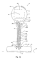
- FIG. 4B illustrates a cutaway front view of display device 10 and a positional interface 250 , showing select internal components to facilitate discussion, in accordance with another embodiment of the present invention.
- Interface 250 comprises a ball 252 and socket 254 combination that permits relative rotational movement between projection chamber 14 and base 12 .
- Ball 252 includes a ball portion 252 a and a coupling portion 252 b .
- Coupling portion 252 b is a rigid member fixed to base 12 on one end and to ball 252 a on the other end. Coupling portion 252 b provides clearance for projection chamber 14 so projection chamber 14 does not collide with base 12 .
- coupling portion 252 b attaches to housing 20 of base 12 proximate a center of mass 23 for base 12 .
- Socket 254 attaches to projection chamber 14 and couples to housing 32 of projection chamber 14 at receiving interface 29 .
- socket 254 attaches to housing 32 proximate to a center of mass 25 for projection chamber 14 .
- Socket 254 includes an inner receiving surface that matches outer surface dimensions of ball 252 . Dimensioning between the two surfaces is such that ball 252 and socket 254 a) allow rotational movement between the two surfaces and allow a user to position projection chamber 14 when a threshold force or greater is applied to the ball and socket, and b) provide sufficient resistance between the two surfaces to hold projection chamber 14 at a desired position. Thus, when the threshold force is not applied, ball 252 and socket 254 maintain a constant position between projection chamber 14 and base 12 . In operation, a user typically operates the two-degree of freedom joint by manually moving projection chamber 14 while holding base 12 .
- the threshold force for ball 252 and socket 254 is greater than a maximum force transmitted onto ball 252 and socket 254 by the weight of projection chamber 14 for any position of the projection chamber. This allows positional interface 250 to hold projection chamber 14 during usage without movement of the projected image.
- the threshold force may be increased by a buffer factor to achieve robust support of projection chamber 14 without drift; or to achieve a desired resistance for user interaction.
- Ball 252 and socket 254 also comprises an inner channel 256 .
- Channel 256 extends inside ball 252 and socket 254 from socket 254 , through the top of ball portion 252 a , to the bottom of coupling portion 252 b , and into base 12 .
- Channel 256 is suitably sized to receive fiber-optic cable 258 , electrical connectors 259 , and air duct 260 .
- Fiber optic cable 258 passes through channel 256 and has a first end 258 a in base 12 and a second end 258 b in projection chamber 14 .
- Electrical connectors 259 pass through channel 256 and provide electrical and digital communication between components within projection chamber 14 and components within base 12 .
- socket 254 is disposed as a portion of receiving interface 29 and housing 32 of projection chamber 14 . In this case, coupling of a top end of fiber-optic cable 258 to relay optics occurs within socket 254 /receiving interface 29 .
- the press fit and dimensioning of sleeve 282 and axle 284 is such that a user may move arm 272 relative to base 12 when a threshold force or greater is applied by the user to arm 272 .
- the press fit provides sufficient resistance between the sleeve 282 and axle 284 surfaces to hold projection chamber 14 at a desired position when the threshold force is not applied.
- the threshold force for sleeve 282 and axle 284 is greater than a maximum force transmitted onto joint 274 by the weight of projection chamber 14 for any position of the projection chamber. This allows positional interface 270 to hold a position of projection chamber 14 during usage without movement of the projected image.
- joint 274 uses an adjustable screw 284 that allows a user to change a holding force provided by joint 274 between arm 272 and base 12 ( FIG. 4D ). Turning screw 284 clockwise tightens joint 274 and increases the holding force on arm 272 , while turning screw 284 counterclockwise loosens joint 274 and decreases the holding force. In one embodiment, the holding force provided by screw 284 is proportional to the rotational position of screw 284 .
- positional interface 270 also includes a wrist joint 290 that permits rotation of projection chamber 14 and arm 272 about axis that passes through arm 272 .
- Arrow 273 illustrates the rotation provided by joint 290 , which allows rotation and positioning of joint 276 and projection chamber 14 about arm 272 ( FIG. 4C ).
- Joint 290 comprises an outer screw that allows user to manually tighten joint 290 for holding a desired position and loosen joint 290 for acquiring a desired position.
- wrist hinge 290 is disposed at the second end 272 b of arm 272 .
- Joint 290 may also be placed elsewhere along arm 272 , such as the midpoint of arm 272 or first end 272 a.
- positional interface 270 is illustrated with three joints 274 , 276 and 290 , two joints are also possible.
- joint 290 may be omitted from the design, leaving joints 274 and 276 as the two operational joints to move and position projection chamber 14 .
- positional interface 270 is disposed on a top wall or surface of base 12 and joint 274 is not used, while joint 290 is disposed at the top wall or surface.
- joint 290 permits rotation of arm 272 relative to the base 12 about a vertical axis perpendicular to the top surface
- joint 276 permits rotation of projection chamber 14 relative to arm 274 about an axis perpendicular to arm 272 .
- This design is suitable for use with a computer system where a computer tower or similar structure acts as base 12 .
- the computer system comprises computer system components within base 12 ; and positional interface 270 is then arranged on an upper portion of the computer tower.
- joint 274 includes a 135 degree range of motion 291 defined by mechanical stops included within joint 274 .
- arm 272 is parallel to a bottom surface of base 12 ( FIG. 4E ).
- arm 272 allows positioning of projection chamber above base 12 .
- joint 276 includes a 180 degree range of motion 293 , as shown in FIG. 4D . The first 135 degrees allow protection chamber 14 to travel from upward pointing angle 293 a to an angle 293 b that is parallel to arm 272 .
- the three joint positional interface 270 thus cooperate to provide a) a first position for projection chamber 14 that is above base 12 when base 12 rests on a flat surface, and b) a second position for projection chamber 14 that is beside base 12 when the base rests on the flat surface.
- display device 10 may be designed, and internal components within base 12 arranged, such that the center of mass 295 display device 10 is within a stability space provided by high friction pads 18 included in the bottom of base 12 .
- positional interface 270 comprises an air duct 296 , electrical connectors 297 and fiber optic cable 298 that pass from base 12 , through joint 274 , through arm 272 , through joint 276 , and into projection chamber 14 .
- slack is given to duct 296 , connectors 297 and cable 298 to permit the motion between projection chamber 14 and base 12 .
- duct 296 and connectors 297 are spiraled similar to a telephone wire used between a headset and base to permit the motion between projection chamber 14 and base 12 .
- FIG. 5A illustrates a process flow 300 for projecting video output from a display device in accordance with one embodiment of the invention.
- Video output from a display device described herein comprises light modulated according to video data included in a video signal.
- the video output may include a single image repeatedly displayed at the projector refresh rate over time, or for motion picture video output, a continuous sequence of images individually modulated by the optical modulation device.
- Light propagating through prism component 110 a reflects off a surface 110 d at interface 110 c by total internal reflection and forms a reflected pre-modulated beam directed towards optical modulation device 102 .
- the reflected pre-modulated beam travels through prism component 110 a to reach optical modulation device 102 .
- Each mirror in optical modulation device 102 reflects light in its ‘on’ state back into prism component 110 a and through interface 110 c without internal reflection such that the light propagates into prism component 110 b and out an exit face 110 e of prism 110 .
- Light output through exit face 110 e is characterized by output optical path 31 , which propagates through one or more projection lenses 112 that manipulate image light for enlarged display onto a screen or suitable receiving surface.
- An optical path output from the projection lens relates the location of a projected video output to the current projection lens direction and projection chamber position.
- the optical path characterizes a principal direction of light output from the projection lens.
- the present invention allows a user to change the location of light output on a receiving surface, such as a wall, for a projector by pointing the projection lens in one or more desired directions. For example, a user may point a projection lens and locate a projected image onto a wall between various obstacles on the wall by manipulating the position of the projection chamber.
- process flow 300 continues by receiving user input for a second projection lens direction ( 306 ) and projecting the video output towards a second receiving surface location ( 308 ).
- this occurs in response to a user manually pointing a projection lens included in the display device in a second direction directed at the second location, e.g., to avoid a new obstacle in the projection path, or to use a new receiving surface to facilitate viewing by new people.
- re-pointing of a projection lens and location of projected video output occurs without a user changing positioning between an object that supports the display device and a portion of the display device that includes the light source that generates light.
- base 12 includes the light source and is not moved between re-positioning of the projected video output.
- a spring-based clip attachment may be secured to base 12 (as described above with respect to FIG. 1 ) and clipped to a vertical wall such as that associated with a cubicle or bookshelf.
- the projection lens may be pointed and re-pointed without changing positioning between the base and the object that supports the base, namely, the vertical wall.
- a base including the light source rests on a table surface, shelf, one or more books, or another flat surface or object.
- the projection lens may be pointed and re-pointed without changing positioning between the base relative to the surface that the base rests upon.
- positional interface 200 of FIG. 4A allows a user to bend tubing 202 and orient projection chamber 14 and projection lens 37 to provide a horizontal image—regardless of the geometry between the object that supports base 12 and a horizontal image.
- tubing 202 may be bent 90 degrees to re-orient projection chamber 14 vertically and allow its projected video output for regular horizontal viewing.
- the first direction and the second direction differ by an angle of at least 30 degrees, such as that allowed by any the device designs described above.
- the angular difference may be in a lateral direction, a vertical direction, or some combination thereof.
- process flow 300 may also comprise horizontal keystone correcting the projected image. This typically occurs in response to user input via a keystone correction tool included with the projector, or implemented in software on a computer system that outputs video data to the projector.
- process flow 300 may also comprise vertical keystone correcting the projected image after vertical image location and direction changes of the projection lens relative to the base.
- first direction and the second direction differ by an angle of at least 60 degrees, as potentially allowed by one of the positional interfaces described above.
- Positional interface 200 of FIG. 4A may also permit the first direction and the second direction to differ by at least 90 degrees—vertically and/or laterally.
- Positional interface 270 is shown with a 180 degree change orientation between FIG. 4C and FIG. 4F , for example.
- FIG. 5B illustrates a process flow 320 for projecting video output from a display device in accordance with another embodiment of the invention.
- the display device used in process flow 320 permits pointing of a projection lens onto a surface that the display device rests upon.
- positional interface 200 that is long enough relative to a minimum throw distance for the projection lens system such that a user may point the projection lens towards a surface that the display device rests upon, thereby casting an image on the surface.
- the positional interface 200 is longer than the minimum throw distance.
- the corrugated tubing 202 may have a length between about 12 inches and about 24 inches.
- the projection lenses in display device 10 are designed to have a minimum throw distance from about 12 inches to about 18 inches, or less, for example.
- Light is then generated within the display device using a light source ( 324 ).
- One or more images are then formed by selectively transmitting light generated by the light source according to video data included in a video signal provided to an optical modulation device included in the display device.
- Light generation ( 324 ) and image formation ( 326 ) suitable for process flow 320 is described above in process flow 300 .
- the video output is projected onto the surface ( 328 ).
- the image is projected onto a different portion of the same surface that the projector rests upon, such as a portion forward from the display device when it rests on a table surface.
- the display device is designed for short range use and includes a projection lens system that aggressively enlarges the image as distance from the projection lens increases and as the image is projects from the display device.
- Process flow 320 may also comprise vertical keystone correcting the projected image in response to user input via a keystone correction tool included with the projector.
- the present invention divides projection display devices into multiple chambers.
- a chamber refers to a compartmented space dedicated to one or more functions of display device design.
- Display device 10 of FIG. 1 includes two main chambers: a light source chamber 65 within base 12 for generating and manipulating light for transmission to an optical modulation device; and projection chamber 14 for a) housing and servicing an optical modulation device that selectively transmits light according to image data and b) housing a projection lens system that outputs a projected image.
- Display device 10 also separates the two chambers with a degree of freedom provided by positional interface 16 .
- Multiple chamber configurations of the present invention separate a projector into multiple compartments and may improve projector design and performance.
- the multiple chamber design of display device 10 facilitates heat control.
- a light source and power supply contribute the largest share of heat production for a projector.
- the optical modulation device requires the strictest heat regulation requirements.
- the present invention places a light source and power supply into a chamber separate from a chamber that contains a heat sensitive optical modulation device.
- the multiple chamber design advantageously keeps heat sensitive components away from the heat generating components, thereby easing temperature control of the heat sensitive components.
- the multiple compartment design also facilitates control of heat conduction through a projector.
- heat conduction may be limited and channeled by design between multiple compartments to specific paths, e.g., through positional interface 16 for heat generated in housing 20 of base 12 that travels by conduction to housing 32 (and components therein) of projection chamber 14 . Heat conduction is then more readily controlled due to the limited and known paths of heat conduction.
- one or more rubber seals that reduce heat conduction may be placed at the coupling between positional interface 16 and housing 20 of base 12 or between positional interface 16 and housing 29 of projection chamber 20 .
- conventional rectangular static housing projector designs often conform in size to maximum dimensions of large hardware used to create and manage the light.
- cinder block projector designs are often regulated in a length or width by dimensions of the projection lens system and regulated in height by a lamp. This often creates considerable unused space within the rectangular projector, which increases size and encumbrance—and decreases portability—of the projector.
- the present invention however enables designers to customize chamber packaging according to component dimensions in each chamber, thereby conforming packaging to components within a chamber and minimizing unused space. This, for example, may allow projection chamber 14 to maintain a substantially cylindrical profile that matches the projection lens system; and may allow base 12 to occupy a smaller footprint than traditionally allowed by the output projection lens system.
- Display device 10 may employ design alternatives that reduce device weight. In one embodiment, display device 10 is less than five pounds. As mentioned above, walls of housing 32 and housing 20 may comprise a lightweight and stiff molded plastic or aluminum that reduces overall weight of display device 10 . In addition, embodiments including diode lasers for generating light reduce the weight of display device 10 relative to designs that employ a white light lamp and their associated light manipulation components, such as a color wheel, relay optics, color wheel motor, etc. In another embodiment, display device 10 is less than 2.5 pounds.
- set-top boxes associated with cable television services are becoming much more sophisticated user interfaces as interactive services become available to cable customers. Any of these devices may employ and benefit from video output using a display device as claimed herein.
- the scope of digital computer systems is expanding hurriedly and creating many systems and devices that may employ the present invention.
- a merging of television, video, and computer functions into a single device also adds value to the present invention since the sensitivity to image quality and size is high in applications such as motion picture viewing.
- Video game consoles that use large display devices may also benefit from the present invention.
- those skilled in the art will appreciate that the invention may be practiced with other computer system configurations, multiprocessor systems, microprocessor-based or programmable consumer electronics, minicomputers, mainframe computers, and the like.
- One software technique employs a more aggressive conservation power scheme when the display device operates on battery power and is not in use.
- Exemplary operation states include laptop use and PDA use.
- Exemplary graphics components include those that output video information for a word processing program, an Internet Browser interface, a graphics control, a music player program, and a video game.
- Display device 10 is well-suited for display of motion pictures and still photographs onto screens. In addition, display device 10 is also useful for conducting sales demonstrations, playing video games, general computer usage, business meetings, and classroom instruction, for example.
- Portable display devices of the present invention may provide projected images having an image size ranging from inches to many feet, as determined by a user and environment.
- Image size for a projector typically depends on mechanical factors such as the distance from the projector to the receiving surface and a splay angle for the projection lens. Since many conventional projectors and projectors of the present invention may offer image sizes with diagonal spans up to 30 feet, it is common for light output by a projector to encounter physical obstacles—either along a projection path between the projection lens and receiving surface, at the receiving surface, or both. Obstacles at the receiving surface often force a user to move a conventional cinder block projector closer to the wall to reduce image size.
- any obstacles along the one-dimensional light path between the projector and receiving surface also conventionally forced a user to move the cinder block projector.
- cinder block designs only offer one-dimensional output for a video image along an optical output path, which is fixed relative to the projector's base.
- moving the projector may not always be simple or feasible.
- the one-dimensional link often limits image placement and compromises usage.
- the present invention enables a user to flexibly locate a projected image in many positions relative to a single position of the display device.
- positioning between a projected image and a projector may vary three-dimensionally according to two dimensions of image placement offered by display devices described above, and a third dimension based on distance between the projector and receiving surface.
- This enables a user to avoid obstacles between a projector and a receiving surface, and to maximize image size based on specific conditions.
- a user may tailor projector output used in a living room or office to navigate projection path obstacles such as plants, bookshelves, etc., that normally would obstruct the projection path and limit where the projector is placed, where the receiving image is cast, and limit image size.
- the present invention also enables new uses for projectors.
- Cubicles and other portable office environments offer limited space, and often only a single suitable receiving surface. These confined environments also offer limited landing locations to rest a large footprint cinder block projector.
- Conventional cinder block projectors are currently not used in these environments due to the limited receiving surface space and the large number of obstacles that would be encountered between the receiving surface and the cinder block projector in its select few permissible landing locations.
- the present invention however enables a worker within confined spaces to a) locate the display device in many more locations due to its smaller footprint, b) readily clip the display device onto vertical walls with a clip attachment as described above with respect to FIG.
- positional interface 16 is relatively long and allows projection chamber 14 to be pointed down onto a surface that base 12 rests upon, such as a table. This allows display device 10 to be used in environments such as libraries, office desks and coffee shops where a user has table space but not wall space.
- display device is configured to increase display device endurance when relying on limited battery power reserves.
- the device may then be configured to reduce power consumption within a projection type display device using one or more hardware or software options.
- an array of diode lasers or non-lasing diodes generates light for subsequent optical modulation according to image data.
- diode lasers offer a light generation option that consumes significantly less power for a given image luminance.
- power consumption by fans employed for heat management within the display device is decreased since the diode array generates significantly less heat than a lamp.
- the diode array also outputs colored light, thereby eliminating the need for a color wheel and a motor that rotates the color wheel. This eliminates the power required for the color wheel motor. In addition, this reduces the power required for managing heat produced by the color wheel motor.
- the display device does not include audio output, which decreases size and reduces power consumption for the device.
Landscapes
- Physics & Mathematics (AREA)
- General Physics & Mathematics (AREA)
- Engineering & Computer Science (AREA)
- Multimedia (AREA)
- Signal Processing (AREA)
- Projection Apparatus (AREA)
- Transforming Electric Information Into Light Information (AREA)
Abstract
Description
Claims (24)
Priority Applications (1)
| Application Number | Priority Date | Filing Date | Title |
|---|---|---|---|
| US11/741,499 US7806535B2 (en) | 2003-07-16 | 2007-04-27 | Low power projection display devices |
Applications Claiming Priority (7)
| Application Number | Priority Date | Filing Date | Title |
|---|---|---|---|
| US48774403P | 2003-07-16 | 2003-07-16 | |
| US48769103P | 2003-07-16 | 2003-07-16 | |
| US48784903P | 2003-07-16 | 2003-07-16 | |
| US48786803P | 2003-07-16 | 2003-07-16 | |
| US48787103P | 2003-07-16 | 2003-07-16 | |
| US10/891,840 US7281807B2 (en) | 2003-07-16 | 2004-07-15 | Positionable projection display devices |
| US11/741,499 US7806535B2 (en) | 2003-07-16 | 2007-04-27 | Low power projection display devices |
Related Parent Applications (1)
| Application Number | Title | Priority Date | Filing Date |
|---|---|---|---|
| US10/891,840 Continuation US7281807B2 (en) | 2003-07-16 | 2004-07-15 | Positionable projection display devices |
Publications (2)
| Publication Number | Publication Date |
|---|---|
| US20070285344A1 US20070285344A1 (en) | 2007-12-13 |
| US7806535B2 true US7806535B2 (en) | 2010-10-05 |
Family
ID=34280231
Family Applications (8)
| Application Number | Title | Priority Date | Filing Date |
|---|---|---|---|
| US10/891,840 Expired - Fee Related US7281807B2 (en) | 2003-07-16 | 2004-07-15 | Positionable projection display devices |
| US11/741,585 Expired - Fee Related US7703930B2 (en) | 2003-07-16 | 2007-04-27 | Positioning interfaces for projection display devices |
| US11/741,150 Expired - Lifetime US7510284B2 (en) | 2003-07-16 | 2007-04-27 | Projection-type display devices including redundant laser sets |
| US11/741,217 Abandoned US20070195276A1 (en) | 2003-07-16 | 2007-04-27 | Projection-type display devices with reduced speckle |
| US11/741,499 Active 2026-09-03 US7806535B2 (en) | 2003-07-16 | 2007-04-27 | Low power projection display devices |
| US12/726,772 Expired - Lifetime US8147074B2 (en) | 2003-07-16 | 2010-03-18 | Positioning interfaces for projection display devices |
| US13/405,834 Expired - Fee Related US8366282B2 (en) | 2003-07-16 | 2012-02-27 | Positioning interfaces for projection display devices |
| US13/726,995 Expired - Fee Related US8641209B2 (en) | 2003-07-16 | 2012-12-26 | Positioning interfaces for projection display devices |
Family Applications Before (4)
| Application Number | Title | Priority Date | Filing Date |
|---|---|---|---|
| US10/891,840 Expired - Fee Related US7281807B2 (en) | 2003-07-16 | 2004-07-15 | Positionable projection display devices |
| US11/741,585 Expired - Fee Related US7703930B2 (en) | 2003-07-16 | 2007-04-27 | Positioning interfaces for projection display devices |
| US11/741,150 Expired - Lifetime US7510284B2 (en) | 2003-07-16 | 2007-04-27 | Projection-type display devices including redundant laser sets |
| US11/741,217 Abandoned US20070195276A1 (en) | 2003-07-16 | 2007-04-27 | Projection-type display devices with reduced speckle |
Family Applications After (3)
| Application Number | Title | Priority Date | Filing Date |
|---|---|---|---|
| US12/726,772 Expired - Lifetime US8147074B2 (en) | 2003-07-16 | 2010-03-18 | Positioning interfaces for projection display devices |
| US13/405,834 Expired - Fee Related US8366282B2 (en) | 2003-07-16 | 2012-02-27 | Positioning interfaces for projection display devices |
| US13/726,995 Expired - Fee Related US8641209B2 (en) | 2003-07-16 | 2012-12-26 | Positioning interfaces for projection display devices |
Country Status (1)
| Country | Link |
|---|---|
| US (8) | US7281807B2 (en) |
Cited By (4)
| Publication number | Priority date | Publication date | Assignee | Title |
|---|---|---|---|---|
| US20100245774A1 (en) * | 2009-03-27 | 2010-09-30 | Sanyo Electric Co., Ltd. | Projection display apparatus |
| US20120236212A1 (en) * | 2010-10-19 | 2012-09-20 | Tatsuo Itoh | Optical multiplexing apparatus and projector |
| US8641209B2 (en) * | 2003-07-16 | 2014-02-04 | Transpacific Image, Llc | Positioning interfaces for projection display devices |
| US20140146296A1 (en) * | 2012-11-23 | 2014-05-29 | Hon Hai Precision Industry Co., Ltd. | Projector |
Families Citing this family (85)
| Publication number | Priority date | Publication date | Assignee | Title |
|---|---|---|---|---|
| US7500758B1 (en) * | 2004-03-04 | 2009-03-10 | Sanyo Electric Co., Ltd. | Cameras and video players having image projection capabilities |
| US20060033676A1 (en) * | 2004-08-10 | 2006-02-16 | Kenneth Faase | Display device |
| WO2006068363A1 (en) * | 2004-12-21 | 2006-06-29 | Lg Electronics Inc. | Thin type projector |
| US7461941B2 (en) * | 2005-01-03 | 2008-12-09 | Monster Cable Products, Inc. | Uninterrupted power supply for projection lamp protection |
| JP4293163B2 (en) * | 2005-01-06 | 2009-07-08 | セイコーエプソン株式会社 | projector |
| US7539513B2 (en) * | 2005-02-02 | 2009-05-26 | National Telephone Products, Inc. | Portable phone with ergonomic image projection system |
| TWI262352B (en) * | 2005-03-10 | 2006-09-21 | Asustek Comp Inc | Luminant device |
| JPWO2006100857A1 (en) * | 2005-03-18 | 2008-08-28 | ハリソン東芝ライティング株式会社 | Lighting device |
| KR100620971B1 (en) * | 2005-03-30 | 2006-09-15 | 삼성전자주식회사 | Projection TV |
| US7429983B2 (en) * | 2005-11-01 | 2008-09-30 | Cheetah Omni, Llc | Packet-based digital display system |
| US8223213B2 (en) * | 2005-12-07 | 2012-07-17 | Wireless Avionics | Wireless and CCTV megapixel digital camera for surveillance and unmanned air vehicles |
| US8465183B2 (en) * | 2005-12-14 | 2013-06-18 | Koninklijke Philips Electronics N.V. | Lighting device and method for manufacturing same |
| USD565081S1 (en) | 2005-12-26 | 2008-03-25 | Seiko Epson Corporation | Projector |
| USD554685S1 (en) * | 2005-12-26 | 2007-11-06 | Seiko Epson Corporation | Projector |
| US7513627B2 (en) * | 2005-12-30 | 2009-04-07 | Honeywell International Inc. | Image projection system with vibration compensation |
| US7641348B2 (en) * | 2006-01-31 | 2010-01-05 | Hewlett-Packard Development Company, L.P. | Integrated portable computer projector system |
| TWM307806U (en) * | 2006-08-09 | 2007-03-11 | Chuan-Chao Tseng | Multi-media projector |
| US8132920B2 (en) | 2007-03-19 | 2012-03-13 | Motorola Mobility, Inc. | Thin microprojector with switched beam bender and method of operating the same |
| AU2008201153C1 (en) * | 2007-03-28 | 2011-01-06 | Aristocrat Technologies Australia Pty Limited | A Modular Visual Output Component |
| GB0707093D0 (en) * | 2007-04-12 | 2007-05-23 | Blue Sky Designs Ltd | Projector device |
| US7857460B2 (en) * | 2007-09-26 | 2010-12-28 | Motorola Mobility, Inc. | Image stabilization in a laser-scanning based projector |
| AU2008252054A1 (en) | 2007-12-18 | 2009-07-02 | Aristocrat Technologies Australia Pty Limited | A gaming machine and a network of gaming machines |
| WO2009078026A2 (en) * | 2007-12-19 | 2009-06-25 | Explay Ltd. | Portable projector |
| JP5294670B2 (en) * | 2008-03-27 | 2013-09-18 | 三洋電機株式会社 | Projection-type image display device and projection-type image display system using the same |
| US20090247283A1 (en) * | 2008-04-01 | 2009-10-01 | Chin-Jung Hou | Playing Table That Displays Scores To Users Clearly |
| TW200947101A (en) * | 2008-05-12 | 2009-11-16 | Coretronic Corp | Projector and maintenance system for ballast thereof |
| WO2009142503A1 (en) * | 2008-05-19 | 2009-11-26 | Global Control Center Design As | Device and system for projecting images onto a screen |
| JP2010014815A (en) * | 2008-07-01 | 2010-01-21 | Mitsubishi Electric Corp | Projection type display device |
| JP5106309B2 (en) * | 2008-08-07 | 2012-12-26 | 三菱電機株式会社 | Projection display |
| US20100253769A1 (en) * | 2008-09-04 | 2010-10-07 | Laser Light Engines | Optical System and Assembly Method |
| US20100103332A1 (en) * | 2008-10-27 | 2010-04-29 | Motorola, Inc. | Image projector driving multiple display screens |
| CN102224456A (en) * | 2008-11-26 | 2011-10-19 | 三洋电机株式会社 | Illuminating device and projection image display device |
| NL1036496C2 (en) * | 2009-02-02 | 2010-08-03 | Vogel S Holding Bv | DEVICE FOR SPACIOUS POSITIONING OF VISUAL EQUIPMENT AT A PARTICULAR POSITION. |
| WO2010125978A1 (en) * | 2009-04-30 | 2010-11-04 | 三菱電機株式会社 | Laser illumination device, illumination method, semiconductor element fabrication method, projection-type display device, and image display method using projection-type display device |
| US20100309391A1 (en) * | 2009-06-03 | 2010-12-09 | Honeywood Technologies, Llc | Multi-source projection-type display |
| GB2470783A (en) * | 2009-06-05 | 2010-12-08 | Data Systems T | Portable image projector and projection method |
| US10678061B2 (en) | 2009-09-03 | 2020-06-09 | Laser Light Engines, Inc. | Low etendue illumination |
| JP4991834B2 (en) | 2009-12-17 | 2012-08-01 | シャープ株式会社 | Vehicle headlamp |
| JP5232815B2 (en) * | 2010-02-10 | 2013-07-10 | シャープ株式会社 | Vehicle headlamp |
| US9066412B2 (en) * | 2010-04-15 | 2015-06-23 | Asml Netherlands B.V. | Systems and methods for cooling an optic |
| JP5255018B2 (en) * | 2010-05-17 | 2013-08-07 | シャープ株式会社 | Laser downlight and laser downlight system |
| US8733996B2 (en) | 2010-05-17 | 2014-05-27 | Sharp Kabushiki Kaisha | Light emitting device, illuminating device, and vehicle headlamp |
| DE102010039683A1 (en) * | 2010-08-24 | 2012-03-01 | Osram Ag | Projection apparatus and method for operating a projection apparatus |
| US9816677B2 (en) | 2010-10-29 | 2017-11-14 | Sharp Kabushiki Kaisha | Light emitting device, vehicle headlamp, illumination device, and laser element |
| US9346395B2 (en) * | 2011-03-08 | 2016-05-24 | Sharp Kabushiki Kaisha | Light-emitting apparatus, illumination system, vehicle headlamp, projector, and method for manufacturing light-emitting apparatus |
| US8690358B2 (en) | 2011-06-27 | 2014-04-08 | Microsoft Corporation | Video projection device for mobile device having a first projection surface integral with a surface of the mobile device |
| US20130010266A1 (en) * | 2011-07-05 | 2013-01-10 | Projectiondesign As | Compact Projector Head |
| JP5664979B2 (en) | 2011-11-04 | 2015-02-04 | 株式会社リコー | Image projection device |
| US20130215402A1 (en) * | 2012-01-30 | 2013-08-22 | Rob Sugarman | Modular projector |
| TWI588560B (en) | 2012-04-05 | 2017-06-21 | 布萊恩荷登視覺協會 | Lens, device, method and system for refractive error |
| US9201250B2 (en) | 2012-10-17 | 2015-12-01 | Brien Holden Vision Institute | Lenses, devices, methods and systems for refractive error |
| HK1212194A1 (en) | 2012-10-17 | 2016-06-10 | Brien Holden Vision Institute | Lenses, devices, methods and systems for refractive error |
| TWI464521B (en) * | 2012-11-02 | 2014-12-11 | Hon Hai Prec Ind Co Ltd | Cooling apparatus of porjector |
| TWM457188U (en) * | 2012-11-16 | 2013-07-11 | Azurewave Technologies Inc | Projection device for increasing transmission efficiency of light |
| CN103838067A (en) * | 2012-11-26 | 2014-06-04 | 鸿富锦精密工业(深圳)有限公司 | Projector cooling device |
| CN103869586B (en) * | 2012-12-18 | 2017-02-08 | 中强光电股份有限公司 | Projection device |
| WO2014171147A1 (en) * | 2013-04-18 | 2014-10-23 | パナソニック株式会社 | Projection type image display device |
| JP2015094860A (en) * | 2013-11-12 | 2015-05-18 | 株式会社リコー | Illumination light source device and image projection device |
| KR101625473B1 (en) * | 2014-07-18 | 2016-05-30 | 삼성전자 주식회사 | Magnetic resonance imaging apparatus |
| JP2016062272A (en) * | 2014-09-17 | 2016-04-25 | 株式会社リコー | Transmission system, transmission management system, transmission method, and program |
| TWI556017B (en) * | 2014-10-16 | 2016-11-01 | 信泰光學(深圳)有限公司 | Pico projector |
| CN105842967B (en) * | 2015-01-12 | 2018-03-02 | 信泰光学(深圳)有限公司 | Micro- projector |
| JP6519188B2 (en) * | 2015-01-15 | 2019-05-29 | セイコーエプソン株式会社 | Light source device and projector |
| US10326252B2 (en) * | 2015-05-06 | 2019-06-18 | Microsoft Technology Licensing, Llc | Beam projection for fast axis expansion |
| US10474311B2 (en) * | 2015-05-28 | 2019-11-12 | Clemtek Llc | Gaming video processing system |
| USD790003S1 (en) * | 2015-08-25 | 2017-06-20 | Seiko Epson Corporation | Projector |
| KR20170039027A (en) * | 2015-09-30 | 2017-04-10 | 삼성디스플레이 주식회사 | Backlight unit and display apparatus including the same |
| US11148165B2 (en) * | 2016-02-17 | 2021-10-19 | Wet | Water on wall display |
| US10191358B2 (en) * | 2016-04-13 | 2019-01-29 | Angela Jorgensen | Moving head projector system |
| US10491868B2 (en) * | 2016-08-05 | 2019-11-26 | Maxell, Ltd. | Projection video display apparatus |
| US9778478B1 (en) | 2016-10-04 | 2017-10-03 | Christine Digital Systems Usa, Inc. | Projector with image plane modal vibration for speckle reduction |
| CN110855963B (en) * | 2018-08-21 | 2022-03-08 | 视联动力信息技术股份有限公司 | Video data projection method and device |
| CN111308841A (en) | 2018-12-11 | 2020-06-19 | 深圳光峰科技股份有限公司 | Wavelength conversion device and light source system |
| USD880564S1 (en) * | 2018-12-13 | 2020-04-07 | Compal Electronics, Inc. | Projector equipped with a lamp |
| USD888132S1 (en) * | 2018-12-13 | 2020-06-23 | Compal Electronics, Inc. | Projector equipped with functional module |
| USD898105S1 (en) * | 2018-12-18 | 2020-10-06 | Seasonal Specialties, Llc | Projector |
| US10907794B2 (en) * | 2019-02-27 | 2021-02-02 | Magna Closures Inc. | Headlight assembly with lens heater |
| WO2021025002A1 (en) * | 2019-08-05 | 2021-02-11 | パナソニックIpマネジメント株式会社 | Light source device and projection-type display apparatus |
| CN111193914A (en) * | 2020-01-10 | 2020-05-22 | 厦门卓旭智能科技有限公司 | Projector convenient to calibration projection position and good stability |
| US20230224439A1 (en) * | 2020-04-24 | 2023-07-13 | Panasonic Intellectual Property Management Co., Ltd. | Projection system |
| CN113766097B (en) * | 2020-06-05 | 2025-01-03 | 中兴通讯股份有限公司 | Camera, camera control method, terminal, electronic device and storage medium |
| CN111775853A (en) * | 2020-07-22 | 2020-10-16 | 盐城工学院 | A car projector |
| USD952730S1 (en) * | 2020-08-13 | 2022-05-24 | Shenzhen Shadow Crown Technology Co., Ltd | Projector |
| CN113075843B (en) * | 2020-12-23 | 2022-12-27 | 深圳市安华光电技术有限公司 | Projection optical machine and projector |
| CN118409468A (en) * | 2023-01-30 | 2024-07-30 | 中强光电股份有限公司 | Projection device |
Citations (87)
| Publication number | Priority date | Publication date | Assignee | Title |
|---|---|---|---|---|
| US4969733A (en) | 1989-10-02 | 1990-11-13 | Dukane Corporation | Foldable portable overhead projector |
| US4978218A (en) | 1990-03-01 | 1990-12-18 | Minnesota Mining And Manufacturing Company | Folding arm for overhead projector |
| US5098184A (en) | 1989-04-28 | 1992-03-24 | U.S. Philips Corporation | Optical illumination system and projection apparatus comprising such a system |
| US5136675A (en) | 1990-12-20 | 1992-08-04 | General Electric Company | Slewable projection system with fiber-optic elements |
| US5170196A (en) | 1990-12-03 | 1992-12-08 | Sony Corporation | Portable projector |
| US5278596A (en) | 1992-05-19 | 1994-01-11 | Machtig Jeffrey S | LCD projection apparatus |
| US5287132A (en) | 1991-02-16 | 1994-02-15 | Fuji Photo Film Co., Ltd. | Video projector |
| US5343489A (en) | 1991-07-23 | 1994-08-30 | Carl-Zeiss-Stiftung | Arrangement for shaping a laser beam and for reducing the coherence thereof |
| US5347324A (en) | 1991-06-27 | 1994-09-13 | Fuji Photo Film Co., Ltd. | Video projector with battery and replaceable lamp unit |
| US5394254A (en) | 1991-11-01 | 1995-02-28 | Greyhawk Systems, Inc. | Light valve projector assembly including fiber optic plate with fiber bundle perimeter less than twice as reflective as elsewhere |
| US5416541A (en) | 1994-05-16 | 1995-05-16 | Fog; Stephen C. | Folding portable overhead projector |
| US5418583A (en) | 1992-03-31 | 1995-05-23 | Matsushita Electric Industrial Co., Ltd. | Optical illumination system and projection display apparatus using the same |
| US5515391A (en) | 1994-03-07 | 1996-05-07 | Sdl, Inc. | Thermally balanced diode laser package |
| US5534950A (en) | 1993-10-04 | 1996-07-09 | Laser Power Corporation | High resolution image projection system and method employing lasers |
| US5612968A (en) | 1995-04-20 | 1997-03-18 | Bell Communications Research, Inc. | Redundant multi-wavelength laser arrays |
| US5624173A (en) | 1996-03-19 | 1997-04-29 | Davidson; Steven | Video frame system |
| US5651599A (en) | 1991-02-22 | 1997-07-29 | Seiko Epson Corporation | Projection type liquid crystal projector |
| US5654776A (en) | 1994-10-14 | 1997-08-05 | Kabushiki Kaisha Toshiba | Multiscreen displaying apparatus |
| US5668595A (en) | 1992-03-23 | 1997-09-16 | Canon Kabushiki Kaisha | Multi-lens imaging apparatus having a mechanism for combining a plurality of images without displacement of registration |
| US5700076A (en) | 1994-07-25 | 1997-12-23 | Proxima Corporation | Laser illuminated image producing system and method of using same |
| US5782548A (en) | 1995-04-07 | 1998-07-21 | Seiko Epson Corporation | Image projection system and a method of controlling a projected pointer |
| US5818639A (en) | 1995-09-21 | 1998-10-06 | Kabushiki Kaisha Toshiba | Multiscreen displaying apparatus and screen fitting structure |
| US5851060A (en) | 1995-09-13 | 1998-12-22 | Nikon Corporation | Projective display device |
| US5927985A (en) | 1994-10-31 | 1999-07-27 | Mcdonnell Douglas Corporation | Modular video display system |
| US5959702A (en) | 1996-10-04 | 1999-09-28 | Goodman; John Mott | Lensless video projector |
| US5959778A (en) | 1997-01-31 | 1999-09-28 | Nikon Corporation | Projection-display apparatus |
| US5971545A (en) | 1997-06-25 | 1999-10-26 | Hewlett-Packard Company | Light source for projection display |
| US5990983A (en) | 1994-09-30 | 1999-11-23 | Laser Power Corporation | High resolution image projection system and method employing lasers |
| US6042068A (en) | 1997-09-04 | 2000-03-28 | Peerless Indsutries, Inc. | Low profile LCD projector mount |
| US6075504A (en) | 1993-03-19 | 2000-06-13 | Photonics Systems, Inc. | Flat panel display screens and systems |
| US6089717A (en) | 1996-09-02 | 2000-07-18 | Sony Corporation | Projector apparatus |
| US6137638A (en) | 1999-07-28 | 2000-10-24 | Nittoh Kogaku K.K. | Projection zoom lens system and projector apparatus |
| US6155687A (en) | 1999-07-16 | 2000-12-05 | Infocus Corporation | Light guide for use in a color wheel display synchronization apparatus and method |
| US6170953B1 (en) | 1999-03-22 | 2001-01-09 | Samsung Electronics Co., Ltd. | Laser video projector for projecting image to a plurality of screens |
| US6179426B1 (en) | 1999-03-03 | 2001-01-30 | 3M Innovative Properties Company | Integrated front projection system |
| US6183092B1 (en) | 1998-05-01 | 2001-02-06 | Diane Troyer | Laser projection apparatus with liquid-crystal light valves and scanning reading beam |
| US6185047B1 (en) | 1999-05-17 | 2001-02-06 | Infocus Corporation | Image projection system packaged to operate lying flat with a very low profile |
| US6191826B1 (en) | 1996-11-19 | 2001-02-20 | Sony Corporation | Projector apparatus |
| US6224216B1 (en) | 2000-02-18 | 2001-05-01 | Infocus Corporation | System and method employing LED light sources for a projection display |
| US6246446B1 (en) | 1996-06-28 | 2001-06-12 | Texas Instruments Incorporated | Auto focus system for a SLM based image display system |
| US6317170B1 (en) | 1997-09-13 | 2001-11-13 | Samsung Electronics Co., Ltd. | Large screen compact image projection apparatus using a hybrid video laser color mixer |
| US6323984B1 (en) | 2000-10-11 | 2001-11-27 | Silicon Light Machines | Method and apparatus for reducing laser speckle |
| US6350033B1 (en) | 1998-11-10 | 2002-02-26 | Seiko Epson Corporation | Projector |
| US6367935B1 (en) | 1997-01-31 | 2002-04-09 | Eads Deutschland Gmbh | Method and device for eliminating image speckles in scanning laser image projection |
| US6373646B1 (en) | 1998-11-06 | 2002-04-16 | Laserpromotions Beheer B.V. I.O. | Laser projection apparatus |
| US6392821B1 (en) | 2000-09-28 | 2002-05-21 | William R. Benner, Jr. | Light display projector with wide angle capability and associated method |
| US6394606B1 (en) | 1998-09-29 | 2002-05-28 | Sony Corporation | Projection-type display device |
| US6416184B1 (en) | 1999-02-25 | 2002-07-09 | Seiko Epson Corporation | Projector with dustproof ventilating member |
| US6426781B1 (en) | 1999-03-26 | 2002-07-30 | Samsung Electronics Co., Ltd. | Laser video projector |
| US6426836B2 (en) | 1996-06-11 | 2002-07-30 | Hewlett-Packard Co. | Method and apparatus for reducing the formation of spots in laser projection |
| US6435682B1 (en) | 1999-02-17 | 2002-08-20 | Victor Company Of Japan, Limited | Laser imaging using a spatial light modulator |
| US6445487B1 (en) | 2001-02-20 | 2002-09-03 | Eastman Kodak Company | Speckle suppressed laser projection system using a multi-wavelength doppler shifted beam |
| US20020126479A1 (en) | 2001-03-08 | 2002-09-12 | Ball Semiconductor, Inc. | High power incoherent light source with laser array |
| US6454417B1 (en) | 1999-03-05 | 2002-09-24 | Minolta Co., Ltd. | Projection optical system comprising an optical function surface for reflecting or transmitting light from a spatial light modulator |
| US6472828B1 (en) | 2000-06-23 | 2002-10-29 | Infocus Corporation | Control for projector lamp heat dissipation |
| US6480634B1 (en) | 2000-05-18 | 2002-11-12 | Silicon Light Machines | Image projector including optical fiber which couples laser illumination to light modulator |
| US6481855B2 (en) | 2001-01-12 | 2002-11-19 | Infocus Corporation | Keystone distortion correction system for use in multimedia projectors |
| US6481852B2 (en) | 2000-03-06 | 2002-11-19 | Nec Corporation | Projector apparatus comprising a light composing optical system vertically stacked with respect to a light separation optical system |
| US6488380B1 (en) | 1999-11-24 | 2002-12-03 | Seiko Epson Corporation | Projector having a light shielding member |
| US6490011B1 (en) | 1998-12-18 | 2002-12-03 | Caterpillar Inc | Display device convertible between a cave configuration and a wall configuration |
| US6491398B2 (en) | 1999-01-08 | 2002-12-10 | Nec Viewtechnology, Ltd. | Video projector |
| US6501866B2 (en) | 2000-02-25 | 2002-12-31 | Mahi Networks. Inc. | Method and apparatus for cross-connecting optical transmission signals |
| US6594090B2 (en) | 2001-08-27 | 2003-07-15 | Eastman Kodak Company | Laser projection display system |
| US6600590B2 (en) | 2001-02-20 | 2003-07-29 | Eastman Kodak Company | Speckle suppressed laser projection system using RF injection |
| US6604829B2 (en) | 1999-03-03 | 2003-08-12 | 3M Innovative Properties Company | Compact integrated front projection system |
| US6625381B2 (en) | 2001-02-20 | 2003-09-23 | Eastman Kodak Company | Speckle suppressed laser projection system with partial beam reflection |
| US6636339B2 (en) | 2000-11-03 | 2003-10-21 | Samsung Electronics Co., Ltd. | Optical scanner, laser image projector adopting the optical scanner, and method of driving the laser image projector |
| US6665478B1 (en) | 2000-10-13 | 2003-12-16 | Alcatel | Fiber optic cable with non-corrugated armor shielding |
| US6709114B1 (en) | 2000-01-27 | 2004-03-23 | Thomson Licensing S.A. | Spherical mounting system for three axis adjustment of light projector assembly in a projection television |
| US6728274B1 (en) | 2001-09-14 | 2004-04-27 | Multiwave Networks Portugal Lda | Multi-wavelength laser apparatus and method |
| US6736517B2 (en) | 2001-02-28 | 2004-05-18 | Principia Lightworks Inc. | Dual mode laser projection system for electronic and film images |
| US6747781B2 (en) | 2001-06-25 | 2004-06-08 | Silicon Light Machines, Inc. | Method, apparatus, and diffuser for reducing laser speckle |
| US20040135874A1 (en) | 2003-01-14 | 2004-07-15 | Eastman Kodak Company | Light source using large area LEDs |
| US6764107B1 (en) | 2002-05-08 | 2004-07-20 | Hassan Obahi | Self-sealing pre-assembled endfitting/coupling for corrugated tubing |
| US6769772B2 (en) | 2002-10-11 | 2004-08-03 | Eastman Kodak Company | Six color display apparatus having increased color gamut |
| US6771326B2 (en) | 2000-10-26 | 2004-08-03 | General Atomics, Inc. | Multi-screen laser projection system using a shared laser source |
| US6790205B1 (en) | 2000-03-01 | 2004-09-14 | Ya-Man Ltd. | Laser beam projector |
| US6801299B2 (en) | 2002-07-31 | 2004-10-05 | Asml Holding N.V. | System for laser beam expansion without expanding spatial coherence |
| US6807010B2 (en) | 2002-11-13 | 2004-10-19 | Eastman Kodak Company | Projection display apparatus having both incoherent and laser light sources |
| US6817632B1 (en) | 2002-09-13 | 2004-11-16 | Fleetguard, Inc. | Flex tube joint with torsion relief |
| US6821026B2 (en) | 2002-09-04 | 2004-11-23 | International Business Machines Corporation | Redundant configurable VCSEL laser array optical light source |
| US6864861B2 (en) | 1997-12-31 | 2005-03-08 | Brillian Corporation | Image generator having a miniature display device |
| US20050147135A1 (en) | 2002-11-25 | 2005-07-07 | Eastman Kodak Company | Multi-spectral laser array and optical system |
| US7088321B1 (en) | 2001-03-30 | 2006-08-08 | Infocus Corporation | Method and apparatus for driving LED light sources for a projection display |
| US7156522B2 (en) | 2003-07-16 | 2007-01-02 | Plut William J | Projection-type display devices with reduced weight and size |
| US20070145915A1 (en) | 2003-05-05 | 2007-06-28 | Color Kinetics Incorporated | Lighting methods and systems |
| US20070195276A1 (en) | 2003-07-16 | 2007-08-23 | Plut William J | Projection-type display devices with reduced speckle |
Family Cites Families (12)
| Publication number | Priority date | Publication date | Assignee | Title |
|---|---|---|---|---|
| CA939016A (en) * | 1972-02-02 | 1973-12-25 | Bell Canada-Northern Electric Research Limited | Active delay-equalizer network |
| DE3512465A1 (en) * | 1985-04-04 | 1986-10-09 | Demolux Gmbh & Co Kg, 6070 Langen | OVERHEAD PROJECTOR |
| JP2551854Y2 (en) * | 1990-05-24 | 1997-10-27 | 富士写真フイルム株式会社 | LCD projector |
| DE59306619D1 (en) | 1992-01-29 | 1997-07-10 | Thomson Brandt Gmbh | Video camera, optionally operable as a projector |
| JP3041582B2 (en) * | 1995-03-22 | 2000-05-15 | セイコーインスツルメンツ株式会社 | Linear image sensor IC |
| US6545654B2 (en) | 1996-10-31 | 2003-04-08 | Kopin Corporation | Microdisplay for portable communication systems |
| JP3585097B2 (en) | 1998-06-04 | 2004-11-04 | セイコーエプソン株式会社 | Light source device, optical device and liquid crystal display device |
| US20020063855A1 (en) | 2000-11-29 | 2002-05-30 | Williams John W. | Digital projection system for phones and personal digital assistants |
| US6806850B2 (en) * | 2001-02-23 | 2004-10-19 | Shane Chen | Portable electronic device having projection screen |
| US20020176015A1 (en) | 2001-05-23 | 2002-11-28 | Lichtfuss Hans A. | Image capturing camera and projector device |
| US6577429B1 (en) * | 2002-01-15 | 2003-06-10 | Eastman Kodak Company | Laser projection display system |
| JP2004156657A (en) * | 2002-11-05 | 2004-06-03 | Yamaha Motor Co Ltd | Engine drive belt cooling structure |
-
2004
- 2004-07-15 US US10/891,840 patent/US7281807B2/en not_active Expired - Fee Related
-
2007
- 2007-04-27 US US11/741,585 patent/US7703930B2/en not_active Expired - Fee Related
- 2007-04-27 US US11/741,150 patent/US7510284B2/en not_active Expired - Lifetime
- 2007-04-27 US US11/741,217 patent/US20070195276A1/en not_active Abandoned
- 2007-04-27 US US11/741,499 patent/US7806535B2/en active Active
-
2010
- 2010-03-18 US US12/726,772 patent/US8147074B2/en not_active Expired - Lifetime
-
2012
- 2012-02-27 US US13/405,834 patent/US8366282B2/en not_active Expired - Fee Related
- 2012-12-26 US US13/726,995 patent/US8641209B2/en not_active Expired - Fee Related
Patent Citations (93)
| Publication number | Priority date | Publication date | Assignee | Title |
|---|---|---|---|---|
| US5098184A (en) | 1989-04-28 | 1992-03-24 | U.S. Philips Corporation | Optical illumination system and projection apparatus comprising such a system |
| US4969733A (en) | 1989-10-02 | 1990-11-13 | Dukane Corporation | Foldable portable overhead projector |
| US4978218A (en) | 1990-03-01 | 1990-12-18 | Minnesota Mining And Manufacturing Company | Folding arm for overhead projector |
| US5170196A (en) | 1990-12-03 | 1992-12-08 | Sony Corporation | Portable projector |
| US5136675A (en) | 1990-12-20 | 1992-08-04 | General Electric Company | Slewable projection system with fiber-optic elements |
| US5287132A (en) | 1991-02-16 | 1994-02-15 | Fuji Photo Film Co., Ltd. | Video projector |
| US5651599A (en) | 1991-02-22 | 1997-07-29 | Seiko Epson Corporation | Projection type liquid crystal projector |
| US5347324A (en) | 1991-06-27 | 1994-09-13 | Fuji Photo Film Co., Ltd. | Video projector with battery and replaceable lamp unit |
| US5343489A (en) | 1991-07-23 | 1994-08-30 | Carl-Zeiss-Stiftung | Arrangement for shaping a laser beam and for reducing the coherence thereof |
| US5394254A (en) | 1991-11-01 | 1995-02-28 | Greyhawk Systems, Inc. | Light valve projector assembly including fiber optic plate with fiber bundle perimeter less than twice as reflective as elsewhere |
| US5668595A (en) | 1992-03-23 | 1997-09-16 | Canon Kabushiki Kaisha | Multi-lens imaging apparatus having a mechanism for combining a plurality of images without displacement of registration |
| US5418583A (en) | 1992-03-31 | 1995-05-23 | Matsushita Electric Industrial Co., Ltd. | Optical illumination system and projection display apparatus using the same |
| US5278596A (en) | 1992-05-19 | 1994-01-11 | Machtig Jeffrey S | LCD projection apparatus |
| US6075504A (en) | 1993-03-19 | 2000-06-13 | Photonics Systems, Inc. | Flat panel display screens and systems |
| US5534950A (en) | 1993-10-04 | 1996-07-09 | Laser Power Corporation | High resolution image projection system and method employing lasers |
| US5515391A (en) | 1994-03-07 | 1996-05-07 | Sdl, Inc. | Thermally balanced diode laser package |
| US5416541A (en) | 1994-05-16 | 1995-05-16 | Fog; Stephen C. | Folding portable overhead projector |
| US5700076A (en) | 1994-07-25 | 1997-12-23 | Proxima Corporation | Laser illuminated image producing system and method of using same |
| US5990983A (en) | 1994-09-30 | 1999-11-23 | Laser Power Corporation | High resolution image projection system and method employing lasers |
| US5654776A (en) | 1994-10-14 | 1997-08-05 | Kabushiki Kaisha Toshiba | Multiscreen displaying apparatus |
| US5927985A (en) | 1994-10-31 | 1999-07-27 | Mcdonnell Douglas Corporation | Modular video display system |
| US5782548A (en) | 1995-04-07 | 1998-07-21 | Seiko Epson Corporation | Image projection system and a method of controlling a projected pointer |
| US5612968A (en) | 1995-04-20 | 1997-03-18 | Bell Communications Research, Inc. | Redundant multi-wavelength laser arrays |
| US5851060A (en) | 1995-09-13 | 1998-12-22 | Nikon Corporation | Projective display device |
| US5818639A (en) | 1995-09-21 | 1998-10-06 | Kabushiki Kaisha Toshiba | Multiscreen displaying apparatus and screen fitting structure |
| US5624173A (en) | 1996-03-19 | 1997-04-29 | Davidson; Steven | Video frame system |
| US6426836B2 (en) | 1996-06-11 | 2002-07-30 | Hewlett-Packard Co. | Method and apparatus for reducing the formation of spots in laser projection |
| US6246446B1 (en) | 1996-06-28 | 2001-06-12 | Texas Instruments Incorporated | Auto focus system for a SLM based image display system |
| US6089717A (en) | 1996-09-02 | 2000-07-18 | Sony Corporation | Projector apparatus |
| US5959702A (en) | 1996-10-04 | 1999-09-28 | Goodman; John Mott | Lensless video projector |
| US6191826B1 (en) | 1996-11-19 | 2001-02-20 | Sony Corporation | Projector apparatus |
| US6367935B1 (en) | 1997-01-31 | 2002-04-09 | Eads Deutschland Gmbh | Method and device for eliminating image speckles in scanning laser image projection |
| US5959778A (en) | 1997-01-31 | 1999-09-28 | Nikon Corporation | Projection-display apparatus |
| US5971545A (en) | 1997-06-25 | 1999-10-26 | Hewlett-Packard Company | Light source for projection display |
| US6042068A (en) | 1997-09-04 | 2000-03-28 | Peerless Indsutries, Inc. | Low profile LCD projector mount |
| US6317170B1 (en) | 1997-09-13 | 2001-11-13 | Samsung Electronics Co., Ltd. | Large screen compact image projection apparatus using a hybrid video laser color mixer |
| US6864861B2 (en) | 1997-12-31 | 2005-03-08 | Brillian Corporation | Image generator having a miniature display device |
| US6183092B1 (en) | 1998-05-01 | 2001-02-06 | Diane Troyer | Laser projection apparatus with liquid-crystal light valves and scanning reading beam |
| US6394606B1 (en) | 1998-09-29 | 2002-05-28 | Sony Corporation | Projection-type display device |
| US6373646B1 (en) | 1998-11-06 | 2002-04-16 | Laserpromotions Beheer B.V. I.O. | Laser projection apparatus |
| US6350033B1 (en) | 1998-11-10 | 2002-02-26 | Seiko Epson Corporation | Projector |
| US6490011B1 (en) | 1998-12-18 | 2002-12-03 | Caterpillar Inc | Display device convertible between a cave configuration and a wall configuration |
| US6491398B2 (en) | 1999-01-08 | 2002-12-10 | Nec Viewtechnology, Ltd. | Video projector |
| US6435682B1 (en) | 1999-02-17 | 2002-08-20 | Victor Company Of Japan, Limited | Laser imaging using a spatial light modulator |
| US6416184B1 (en) | 1999-02-25 | 2002-07-09 | Seiko Epson Corporation | Projector with dustproof ventilating member |
| US6179426B1 (en) | 1999-03-03 | 2001-01-30 | 3M Innovative Properties Company | Integrated front projection system |
| US6604829B2 (en) | 1999-03-03 | 2003-08-12 | 3M Innovative Properties Company | Compact integrated front projection system |
| US6454417B1 (en) | 1999-03-05 | 2002-09-24 | Minolta Co., Ltd. | Projection optical system comprising an optical function surface for reflecting or transmitting light from a spatial light modulator |
| US6170953B1 (en) | 1999-03-22 | 2001-01-09 | Samsung Electronics Co., Ltd. | Laser video projector for projecting image to a plurality of screens |
| US6426781B1 (en) | 1999-03-26 | 2002-07-30 | Samsung Electronics Co., Ltd. | Laser video projector |
| US6185047B1 (en) | 1999-05-17 | 2001-02-06 | Infocus Corporation | Image projection system packaged to operate lying flat with a very low profile |
| US6471356B1 (en) | 1999-05-17 | 2002-10-29 | Infocus Corporation | Portable image projection system having reduced weight and profile |
| US6155687A (en) | 1999-07-16 | 2000-12-05 | Infocus Corporation | Light guide for use in a color wheel display synchronization apparatus and method |
| US6137638A (en) | 1999-07-28 | 2000-10-24 | Nittoh Kogaku K.K. | Projection zoom lens system and projector apparatus |
| US6488380B1 (en) | 1999-11-24 | 2002-12-03 | Seiko Epson Corporation | Projector having a light shielding member |
| US6709114B1 (en) | 2000-01-27 | 2004-03-23 | Thomson Licensing S.A. | Spherical mounting system for three axis adjustment of light projector assembly in a projection television |
| US6224216B1 (en) | 2000-02-18 | 2001-05-01 | Infocus Corporation | System and method employing LED light sources for a projection display |
| US6501866B2 (en) | 2000-02-25 | 2002-12-31 | Mahi Networks. Inc. | Method and apparatus for cross-connecting optical transmission signals |
| US6790205B1 (en) | 2000-03-01 | 2004-09-14 | Ya-Man Ltd. | Laser beam projector |
| US6481852B2 (en) | 2000-03-06 | 2002-11-19 | Nec Corporation | Projector apparatus comprising a light composing optical system vertically stacked with respect to a light separation optical system |
| US6480634B1 (en) | 2000-05-18 | 2002-11-12 | Silicon Light Machines | Image projector including optical fiber which couples laser illumination to light modulator |
| US6472828B1 (en) | 2000-06-23 | 2002-10-29 | Infocus Corporation | Control for projector lamp heat dissipation |
| US6392821B1 (en) | 2000-09-28 | 2002-05-21 | William R. Benner, Jr. | Light display projector with wide angle capability and associated method |
| US6323984B1 (en) | 2000-10-11 | 2001-11-27 | Silicon Light Machines | Method and apparatus for reducing laser speckle |
| US6665478B1 (en) | 2000-10-13 | 2003-12-16 | Alcatel | Fiber optic cable with non-corrugated armor shielding |
| US6771326B2 (en) | 2000-10-26 | 2004-08-03 | General Atomics, Inc. | Multi-screen laser projection system using a shared laser source |
| US6636339B2 (en) | 2000-11-03 | 2003-10-21 | Samsung Electronics Co., Ltd. | Optical scanner, laser image projector adopting the optical scanner, and method of driving the laser image projector |
| US6481855B2 (en) | 2001-01-12 | 2002-11-19 | Infocus Corporation | Keystone distortion correction system for use in multimedia projectors |
| US6600590B2 (en) | 2001-02-20 | 2003-07-29 | Eastman Kodak Company | Speckle suppressed laser projection system using RF injection |
| US6625381B2 (en) | 2001-02-20 | 2003-09-23 | Eastman Kodak Company | Speckle suppressed laser projection system with partial beam reflection |
| US6445487B1 (en) | 2001-02-20 | 2002-09-03 | Eastman Kodak Company | Speckle suppressed laser projection system using a multi-wavelength doppler shifted beam |
| US6736517B2 (en) | 2001-02-28 | 2004-05-18 | Principia Lightworks Inc. | Dual mode laser projection system for electronic and film images |
| US20020126479A1 (en) | 2001-03-08 | 2002-09-12 | Ball Semiconductor, Inc. | High power incoherent light source with laser array |
| US7088321B1 (en) | 2001-03-30 | 2006-08-08 | Infocus Corporation | Method and apparatus for driving LED light sources for a projection display |
| US6747781B2 (en) | 2001-06-25 | 2004-06-08 | Silicon Light Machines, Inc. | Method, apparatus, and diffuser for reducing laser speckle |
| US6594090B2 (en) | 2001-08-27 | 2003-07-15 | Eastman Kodak Company | Laser projection display system |
| US6728274B1 (en) | 2001-09-14 | 2004-04-27 | Multiwave Networks Portugal Lda | Multi-wavelength laser apparatus and method |
| US6764107B1 (en) | 2002-05-08 | 2004-07-20 | Hassan Obahi | Self-sealing pre-assembled endfitting/coupling for corrugated tubing |
| US6801299B2 (en) | 2002-07-31 | 2004-10-05 | Asml Holding N.V. | System for laser beam expansion without expanding spatial coherence |
| US6821026B2 (en) | 2002-09-04 | 2004-11-23 | International Business Machines Corporation | Redundant configurable VCSEL laser array optical light source |
| US6817632B1 (en) | 2002-09-13 | 2004-11-16 | Fleetguard, Inc. | Flex tube joint with torsion relief |
| US6863402B2 (en) | 2002-10-11 | 2005-03-08 | Eastman Kodak Company | Apparatus for displaying a color image from digital data |
| US6769772B2 (en) | 2002-10-11 | 2004-08-03 | Eastman Kodak Company | Six color display apparatus having increased color gamut |
| US6807010B2 (en) | 2002-11-13 | 2004-10-19 | Eastman Kodak Company | Projection display apparatus having both incoherent and laser light sources |
| US20050147135A1 (en) | 2002-11-25 | 2005-07-07 | Eastman Kodak Company | Multi-spectral laser array and optical system |
| US6947459B2 (en) | 2002-11-25 | 2005-09-20 | Eastman Kodak Company | Organic vertical cavity laser and imaging system |
| US20040135874A1 (en) | 2003-01-14 | 2004-07-15 | Eastman Kodak Company | Light source using large area LEDs |
| US20070145915A1 (en) | 2003-05-05 | 2007-06-28 | Color Kinetics Incorporated | Lighting methods and systems |
| US7156522B2 (en) | 2003-07-16 | 2007-01-02 | Plut William J | Projection-type display devices with reduced weight and size |
| US20070195276A1 (en) | 2003-07-16 | 2007-08-23 | Plut William J | Projection-type display devices with reduced speckle |
| US20070205300A1 (en) | 2003-07-16 | 2007-09-06 | Plut William J | Positioning interfaces for projection display devices |
| US7281807B2 (en) | 2003-07-16 | 2007-10-16 | Honeywood Technologies, Llc | Positionable projection display devices |
| US7510284B2 (en) | 2003-07-16 | 2009-03-31 | Plut William J | Projection-type display devices including redundant laser sets |
Non-Patent Citations (2)
| Title |
|---|
| OA dated Jun. 25, 2009 for U.S. Appl. No. 11/741,585, 29 pages. |
| U.S. Appl. No. 11/741,150, filed Apr. 27, 2007. |
Cited By (5)
| Publication number | Priority date | Publication date | Assignee | Title |
|---|---|---|---|---|
| US8641209B2 (en) * | 2003-07-16 | 2014-02-04 | Transpacific Image, Llc | Positioning interfaces for projection display devices |
| US20100245774A1 (en) * | 2009-03-27 | 2010-09-30 | Sanyo Electric Co., Ltd. | Projection display apparatus |
| US20120236212A1 (en) * | 2010-10-19 | 2012-09-20 | Tatsuo Itoh | Optical multiplexing apparatus and projector |
| US9188709B2 (en) * | 2010-10-19 | 2015-11-17 | Panasonic Intellectual Property Management Co., Ltd. | Optical multiplexing apparatus and projector |
| US20140146296A1 (en) * | 2012-11-23 | 2014-05-29 | Hon Hai Precision Industry Co., Ltd. | Projector |
Also Published As
| Publication number | Publication date |
|---|---|
| US7510284B2 (en) | 2009-03-31 |
| US8366282B2 (en) | 2013-02-05 |
| US20080111974A1 (en) | 2008-05-15 |
| US20130114047A1 (en) | 2013-05-09 |
| US20070205300A1 (en) | 2007-09-06 |
| US20100171936A1 (en) | 2010-07-08 |
| US7281807B2 (en) | 2007-10-16 |
| US20070195276A1 (en) | 2007-08-23 |
| US20070285344A1 (en) | 2007-12-13 |
| US8147074B2 (en) | 2012-04-03 |
| US8641209B2 (en) | 2014-02-04 |
| US20050057542A1 (en) | 2005-03-17 |
| US20120154764A1 (en) | 2012-06-21 |
| US7703930B2 (en) | 2010-04-27 |
Similar Documents
| Publication | Publication Date | Title |
|---|---|---|
| US7806535B2 (en) | Low power projection display devices | |
| US8646920B2 (en) | Multi-source projection-type display | |
| KR101352468B1 (en) | 3d projection system | |
| US8269902B2 (en) | Multimedia projection management | |
| US7156522B2 (en) | Projection-type display devices with reduced weight and size | |
| US7118231B2 (en) | Video projection apparatus |
Legal Events
| Date | Code | Title | Description |
|---|---|---|---|
| AS | Assignment |
Owner name: HONEYWOOD TECHNOLOGIES LLC, CALIFORNIA Free format text: ASSIGNMENT OF ASSIGNORS INTEREST;ASSIGNOR:PLUT, WILLIAM J;REEL/FRAME:019950/0620 Effective date: 20071001 |
|
| AS | Assignment |
Owner name: TRANSPACIFIC IMAGE, LLC, DELAWARE Free format text: ASSIGNMENT OF ASSIGNORS INTEREST;ASSIGNOR:HONEYWOOD TECHNOLOGIES, LLC;REEL/FRAME:022191/0814 Effective date: 20081219 Owner name: TRANSPACIFIC IMAGE, LLC,DELAWARE Free format text: ASSIGNMENT OF ASSIGNORS INTEREST;ASSIGNOR:HONEYWOOD TECHNOLOGIES, LLC;REEL/FRAME:022191/0814 Effective date: 20081219 |
|
| AS | Assignment |
Owner name: TRANSPACIFIC IMAGE, LLC, DELAWARE Free format text: CORRECTIVE ASSIGNMENT TO CORRECT THE FILING DATE OF SOME ASSETS LISTED ON THE PREVIOUS ASSIGNMENT DOCUMENT PREVIOUSLY RECORDED ON REEL 022191 FRAME 0814;ASSIGNOR:HONEYWOOD TECHNOLOGIES, LLC;REEL/FRAME:022416/0605 Effective date: 20090218 Owner name: TRANSPACIFIC IMAGE, LLC,DELAWARE Free format text: CORRECTIVE ASSIGNMENT TO CORRECT THE FILING DATE OF SOME ASSETS LISTED ON THE PREVIOUS ASSIGNMENT DOCUMENT PREVIOUSLY RECORDED ON REEL 022191 FRAME 0814. ASSIGNOR(S) HEREBY CONFIRMS THE CORRECT FILING DATE SHOULD BE THE SAME AS THE DATE LISTED ON THE ATTACHED REVISED ASSIGNMENT;ASSIGNOR:HONEYWOOD TECHNOLOGIES, LLC;REEL/FRAME:022416/0605 Effective date: 20090218 Owner name: TRANSPACIFIC IMAGE, LLC, DELAWARE Free format text: CORRECTIVE ASSIGNMENT TO CORRECT THE FILING DATE OF SOME ASSETS LISTED ON THE PREVIOUS ASSIGNMENT DOCUMENT PREVIOUSLY RECORDED ON REEL 022191 FRAME 0814. ASSIGNOR(S) HEREBY CONFIRMS THE CORRECT FILING DATE SHOULD BE THE SAME AS THE DATE LISTED ON THE ATTACHED REVISED ASSIGNMENT;ASSIGNOR:HONEYWOOD TECHNOLOGIES, LLC;REEL/FRAME:022416/0605 Effective date: 20090218 |
|
| STCF | Information on status: patent grant |
Free format text: PATENTED CASE |
|
| FEPP | Fee payment procedure |
Free format text: PAT HOLDER NO LONGER CLAIMS SMALL ENTITY STATUS, ENTITY STATUS SET TO UNDISCOUNTED (ORIGINAL EVENT CODE: STOL); ENTITY STATUS OF PATENT OWNER: LARGE ENTITY |
|
| REFU | Refund |
Free format text: REFUND - SURCHARGE, PETITION TO ACCEPT PYMT AFTER EXP, UNINTENTIONAL (ORIGINAL EVENT CODE: R2551); ENTITY STATUS OF PATENT OWNER: LARGE ENTITY |
|
| FPAY | Fee payment |
Year of fee payment: 4 |
|
| MAFP | Maintenance fee payment |
Free format text: PAYMENT OF MAINTENANCE FEE, 8TH YEAR, LARGE ENTITY (ORIGINAL EVENT CODE: M1552) Year of fee payment: 8 |
|
| MAFP | Maintenance fee payment |
Free format text: PAYMENT OF MAINTENANCE FEE, 12TH YEAR, LARGE ENTITY (ORIGINAL EVENT CODE: M1553); ENTITY STATUS OF PATENT OWNER: LARGE ENTITY Year of fee payment: 12 |