US7802995B2 - Rotatable connector connecting two flexible printed circuit boards - Google Patents
Rotatable connector connecting two flexible printed circuit boards Download PDFInfo
- Publication number
- US7802995B2 US7802995B2 US12/538,863 US53886309A US7802995B2 US 7802995 B2 US7802995 B2 US 7802995B2 US 53886309 A US53886309 A US 53886309A US 7802995 B2 US7802995 B2 US 7802995B2
- Authority
- US
- United States
- Prior art keywords
- hole
- conductive
- rotating body
- printed circuit
- flexible printed
- Prior art date
- Legal status (The legal status is an assumption and is not a legal conclusion. Google has not performed a legal analysis and makes no representation as to the accuracy of the status listed.)
- Expired - Fee Related
Links
Images


Classifications
-
- H—ELECTRICITY
- H01—ELECTRIC ELEMENTS
- H01R—ELECTRICALLY-CONDUCTIVE CONNECTIONS; STRUCTURAL ASSOCIATIONS OF A PLURALITY OF MUTUALLY-INSULATED ELECTRICAL CONNECTING ELEMENTS; COUPLING DEVICES; CURRENT COLLECTORS
- H01R35/00—Flexible or turnable line connectors, i.e. the rotation angle being limited
- H01R35/02—Flexible line connectors without frictional contact members
-
- H—ELECTRICITY
- H01—ELECTRIC ELEMENTS
- H01R—ELECTRICALLY-CONDUCTIVE CONNECTIONS; STRUCTURAL ASSOCIATIONS OF A PLURALITY OF MUTUALLY-INSULATED ELECTRICAL CONNECTING ELEMENTS; COUPLING DEVICES; CURRENT COLLECTORS
- H01R39/00—Rotary current collectors, distributors or interrupters
- H01R39/64—Devices for uninterrupted current collection
-
- H—ELECTRICITY
- H01—ELECTRIC ELEMENTS
- H01R—ELECTRICALLY-CONDUCTIVE CONNECTIONS; STRUCTURAL ASSOCIATIONS OF A PLURALITY OF MUTUALLY-INSULATED ELECTRICAL CONNECTING ELEMENTS; COUPLING DEVICES; CURRENT COLLECTORS
- H01R13/00—Details of coupling devices of the kinds covered by groups H01R12/70 or H01R24/00 - H01R33/00
- H01R13/02—Contact members
- H01R13/22—Contacts for co-operating by abutting
- H01R13/24—Contacts for co-operating by abutting resilient; resiliently-mounted
- H01R13/2407—Contacts for co-operating by abutting resilient; resiliently-mounted characterized by the resilient means
- H01R13/2421—Contacts for co-operating by abutting resilient; resiliently-mounted characterized by the resilient means using coil springs
-
- H—ELECTRICITY
- H01—ELECTRIC ELEMENTS
- H01R—ELECTRICALLY-CONDUCTIVE CONNECTIONS; STRUCTURAL ASSOCIATIONS OF A PLURALITY OF MUTUALLY-INSULATED ELECTRICAL CONNECTING ELEMENTS; COUPLING DEVICES; CURRENT COLLECTORS
- H01R2107/00—Four or more poles
-
- H—ELECTRICITY
- H01—ELECTRIC ELEMENTS
- H01R—ELECTRICALLY-CONDUCTIVE CONNECTIONS; STRUCTURAL ASSOCIATIONS OF A PLURALITY OF MUTUALLY-INSULATED ELECTRICAL CONNECTING ELEMENTS; COUPLING DEVICES; CURRENT COLLECTORS
- H01R24/00—Two-part coupling devices, or either of their cooperating parts, characterised by their overall structure
- H01R24/38—Two-part coupling devices, or either of their cooperating parts, characterised by their overall structure having concentrically or coaxially arranged contacts
-
- H—ELECTRICITY
- H01—ELECTRIC ELEMENTS
- H01R—ELECTRICALLY-CONDUCTIVE CONNECTIONS; STRUCTURAL ASSOCIATIONS OF A PLURALITY OF MUTUALLY-INSULATED ELECTRICAL CONNECTING ELEMENTS; COUPLING DEVICES; CURRENT COLLECTORS
- H01R35/00—Flexible or turnable line connectors, i.e. the rotation angle being limited
- H01R35/04—Turnable line connectors with limited rotation angle with frictional contact members
Definitions
- the present disclosure relates to a rotatable connector.
- a rotating mechanism includes a first rotating part, a second rotating part, and a control unit for controlling the second rotating part to rotate relative to the first rotating part.
- the control unit is electrically connected to the two rotating parts by wires.
- the wires are easy to get intertwined and may be damaged or broken. This is inconvenient.
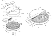
- FIG. 1 is a schematic isometric view of a rotatable connector, according to an exemplary embodiment.
- FIG. 2 is an exploded view of the rotatable connector of FIG. 1 .
- FIG. 3 is a partial, cut-way view of the rotatable connector of FIG. 1 .
- a rotatable connector 100 includes a first rotating member 10 , a second rotating member 20 rotatable relative to the first rotating member 10 , six conductive connecting members 30 , and a shaft 40 .
- the first rotating member 10 includes a first flexible printed circuit board (FPCB) 12 and a first rotating body 14 .
- FPCB flexible printed circuit board
- first FPCB 12 Six wires (not shown) are laid on the first FPCB 12 .
- One end of the first FPCB 12 is fixed to the first rotating body 14 , the other end of the first FPCB 12 is attached to a first rotating part (not shown) of a rotating mechanism (not shown).
- the first rotating body 14 is disc-shaped and includes a first surface 140 and a second surface 142 .
- the first surface 140 and the second surface 142 are on opposite sides of the first rotating body 14 .
- a first through hole 144 is defined at the center of the first rotating body 14 .
- Six circular sliding grooves 146 with different diameters are defined in the first surface 140 corresponding to the six connecting members 30 , coaxial with the first through hole 144 .
- the sliding grooves 146 encircles the first through hole 144 and are equidistant from each other.
- the first rotating body 14 further includes six conductive portions 148 positioned in the bottoms of the sliding grooves 146 respectively.
- the six conductive portions 148 are electrically connected to the six wires of the FPCB 12 respectively.
- the second rotating member 20 includes a second rotating body 22 and a second flexible printed circuit board (FPCB) 24 .
- FPCB flexible printed circuit board
- the second rotating body 22 includes a third surface 220 and a fourth surface 222 .
- the third surface 220 faces the first surface 140 .
- the third surface 220 and the fourth surface 222 are on opposite sides of the second rotating body 22 .
- a receiving groove 224 is defined in the fourth surface 222 and shaped corresponding to the second FPCB 24 .
- a second through hole 226 is defined in a bottom 224 a of the receiving groove 224 corresponding to the first through hole 144 .
- Six stepped through holes 228 are defined in the bottom 224 a of the receiving groove 224 corresponding to the six guiding grooves 146 .
- the six stepped through holes 228 are arranged in line and are equidistant from each other.
- the second FPCB 24 includes a fifth surface 240 and a sixth surface 242 .
- the fifth surface 240 faces the fourth surface 222 .
- the fifth surface 240 and the sixth surface 242 are on opposite sides of the second FPCB 24 .
- Six conductive protrusions 244 are formed in the fifth surface 240 corresponding to the six stepped through holes 228 .
- a fixing hole 246 is defined in the fifth surface 240 corresponding to the second through hole 226 and the first through hole 144 .
- One end of the second FPCB 24 is firmly received in the receiving groove 224 , and the six conductive protrusions 244 are engaged with the six stepped through hole 228 respectively so that the second FPCB 24 is fixed to the second rotating body 22 .
- the other end of the second FPCB 22 is attached to a second rotating part (not shown) of the rotating mechanism.
- Each connecting member 30 includes a conductive pole 32 and a conductive spring 34 .
- Each conductive pole 32 includes a supporting portion 322 and a connecting portion 324 extending from the supporting portion 322 .
- Each supporting portion 322 is supported in the corresponding stepped through hole 228 .
- Each connecting portion 324 extends through the corresponding stepped through holes 228 and is received in the corresponding sliding groove 146 to maintain contact with the conductive portion 148 .
- Each conductive spring 34 is received in the corresponding stepped through hole 228 .
- One end 342 of the conductive spring 34 is fixed to the supporting portion 322 , and the other end 344 is fixed to the conductive protrusion 244 .
- the shaft 40 includes a fixing portion 42 and a shaft body 44 extending from the fixing portion 42 .
- the shaft body 44 extends through the first through hole 144 , the second through hole 226 and the fixing hole 246 by clearance fit.
- the fixing portion 42 contacts the second surface 142 .
- the first rotating body 14 can rotate about the shaft body 44 with the rotation of the first rotating part of the rotating mechanism.
- the second rotating body 22 can rotate about the shaft body 44 with the rotation of the second rotating part of the rotating mechanism.
- the connecting members 30 rotate with the rotation of the second rotating body 22 .
- the connecting portions 324 are received in the sliding grooves 146 to maintain contact with the conductive portion 148 .
- electrical signals from the second FPCB 24 are transmitted to the first FPCB 12 through the conductive protrusions 244 , the connecting members 30 and the conductive portions 148 , avoiding wires getting intertwined. This is convenient.
- the amount of the connecting member 30 is not limited to six
- the rotatable connector 100 may include at least one connecting member 30 corresponding to the sliding grooves 146 and the conductive protrusions 244 .
- the sliding grooves 146 may be an arc.
- the length of the sliding grooves 146 is decided by the rotational angle of the second rotating body 22 .
Landscapes
- Coupling Device And Connection With Printed Circuit (AREA)
- Details Of Connecting Devices For Male And Female Coupling (AREA)
Abstract
Description
Claims (8)
Applications Claiming Priority (3)
| Application Number | Priority Date | Filing Date | Title |
|---|---|---|---|
| CN200810304652.9 | 2008-09-25 | ||
| CN200810304652 | 2008-09-25 | ||
| CN200810304652A CN101685936A (en) | 2008-09-25 | 2008-09-25 | Rotary connection device |
Publications (2)
| Publication Number | Publication Date |
|---|---|
| US20100075512A1 US20100075512A1 (en) | 2010-03-25 |
| US7802995B2 true US7802995B2 (en) | 2010-09-28 |
Family
ID=42038112
Family Applications (1)
| Application Number | Title | Priority Date | Filing Date |
|---|---|---|---|
| US12/538,863 Expired - Fee Related US7802995B2 (en) | 2008-09-25 | 2009-08-11 | Rotatable connector connecting two flexible printed circuit boards |
Country Status (2)
| Country | Link |
|---|---|
| US (1) | US7802995B2 (en) |
| CN (1) | CN101685936A (en) |
Cited By (5)
| Publication number | Priority date | Publication date | Assignee | Title |
|---|---|---|---|---|
| US8142200B2 (en) * | 2007-03-26 | 2012-03-27 | Liposonix, Inc. | Slip ring spacer and method for its use |
| JP2013114817A (en) * | 2011-11-25 | 2013-06-10 | Shinden Co Ltd | Slip ring device |
| US10116103B1 (en) * | 2017-12-17 | 2018-10-30 | Satyajit Patwardhan | Power connector with integrated disconnect |
| US20230024575A1 (en) * | 2021-07-23 | 2023-01-26 | Dongguan Ceesing Intelligent Device Manufacturing Co., Ltd | Unidirectional free-pulling data cable |
| US20240039220A1 (en) * | 2022-07-26 | 2024-02-01 | Shanxi Luxshare Precision Industry, Ltd. | Circuit board connection structure and rotary plug connector |
Families Citing this family (16)
| Publication number | Priority date | Publication date | Assignee | Title |
|---|---|---|---|---|
| US8079846B1 (en) | 2010-09-24 | 2011-12-20 | Mindray Ds Usa, Inc. | Rotatable electrical connector |
| US20120261155A1 (en) * | 2011-04-18 | 2012-10-18 | Liang fu-min | Connectors |
| CN104124594A (en) * | 2013-04-25 | 2014-10-29 | 英业达科技有限公司 | Rotary socket |
| DE102015207411A1 (en) * | 2014-05-27 | 2015-12-03 | Rheinmetall Defence Electronics Gmbh | Device for electrical contacting |
| MY189603A (en) * | 2015-10-27 | 2022-02-19 | Fischer Connectors Holding Sa | Multipolar connector |
| CN106099599A (en) * | 2016-08-18 | 2016-11-09 | 北京可以科技有限公司 | A kind of rotary conductive device and the rotatable spheroid of one |
| CN107864545B (en) * | 2016-09-22 | 2021-04-09 | 北京北方华创微电子装备有限公司 | Inductively coupled plasma generating device and plasma processing equipment |
| CN106505384B (en) * | 2016-11-14 | 2019-01-18 | 栾敬钊 | Twisted pair one-way expansion revolving joint |
| JP6914418B2 (en) * | 2017-08-16 | 2021-08-04 | モレックス エルエルシー | Electrical connector assembly |
| MY207882A (en) | 2018-04-06 | 2025-03-25 | Conextivity Group Sa | Multipolar connector |
| WO2019193567A1 (en) | 2018-04-06 | 2019-10-10 | Fischer Connectors Holding S.A. | Multipolar connector |
| CN109217057A (en) * | 2018-09-20 | 2019-01-15 | 珠海格力电器股份有限公司 | Connecting wire rotator and rotating assembly |
| US11404837B1 (en) * | 2018-11-06 | 2022-08-02 | SeeScan, Inc. | Robust impedance controlled slip rings |
| CN110444980B (en) * | 2019-07-18 | 2025-01-21 | 深圳市道通智能航空技术股份有限公司 | Rotating signal transmission mechanism and drone gimbal |
| CN111115467A (en) * | 2019-12-30 | 2020-05-08 | 国网山东省电力公司淄博供电公司 | Safety tower crane capable of preventing cable from winding |
| WO2022140046A1 (en) * | 2020-12-22 | 2022-06-30 | Gentex Corporation | Imager assembly with heating element |
Citations (5)
| Publication number | Priority date | Publication date | Assignee | Title |
|---|---|---|---|---|
| US5704792A (en) * | 1995-05-22 | 1998-01-06 | Hughes Aircraft Company | Spring loaded rotary connector |
| US6083022A (en) * | 1997-10-15 | 2000-07-04 | Hon Hai Precision Ind. Co., Ltd. | System for connecting daughter and mother boards |
| US7252513B1 (en) * | 2005-12-23 | 2007-08-07 | Kathrein-Werke Kg | Coaxial RF connection device electrically connected to a printed circuit board as well as associated connector unit |
| US20070218713A1 (en) * | 2006-03-17 | 2007-09-20 | Hosiden Corporation | Connector for flexible substrate |
| US20090236480A1 (en) * | 2008-03-21 | 2009-09-24 | Hong Fu Jin Precision Industry (Shenzhen) Co., Ltd | Rotary device |
-
2008
- 2008-09-25 CN CN200810304652A patent/CN101685936A/en active Pending
-
2009
- 2009-08-11 US US12/538,863 patent/US7802995B2/en not_active Expired - Fee Related
Patent Citations (5)
| Publication number | Priority date | Publication date | Assignee | Title |
|---|---|---|---|---|
| US5704792A (en) * | 1995-05-22 | 1998-01-06 | Hughes Aircraft Company | Spring loaded rotary connector |
| US6083022A (en) * | 1997-10-15 | 2000-07-04 | Hon Hai Precision Ind. Co., Ltd. | System for connecting daughter and mother boards |
| US7252513B1 (en) * | 2005-12-23 | 2007-08-07 | Kathrein-Werke Kg | Coaxial RF connection device electrically connected to a printed circuit board as well as associated connector unit |
| US20070218713A1 (en) * | 2006-03-17 | 2007-09-20 | Hosiden Corporation | Connector for flexible substrate |
| US20090236480A1 (en) * | 2008-03-21 | 2009-09-24 | Hong Fu Jin Precision Industry (Shenzhen) Co., Ltd | Rotary device |
Cited By (7)
| Publication number | Priority date | Publication date | Assignee | Title |
|---|---|---|---|---|
| US8142200B2 (en) * | 2007-03-26 | 2012-03-27 | Liposonix, Inc. | Slip ring spacer and method for its use |
| JP2013114817A (en) * | 2011-11-25 | 2013-06-10 | Shinden Co Ltd | Slip ring device |
| US10116103B1 (en) * | 2017-12-17 | 2018-10-30 | Satyajit Patwardhan | Power connector with integrated disconnect |
| US20230024575A1 (en) * | 2021-07-23 | 2023-01-26 | Dongguan Ceesing Intelligent Device Manufacturing Co., Ltd | Unidirectional free-pulling data cable |
| US11658448B2 (en) * | 2021-07-23 | 2023-05-23 | Dongguan Ceesing Intelligent Device Manufacturing Co., Ltd | Unidirectional free-pulling data cable |
| US20240039220A1 (en) * | 2022-07-26 | 2024-02-01 | Shanxi Luxshare Precision Industry, Ltd. | Circuit board connection structure and rotary plug connector |
| US12555962B2 (en) * | 2022-07-26 | 2026-02-17 | Luxshare Precision Accessory (Suzhou) Ltd. | Circuit board connection structure and rotary plug connector |
Also Published As
| Publication number | Publication date |
|---|---|
| US20100075512A1 (en) | 2010-03-25 |
| CN101685936A (en) | 2010-03-31 |
Similar Documents
| Publication | Publication Date | Title |
|---|---|---|
| US7802995B2 (en) | Rotatable connector connecting two flexible printed circuit boards | |
| JP2009004876A (en) | Electronics | |
| EP1608046B1 (en) | Electrical connector assembly for mobile terminal | |
| JP4134273B1 (en) | Rotating connector | |
| JP2008186600A (en) | connector | |
| US7394650B2 (en) | Hinge for an electronic device | |
| JP6278586B2 (en) | Coaxial connector | |
| JP5178748B2 (en) | Modem card with antenna arrangement in the corner | |
| US7393234B1 (en) | Connector with locking mechanism | |
| JP2013175459A (en) | Connector for flexible circuit cable | |
| EP2928028A2 (en) | Slip ring | |
| KR20250045500A (en) | Planar slip rings, rotating conductive assemblies and flexible data cable assemblies | |
| US7659854B2 (en) | Antennas for card devices | |
| JP6159476B2 (en) | NFC antenna assembly and mobile communication device including the same | |
| JP6157313B2 (en) | Connection device | |
| JP2011188136A (en) | Switch and communication apparatus | |
| JP2019114458A (en) | Signal transmission system and electrical connector | |
| US8079856B2 (en) | Rotatable power connector | |
| KR20040023700A (en) | Hinge connector, and circuit board connected to connector | |
| KR102282093B1 (en) | Connector for flexible cable | |
| KR200337139Y1 (en) | Connector for flexible circuit board | |
| CN101645556B (en) | Connector structure | |
| KR200419714Y1 (en) | Flexible connection structure between coaxial cable and film cable | |
| JPH09252212A (en) | Antenna device and manufacturing method thereof | |
| CN204167547U (en) | Electronic connector structure |
Legal Events
| Date | Code | Title | Description |
|---|---|---|---|
| AS | Assignment |
Owner name: HONG FU JIN PRECISION INDUSTRY (SHENZHEN) CO., LTD Free format text: ASSIGNMENT OF ASSIGNORS INTEREST;ASSIGNOR:LAI, JIN-SHI;REEL/FRAME:023074/0742 Effective date: 20090806 Owner name: HON HAI PRECISION INDUSTRY CO., LTD.,TAIWAN Free format text: ASSIGNMENT OF ASSIGNORS INTEREST;ASSIGNOR:LAI, JIN-SHI;REEL/FRAME:023074/0742 Effective date: 20090806 Owner name: HON HAI PRECISION INDUSTRY CO., LTD., TAIWAN Free format text: ASSIGNMENT OF ASSIGNORS INTEREST;ASSIGNOR:LAI, JIN-SHI;REEL/FRAME:023074/0742 Effective date: 20090806 |
|
| REMI | Maintenance fee reminder mailed | ||
| LAPS | Lapse for failure to pay maintenance fees | ||
| STCH | Information on status: patent discontinuation |
Free format text: PATENT EXPIRED DUE TO NONPAYMENT OF MAINTENANCE FEES UNDER 37 CFR 1.362 |
|
| STCH | Information on status: patent discontinuation |
Free format text: PATENT EXPIRED DUE TO NONPAYMENT OF MAINTENANCE FEES UNDER 37 CFR 1.362 |
|
| FP | Lapsed due to failure to pay maintenance fee |
Effective date: 20140928 |