US779607A - Filtering apparatus for separating solids from liquids. - Google Patents
Filtering apparatus for separating solids from liquids. Download PDFInfo
- Publication number
- US779607A US779607A US5797001A US1901057970A US779607A US 779607 A US779607 A US 779607A US 5797001 A US5797001 A US 5797001A US 1901057970 A US1901057970 A US 1901057970A US 779607 A US779607 A US 779607A
- Authority
- US
- United States
- Prior art keywords
- filter
- liquid
- layers
- outlet
- elements
- Prior art date
- Legal status (The legal status is an assumption and is not a legal conclusion. Google has not performed a legal analysis and makes no representation as to the accuracy of the status listed.)
- Expired - Lifetime
Links
Images


Classifications
-
- B—PERFORMING OPERATIONS; TRANSPORTING
- B01—PHYSICAL OR CHEMICAL PROCESSES OR APPARATUS IN GENERAL
- B01D—SEPARATION
- B01D25/00—Filters formed by clamping together several filtering elements or parts of such elements
- B01D25/22—Cell-type filters
- B01D25/26—Cell-type stack filters
Definitions
- My invention relates to that class of filters in which paper or similar pulp in a somewhat moist condition, but. not dried paper fiber, is employed as the filtering medium.
- the objects of my invention are to simplify the constructionof such a filter, to reduce the expense of producing it, and to simplify its operation; and its novelty consists in the construction and adaptation'of the parts.
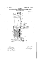
- Figure 1 is a central vertical section of a preferred form of my filteri ng elements and their adjacent parts when assembled.
- Fig. 2 is a top plan view of the same, showing parts cut away to show concealed parts.
- Fig. 3 is a vertical section in detail of a modifiedform of one of my screens or liquid-ways, and
- Fig. 4 is a plan view thereof.
- Fig. 5 is a vertical section in'detail of yet another modified form of one of my screens or liquid-ways, and
- Fig. 6 is a plan view thereof.
- Fig. 7 isacen'tral vertical section of a complete filter, showing some of the adjacent parts in elevation.
- Fig. 8 is a side elevation of a modified form of the filter prodruin and means for handling the same, some of the parts being shown in dotted outline in difierent positions from those indicated by the-full lines and the inlet-passage and connections being shown in Fig. 9 is a central vertical section of a modifiedform of two filtering elements and their connections.
- Fig. 10 is a plan view of the metal sheet 27 shown in section in Fig. 9, illustrating its connection with the hub B.
- Fig; 11 is a vertical section in detail of a form of the screen modified from that shown in Fig. 10.
- Fig. 12 is a similar view of yet another modification of this screen or liquid-way.
- Fig. 14. is a vertical section of the'filtering elements, showing-a peripheral inlet and acentral outlet. Fig.
- Fig. 13 is a vertical section of the filtering elements, shqwing 779,607, dated. January 10, 1905.
- Fig. 15 is a. similar section showing a central inlet and outlet.
- Fig. 16 is a similar section showing a peripheral inlet and a central outlet.
- ig. 17 is a similar section showing a central. inlet and peripheral outlet.
- Fig.- 18 is a similar section showing a peripheral inlet and a centraloutlet.
- Fig. 19 is a similar section showing a peripheral inlet and outlet.
- Fig. 21 is a similar section showing a central inlet and peripheral outlet, the latter communicating with a single discharge-channel; and Fig. 22 is a plan view of the same.
- Fig. 23 is a vertical section of the filtering elements, showing a peripheral inlet and outlet, each of the inlets and outlets communicating with single. inlet and discharge channels; and
- Fig. 2 1 is aplan view of the same.
- My filter is made up of a pluraiity of superimposed and congruent filter elements.
- filter elements I mean a unit consisting of one or morefilter layers of paper-pulp or similar filtering media in connection with means for supplying the. same with unfiltered liquid and draining it therefrom after filtration.
- filter layer I mean a flat plate or disk of compressed filter material having substantially plane surfaces on each side and capable of being supplied with unfiltered liquid on one side and drained from the other side.
- the unfiltered liquid must be suppiied to the filter elements and drained therefrom after filtration.
- the liquid may be supplied directly to or exude directly frbm the compressedlayer of pulp; but in no case can it be supplied to and be drained from the sarnefilter element by such means only.
- the supporting means may or may not form a part of the means for com municating with the inlet and outlet passages I also make -rose the'rein.
- the meshes of the cloth form capillary ducts which permit of the flow of the liquid.
- capillary liquid-inlet ways For instance, many filters have been provided with gas traps, vent-cocks, and the like or with means whereby the liquid entering at the bottom expelled the air from the filter at the top as it slowly Such precautions are not necessary, however, when single wire cloth screens are employed as the liquidways. It is well known that air-bubbles are driven up or down in capillary ducts by a liquid flowing through such ducts.
- Each filter element is separated from its neighbor by a single circular coarse-woven having a central circular aper ture to admit of the passage of a hub B.
- These hubs are arranged in a series one above the other and one for each filter element.
- Each hub has a wide central opening and is bored with radial holes 6,adapted to communicate with the screens C and D whenthe parts are assembled. It is also provided with a series of holes 5 parallel with its axis and which communicate with the screens E and with each other. These last-mentioned holes 5, taken all together, form an inlet-channel, and the central apertures of the hub, taken all together, form the outlet-channel, of the filter.
- the screen E is shown as if it separated the holes 5 in relation to each other. It does not, however, constitute an obstacle to the passage of the liquid which flows with projecting flanges 9, adapted to receive between them the screens C and D.
- the screens E which have a smaller central aperture than the screens'C and D, fit closely arodnd the dependent flanges of each hub and screws 7 screen of the Each hub is provided,
- each hub may be made in two pieces, divided on the plane line of the screen the parts are secured together by of the horizontal medial C. If so,
- the filter layers are formed outside of the filter in a suitable mold or former such as known in the art-for instance, a ,device similar as used in connection with-my former invention, No. 579,586, or as is used in patent specification No. 634,947.
- a suitable mold or former such as known in the art-for instance, a ,device similar as used in connection with-my former invention, No. 579,586, or as is used in patent specification No. 634,947.
- the lower layer is formed, using as'a base an-..auxiliary fine-mesh screen
- the screensC and Dam inserted, andthen the upper layer is'f-or-med.
- the pulp of the'upper layer being wet when it is brought into contact with that of the lower layer beyond the circumference of the screens C and D, the fibers of these two layers are caused to be interlaced in the annular area of contact above referred to.
- the inwardly-projecting portion 2 of the ring A
- the outer surfaces of the hub B are made smooth and without rough or projecting parts, so that the compressed pulp tends to cling to them closely. There is thus avoided any tendency for the unfiltered liquid to creep along the line ofjunction between the pulp and the metal.
- Fig. 7 is illustrated. the method of as sembling the filter elements.
- the hubs B are mounted one above the other, exact centering being secured by the engagement of their dependent members. The alinement of the parts It will be noticed also that I is further assisted by the engagement of the when the filter is valve-controlled I able pressure.
- All of the screens E are connected with the holes 5, which form the vertical inlet-channel of the filter, and all of the screens C are connected with the radial holes 6 and through them with the centers of the hubs, which together form the vertical outlet-channel of the filter.
- the filter elements are assembled above a base H, made of cast metal or other suitable material and provided with a valve-controlled inlet-passage l, communicating with the lowermost screen 0, and also provided'with .
- Fig. 8 is illustrated the means employed for tighteningthe filter.
- Two upright posts L and L are secured to the base H.
- L Onone of them, L, and adapted to swing on a hinge or pintle is secured a yoke N, provided .witha centrally-threaded aperture adapted to engage with a vertical screw K, to which is secured at its upper end a hand-wheel and at its lower end a cover Gr.
- the hand-wheel is turned until the cover is forced down on the uppermost ring A and fits tightly.
- some other devices useful provided with an external drum or cover and which will be hereinafter described.
- the operation of the filter constructed as above described is as follows: The turbid liquid is let into the inlet-passage I under suit- Thence it flows to the lowermost screen E and through the holes 5 5 and the diflerent inlet liquid-ways or screens E until it reaches all of the filter layers M. Forced by the pressure back of it, it permeates and. penetrates the filter layers until it reaches the protecting-screens D. It then passes through these screens to the outlet fluidways formed by the screens C and thence through the holes 6 6 to the central apertures of the hubs and the outlet-passage 0.
- the screens C C may be used as outlet liquid-ways without the protectingscreens D D; but the use of the latter is de- "rings A and that the greater the pressure the tighter the filter mass is compressed-a result heretofore much desired. but not obtained in any form of filter known to me.
- the width of the flange 9 of the hub should be as wide as the thickness of the filtering layer in contact with it. If it would be less,
- Figs. 3 and 4 flat bars 31 of diflerent lengths are radially arranged to form a circular cribwork, cross-wires 32' serving to connect the bars 31 where necessary to keep them in position.
- the longest bars extend inward and are placedbetw'een the flanges 9 of the hub B. It will be seen that to a certain extent this cribwork performs the same function as the screens C-that is, it supports the filter mass and forms an outlet liquid-way for the clarified liquid; but it is not a capillary way.
- a circular sheet of flannel D is placed on each side of the crib.
- Figs. band 6 is shown another modification of the means provided for the outlet fluidway.
- the supporting-screen in this case is made of an open-work circular plate ot metal or other suitable material engaging with the flanges 9 of the hub B and provided with radialmembers 34: on I its lower side and circular concentric members 33 on its upper side.
- This plate is likewise provided with protecting layers of flannel D, placed on each side thereof.
- Figs. 9 and 10 are illustrated further modified forms employed for the inlet and outlet liquid-ways'of the filter element.
- a The in- 11, and 12 are illuslet-way is made of a screen of wire-cloth E,
- the slots 28 communicate with the radial holes 6 of the hub B.
- On each side of the sheet 27 is arranged a finewirecloth screen 29.
- flannel sheets D are at their inner edges engaged by lips 9, formed on the flanges 9" of the hub B.
- the flannel serves as a protecting-sheet to prevent the eseapeof the fibers.
- the screens 29 serve as capillary outlet liquid-ways and the radial slots 28 of the plate 27 as an outlet channel additional to that afforded byholes 6.
- FIG. 11 a further modified form of the outlet liquid-way is shown in section.
- the intermediate fine wire-cloth screens 29 (shownin Fig. 10) are dispensedwit'h entirely.
- Fig. '12' is illustrated yet another modifi cation of this partofthe apparat'u's.--
- the screen, 6'. is formed of double woven-Wire cloth of relatively wide mesh and is protected icy-flannel; screens D" and engages with the flanges9 ofthe hub B, as heretofore described.
- d'eep circular groove 9 to admit of the recep- "3 doublygrooved flange is also shown with the 1 shallow groove notqu'ite so deep as that shown tion ofthe'fgplate 27,, In Fig. 11 a similar in Fig. 9'.”
- the filter elements are of the ring A", in which it is provided with an inwardly-extending flange 59, grooved to admit of the reception of the plates C. I am therefore able to make the flange 9 of the hub smaller, because not so much strength is needed to support the filter element when the screen C is supported at its periphery as well as at its center.
- filter elements is either dispensed with entirely, asshown in Fig. 18, or is-reduced to the form A shown in Fig. 1'6, in which it is provided with holes 5, like theholes 5 with which the hub B was formerly provided and whlch together constitute a peripheral inletchannel to the screens E, a flange 19, suitably grooved, being provided to properly-support the drainage-screens C and their protectingor the rings A are reduced to a yet simpler form, as shown in Fig. 14, where it consists of a vertically-placed annulus A, provided with an inwardly-projecting flange E being interposed between each pair of rings and an inlet-channel W being formed between the outside surfaces of j therings and an encircling drum R.
- FIGs. 9, 13, 14, 15, 16, 17, 18, 19, 20, 21, 22, 23, and 24 are illustrated certain modified forms of the ring A encircling the filter elements.
- this ring is shown as consisting of a vertically-placed annulus forked at its bottom edge and provided with a groove adapted to receive the gasket 1 and with an inwardly-projecting member 12, adapted to prevent the filter mass from s ipping downward-
- Fig. 9 is shown a slight modification of Fig. 1 in that the external walls of the rings are made smooth and together constitute a practically unbroken cylindrical surface.
- Fig. 15 the ring is shown as asingle ver-' tically-placed annulus A with an inwardlyprojecting grooved flange 59, adapted to receivea screen, as C, all the rings together constituting a cylinder with an externally
- Fig. 14 substantially the same'construction of-the ring is shown as in Fig. 15 except that the top and bottom edges of the rings A do not touch each other, but are separated to admit of the passage ,of the screens E E, which screens communicate under such circumstances with an annular space between the external surfaces of themihgsla nd an inclosing drum R, surrounding all. ofithe filter elements and placed, a 'slight distance therefrom. 1
- Fig. 17 is shown a 'inodifiefl form of the ring A, in whichit isprovided with an inwardly-extending flange 69, which is not only grooved to admit of the reception of'a screen,
- Fig. 20 a construction in-which addieach ring is provided with an outer vertical member a, an inner vertical member a, with an annular space between themexcept at annular area of contact a provided in turn with vertical holes 5", adapted to communicate with radial holes 6, which in turn communicate with the grooves of inwardlyextending flanges 69, adapted to receive and support screens C.
- the screens, radial holes 6, vertical holes and the annular passage between the outer and inner members ofthe ring constitute the outlet liquid-way and. the discharge-channel of the filter elements.
- Fig. 19' is shown essentially thesame construction of the ring A. as that just described as shown in Fig. 20; but ,itis combined with the external drum It, afiording an additional annular passage W outside of the external surface of the rings.
- the radial holesfi communicating with'the grooves of the inwardly-extending flanges 69, are drilled all the way through both members of the ring to afiord a communication between the screen (3,. sup-- ported in the flange, and the annular passage between the outer surface of the rings and the external drum R. 1
- the vertical holes communicating in this case with the screens E,ivhich form the inlet liquid-ways of the'filter and the radial holes communicating with the screens 0, which form the outlet liquid-ways of the filter.
- the inlet and outlet channels of the filter are apertures.
- Figs. '21 and 22 is shown another modified form of the ring in which it consists of a vertically-placed annulus A, provided with an inwardly-extending groovedfiange' 79,
- Figs. 23 and 2e a modification ofthe construction illustrated in Figs. 21 and 22.
- thering A is pro-' .vided with two sets'of ears 36 and 37,.suitably filter be fed apertured, the set 37 constituting an inletchannel and the set 36 an outlet-channel for.
- the filter elements when assembled.
- the wallsof the intermediate vertical member of the ring are apertured at difierent points, as S S, to afl'ord acommunication 37 and the screens E, constituting the inlet. fluid-waysof the filter.
- the inlet and outlet channels are peripheral and the central hub is omitted.
- the inlet-channel is peripheral I and theoutletohannelcentral.
- the inlet and tl t channels are bOllll central;
- the combination shown 3 In a filter, the combination with a'plu- 75 in section in Fig. 18 has been employed for rality of circular filter elements, each consistthe filterel ements.
- the screens E therefore ing of two flat filtering layers of fibrous ma-- extend to the outer edge of the cylindrical terial, interlaced with each other at their pebody formed-by the different filter elements.
- the drum R which has been'formed virtually from entering between said layers, and con: 0 by the consolidation of the different vertical nected at their centers by means of non-porous rings A into one piece, is adapted to encircle material, ali'ording a'continuous communicatand surround the filter elements when assem: ing passage for all the filter elements, in Congressd.
- the problem to bination with liquid-ways for draining oil the 20 be solved was to make-the application of a filtered liquid and means for supplying the 5 drum of this kind possible while not obstructfilter elements with unfiltered liquid. 1 ing access to all of the parts while assembling 4. In a filter, the combination of two fibrous them.
- one of the uprights L, filter layers, of inletliquid-ways, each consistpreviously referred to, is made hollow and ingof single-woven wire screens, where loa 5 forms a cylinder for a long piston P.
- a cated between the effective parts of said filter '9 "hydraulic pumpQofusual construction serves layers, with means-for supplying the inletfor raising thepiston.
- a chain 21 is fastened wayswithunfiltered liquid and conducting the at one end to the yoke N and at the other end filtered liquid from the filter layers.
- the of singlecoarsewoven screens in combination 95 hydraulic piston carries at its upper end a with a finer. protecting woven screen in conbracket 20,supporting two pulleys over which tactitherewith, arranged parallel and in conthe chain 21 is adapted to pass.
- a stop-lug tact with two filter layers drained' thereby, 23, fastened upon the chain, is adapted to enand means for supplying unfiltered liquid to gage with a rearwardly-projecting member 24 the filter layers and for carrying ofl the'c'lari- I of the bracket 20, and thus limit its upward fied liquid frorn'the outlet liquid-way. 'rnovement. .If the chain 21 were not provided- 6.
- a filter the combination with a plurality of filter elements, each composed of two the fibers of the .same being interlaced in an annular area of contact but not interlaced with the layers of the neighboring filter elements, of means for liquid-way for separating'the neighboring elements consist-. ng of a single wire-cloth adapted to form a the supply of theliquid, with means for supplying the inletliquid-ways with] unfiltered liquid and conductingthe filtered liquid from the outlet liquid-ways.
- a' filter a base, a plurality'c'f filterelements, eachconsisting of .twolayers of compressed pul'p,'and touching each'other in an annular area of contact, liquid conductOrs adapted to soparate the filter-layersof neig'h-j porous means for erence to the base, in combination with means for supplying the inlet liquid-ways with unfiltered liquid and cpnduc'ting the filtered'liqe uid from the outlet liquid-ways,
- acircular Woven liquid-conductor in contact with two filter layers, saidliquid-conductor having concentrical and ringshaped flanges, increasing at their places of connection the thickness of the liquid-con- 8 ductor, and adapted to more compress the fibers of the filtering layers than the rest of the liquid-conductors.
- aliquid-conductorfor clear liquid having contact-surfaces arranged parallel to the filtering layer and projecting more into the latter than the rest of said liquid-conductor
- liquid-conductor in contact with two filte'r layers of compressed fibrous pulp, said liquid-conductor ihaving concentricaland ring-shaped flanges, increasing at their places of connection the thickness of the liquid-conductor and adapted to more .compress the fibers of the filteringlayers than the 1 rest of theliquid-conductors, with means for supplying the inlet liquid-conductors with unfiltered liquid and conducting the filtered liquid from the outlet liquid-conductors.
- a filter the combinationof two filtering layers of compressedfibrous pulp, of draining or supplying said filter layers, cons sting of single woven screens, where located" between the efiective part of said layers, with means for supplying the inunfiltered liquid and conliquid from the outlet liqducting the filtered uid-ways.
- liquid-ways each consisting of singl coarsely-woven screens parallel to and in contact with finer protecting woven screens, each of the finer screens in contact, with a filter layer, and means for supplying the inlet liquid-ways with unfiltered liquid and conducting the filtered liquid from the outlet liquid-ways.
- a filter the combinatlon with a plulayers, said liquidfor supplying the layers of compressed, pulp, the fibers of the same being interlaced in an annular area of contact, but not interlaced with the layers of neighboring filter elements, of liquid-conductors adapted to separate the neighboring filter elements, and of means of supporting the filter elements, consisting ofoa liquid-conductor connected to a concentrical hub with openings for the supply or discharge of the liquid passing through the filter, and of means inlet liquid-ways with unfiltered liquid and conducting the filtered liquid from'the outlet liquid-ways.
- a filter the combination with a plurality of filter elements, each composed of two layers of compressed pulp, the fibers of the same touching each other in an annular area of contact, but not touching the layers of neighboring elements, of liquid-conductors adapted to separate the neighboring filter elements, and of means for supporting the filter elements, consisting of a liquid-conductor connected to a concentrical hub with openings for the supply or discharge of the liquid passing through the filter, of means for sup- .plying the inlet liquid-ways with unfiltered liquid and conductingthe filtered liquid from the outlet liquid-ways.
- Y 1 the combination with a plurality of filter elements, each composed of two layers of compressed pulp, the fibers of the same touching each other in an annular area of contact, but not touching the layers of neighboring elements, of liquid-conductors adapted to separate the neighboring filter elements, and of means for supporting the filter elements, consisting of a liquid-conductor connected to a concentrical hub with openings for the supply or discharge of the liquid passing through the filter
- filter elements consisting of two filter layers of compressed pulp, the fibers of which are interlaced in an annular area of contact, but not interlaced with the layers of the neighboring elements, of means for supplging the filter elements with unfiltered liqand conducting the filtered liquid therefrom.
- filter elements consisting of two filter layers of compressed pulp, the fibers of which are interlaced in an annular area of contact at their periphery, but not interlaced with the layers of the neighboring elements, of means for supplying the filterelements with unfiltered liquid and conducting the filtered liquid'therefrom.
- filter elements consisting of two filter layers of compressed pulp, the fibers of which touch each other in an-annular area of contact, but not touching the layers of the neighboring filtering elements, of ,means for supplyingthe filter elements with unfiltered liquid and conducting the filtered liquid there- I from.
- filter elements consisting of j two filter layers of compressed pulp, the fibers of which touch each other in an annular area of contact atv their periphery, but not touching the layers of the neighboring filtering elements, of means for supplying the filter elements with unfiltered liquid and conducting the filtered liquid therefrom.
- a filter in combination, a plurality of filter elements, each composed of two layers of compressed touching each other in an annular area of contact at the periphery, and are more compressed at their centers.
- a filter the combination with a pluralityof filter elements, each'composed of two layers of compressed pulp, the fibers of the same being interlaced in an annular area of contact, but not interlaced with the layers of pulp, the fibers of the same' the neighboring filtering elements, of means adapted to prevent the passage, between two neighboring elements, of unfiltered liquid to the filtered side.
- a filter the combination with a plurality of filter elements, each composed of two layers of compressed pulp, the fibers of the same touching each other inan annular area of contact, but not touching the layers of the neighboring elements, of means adapted to prevent the passage between two neighboring elements, of unfiltered liquid to the filtered "side.
- a filter the combination with a plurality of filterIelements, each composed of two layers of compressed pulp, the fibersof the same touching each other in an annular area IOO of contact, but not touching the fibers of neighboring layers but connected with nonporous means adapted to prevent the passage of unfiltered liquid between two neighboring filtering elements into the clear side.
- a filter the combination with a plurality of filter elements, each composed of two layers of compressed pulp, the fibers of the same touching each other in an annular area unfiltered liquid between two neighboring filperiphery'but not interlaced of means adapted to preventthe .tween them the sheets of Woven-wire wire cloth and means 40.
- a filter a filter
- a filter in a filter, a plurality of filter elements, each supplied and drained by capillary liquidways consisting of woven-wire cloths, means for supporting said cloths, consisting of central hubs each provided with passages connecting with both said capillary liquid-ways, and of means for supplying the inlet liquidways with unfiltered liquid and conducting the filtered liquid from the outlet lirpiid-ways.
- a filter in a filter, a plurality of superimposed filter elements consisting of filter layers, each supplied and drained by liquid-conductors consisting of woven-wire cloths, central hubs, each provided with projecting flanges arranged in pairs and adapted to support becloth, and of means for supplying the inlet liquidways with unfiltered liquid and conducting the filtered liquid from the outlet liquid-ways.
- a filter in a filter, a plurality of superimpose filterelements, consisting of filter layers, eac 1 supplied and drained by liquid-conductors consisting of woven cloths, central hubs, each provided with projecting flanges arranged in pairs and adapted to support between them sheets of woven cloth, each hub being provided with apertures afi'ording communication between the said cloths so supported, and passages within the hubs.
- a central hub provided with horizontally-projecting flanges in pairs adapted to support between them sheets of wovenaffording communication between said cloth and passage within the hub of filter layers, and means for supplying the/filter layers with unfiltered liquid and conducting the filtered liquid therefrom.
- central hub comprising an inner annulus, flanges projecting therefrom in pairs and adapted to embrace between them sheets of woven-Wire cloth, and provided with passages leading from the interior of the annulus to the spaces between the flanges, of filter layers, and means for supplying the filter layers with iinfiltered liquid and conducting the filtered liquid therefrom.
- a fiiter comprising a plurality of filter elements, each supplied and drained by capillary liquid-ways consisting of woven -wire cloths, means for supporting said cloths consisting of central hubs provided with apertures, connecting the interior thereof with both of said cloths, and provided also with smooth external surfaces whereby a close contact is secured between the filter mass and the said surfaces, and means for supplying the inlet liquid-ways with unfiltered liquid and conducting the filtered liquid from the outlet liquid-Ways.
- a central hub consisting of an inner annulus, flanges projecting therefrom in embrace between them sheets or" woven-wire cloth, and provided with passages leading from the interior of the annulus to the space between the flanges and other passages not communicating with those first named, the latter being formed within the walls of the hub, in combination with filter layers, and means for supplying the filter layers with unfiltered liquid and conducting the filtered liquid therefrom.
- a central hub consisting of an inner annulus, flanges projecting therefrom in pairs and adapted to embrace between them sheets of woven-wire cloth and provided with passages leading from the interior of the annulus to the spaces between the flanges and other passages not communicating with those first named, also formed within the walls of the hub and adapted to communicate with sheets of woven-wire cloth held between each pair of hubs when the latter are arranged in vertical series.
- lna filter the combination with central hubs, each provided with projecting flanges in pairs adapted to embrace between them sheets of woven-wire cloth, and provided with passages leading from the interior of the annulus to the space between the flanges and other passages not communicating with those first named, formed within the walls of the hub and adapted to communicate with sheets of woven-wire cloth held between each pair of hubs when the latter are arranged in vertical series, of filter layers arranged between the sheets of woven-wire cloth and means for supplying the same with liquid.
- a series ofsuperimposed central hubs each provided with an inner annulus, a pair of horizontal projecting flanges with asuitable space between them and an upwardly-projecting annular flange, in combination with filter layers, and means for supplying the filter layers with unfiltered liquid and conducting the filtered liquid therefrom.
- a series of superimposed central hubs each provided with an inner annulus, a pair of horizontal projecting flanges, an upwardly-projecting annular flange and a dow nwardly-projeeting annular flange, in combination with filter layers, and means for supplying the filter layers with unfiltered liquid-and conducting the filtered liquid therefrom.
- the upwardly-projecting flange on one hub and the downwardly -projecting flange on the hub above it being adapted between them to embrace and support a sheet of woven-wire cloth, in combination with filter layers, and means for supplying the filter layers with unfiltered liquid and conducting the filtered liquid there romnfic Mfr/j filtered liquid and of superimposed central hubs, each provided with an innerannulus, horizontally-projecting, upwardlyprojecting and downwardlyprojecting'flanges, of a woven-wire-cloth liquid conductor embraced between.
- a central hub cbnsisting of an inner annulus, horizontal flanges projecting therefrom in pairs and upwardly and downwardly projecting annular flanges providing between their inner surfaces and the outer surfaces ofthe wall of channelsand means by which such channels communicate with each other,-in combination with filter layers, and means for supplying the filter layers with unfiltered liquid and conduct ing the filtered liquid therefrom.
- each hub consisting of a central inner annulus and provided with a pair of horizontal projecting flanges and upwardly and downwardly projecting annular flanges, the latter being adapted to not quite touch each other when the hubs are assembled in vertical series, in combination with filter layers, and of means for supplying the filter layers with unfiltered liquid, and conducting the filtered liquid therefrom.
- each hub consisting of an inner annulus and provided with upwardly and downwardly projecting annular flanges whereby there is constituted between the inner surfaces of such annular flanges and the outer surfaces of the wall of the inner annulus annular liquid-channels, which are provided with means for communicating with each other, consisting of a series the inner annulus, liquid-' said flanges,
- a filter the combination with a central hub,comprising an inner annulus provided with a pair of horizontal projecting flanges and. radial passages between the interior of the annulusand a space between said flanges, of an outlet fluid-way consisting ofwoven gauze held between said flanges, filter layers arranged on each side of said outlet fluid-ways, inlet, fluid-ways arranged in contact with said filter layers, and means for supplying the inlet fiuid-ways with unfiltered liquid and conducting the filtered liquid from the outlet fluid-way.
- a filter the combination with a central hub comprising an inner annulus provided with a pair of horizontal projecting flanges and radial passages between the'interior of the annulus and the space between said v flanges, of anoutlet fluid-way consisting of woven gauze held between said flanges, a layer of filter mass arranged on each side of gauze and interlaced in an annular area of contact beyond the periphery thereof, inlet fluid-ways consisting of woven gauze supported by and embraced between the said hub and a similar hub and means for supplying the inlet fluidways with unfiltered liquid and conducting the filtered liquid. from the outlet fluid-ways.
- a filter the combination with a plurality of central hubs, each consisting of an inner annulus provided with a pair of horizontal between the interior of the annulus and the space between the flanges, of an outlet fluidway consisting of woven cloth held between a layer of filter mass arranged on each side of said woven cloth, inlet fluidways arranged on the other sides of said filter layers and held in position by projecting flanges on neighboring hubs when the latter are arranged in vertical series, and means for supplying the inlet fluid-ways with liquid, consisting of vertical channels arranged within the walls of the hub.
- a central hub consisting of an inner annulus, a pair of horizontal projecting flanges, passages communicating between the interior of the annulus and-the space between the flanges, and an 'upwardly-project ing flange, which doesnot reach'as high as with filter layers, the filter layers conducting the filtered liquid therefrom.
- a filter the combination with a plurality of circular filter elements, each consisting of two flat fibrous filtering layers, interlaced with each other at their periphery so as to prevent unfiltered liquid from entering between said layers, and connected at their centers by rigid means affording a communicating passage for the clear liquid of all the filter elements, in combination with liquidways for draining off the filtered liquid and means for supplying the filter elements with unfiltered liquid.
- a filter in a filter, the combination of a plurality of filter elements, each consisting of a fibrous filtering medium, embedded in which is a circular disk-shaped liquid-conductor for the-draining of the clear liquid, consisting'of wire screen, and of means ofi'ering no greater porosity than said filtering medium, for supl n. l
- liquidconductor in a ductor consisting of coarse-wire screen and fiber-retaining screen, said liquidconductor interposed between and in contact with two filtering layers of compressed fibrous pulp.
- a filter in combination, a liquid-conductor consisting of coarse-wire screen and fiber-retaining screen, said liquid conductor interposed between and in contact with two filtering layers of fibrous material.
Description
PATENTED JAN. 10, 1905.
APPLIOATIOI FILED APR. 29, 1901.
6 SHEETS-SHEET 1.
PATENTED vJAN. 10, 1905.
Y K. KIEFER. PILTERING APPARATUS FOR SEPARATING SOLIDS PROM LIQUIDS.
APPLIUATION FILED APR. 29 1901.
6 BHEETSSHEET 2 MOCQMZA No. 779,607. PATENTED JAN. 10, 1905.
K. KIEPER.
FILTERING APPARATUSFOR SEPARATING SOLIDS FROM LIQUIDS. APPLIOATION FILED A311. 29. 1901.
B SHEETS-SHEET 3 PATENTED JAN. 10, 1905. K. KIBFBR. PILTERING APPARATUS FOR SEPARATING SOLIDS FROM LIQUIDS.
APPLIOATIOR FILED APR. 29. 1901.'
No. 779,607. PATENTED JAN. 10, 1905 K. KIEFER.
FILTERING APPARATUS FOR SEPARATING SOLI DS PROM LIQUIDS.
' APPLICATION FILED APR. 29, 1901.
'3 SHEETS-SHEET 5.
'1 J9 z I 5 W1 7 ESSES IN VEN TOR PATENTBD JAN; 10, 19Gb.
' K. KIEFER. FILTBRING APPARATUS FOR SEPARATING SOLIDS PROM LIQUIDS.
APPLICATION FILED APR. 29. 1901.
6 SHEETS-SHEET 6.
INVENTOR h No. tracer.
NITED STATES Patented anuary 10, 1905.,
KARL KIEFER, or OINCINNATLFOHIO FILFERING' APPARATUS. FOR ,SEPARATING souos FROM LIQUIDS.
SPECIFICATION forming part of Lettefs Patent No.
' ,App1ication filed April, 29, 1901. Serial Nd. 67,970. g I I T all whom it may concern:
Be it known that I, KARL-KIEFERJI. citizen of the United States, residing at Cincinnati, Hamilton county, Ohio, have invented certain new and useful Improvements in Filtering Appa- .ratus for Separating Solids from Liquids, of
which the following is a specification.
My invention relates to that class of filters in which paper or similar pulp in a somewhat moist condition, but. not dried paper fiber, is employed as the filtering medium.
The objects of my invention are to simplify the constructionof such a filter, to reduce the expense of producing it, and to simplify its operation; and its novelty consists in the construction and adaptation'of the parts.
vided with an incasing vertical section.
in the drawings, Figure 1 is a central vertical section of a preferred form of my filteri ng elements and their adjacent parts when assembled. Fig. 2 is a top plan view of the same, showing parts cut away to show concealed parts. Fig. 3 is a vertical section in detail of a modifiedform of one of my screens or liquid-ways, and Fig. 4 is a plan view thereof. Fig. 5 is a vertical section in'detail of yet another modified form of one of my screens or liquid-ways, and Fig. 6 is a plan view thereof. Fig. 7isacen'tral vertical section of a complete filter, showing some of the adjacent parts in elevation.
Fig. 8 is a side elevation of a modified form of the filter prodruin and means for handling the same, some of the parts being shown in dotted outline in difierent positions from those indicated by the-full lines and the inlet-passage and connections being shown in Fig. 9 is a central vertical section of a modifiedform of two filtering elements and their connections. Fig. 10 is a plan view of the metal sheet 27 shown in section in Fig. 9, illustrating its connection with the hub B. Fig; 11 is a vertical section in detail of a form of the screen modified from that shown in Fig. 10. Fig. 12 is a similar view of yet another modification of this screen or liquid-way.
a peripheral inlet and outlet. Fig. 14. is a vertical section of the'filtering elements, showing-a peripheral inlet and acentral outlet. Fig.
Fig. 13 is a vertical section of the filtering elements, shqwing 779,607, dated. January 10, 1905.
15 is a. similar section showing a central inlet and outlet. Fig. 16 is a similar section showing a peripheral inlet and a central outlet.
ig. 17 is a similar section showing a central. inlet and peripheral outlet. Fig.- 18 is a similar section showing a peripheral inlet and a centraloutlet. Fig. 19 is a similar section showing a peripheral inlet and outlet. Fig.
- 20 1s a similar section showing a central inlet and peripheral outlet. Fig. 21 is a similar section showing a central inlet and peripheral outlet, the latter communicating with a single discharge-channel; and Fig. 22 is a plan view of the same. Fig. 23 is a vertical section of the filtering elements, showing a peripheral inlet and outlet, each of the inlets and outlets communicating with single. inlet and discharge channels; and Fig. 2 1 is aplan view of the same.
My filter is made up of a pluraiity of superimposed and congruent filter elements.
, By the words filter elements I mean a unit consisting of one or morefilter layers of paper-pulp or similar filtering media in connection with means for supplying the. same with unfiltered liquid and draining it therefrom after filtration.
By the words filter layer I mean a flat plate or disk of compressed filter material having substantially plane surfaces on each side and capable of being supplied with unfiltered liquid on one side and drained from the other side.
The unfiltered liquid must be suppiied to the filter elements and drained therefrom after filtration. In either case the liquid may be supplied directly to or exude directly frbm the compressedlayer of pulp; but in no case can it be supplied to and be drained from the sarnefilter element by such means only. There must be employed in addition fluid-ways. If the liquid is supplied directly, it must be drained through such a fluid-way, and if it is drained directly from the filter-layer it must be sup-" plied through such a fluid-way. it av point to separate each filter element from its neighbor and to support it independently of its neighbor. The supporting means may or may not form a part of the means for com municating with the inlet and outlet passages I also make -rose the'rein.
I will first describe some of the general features of my invention. In the first place, I desire to call attention to the fact that I use a single coarse wire-cloth as a means for supplying the unfiltered liquid to and drawing the clarified liquid from the filter elements.
In filters as heretofore made and'known to me several constructions have been used to produce interstices or fluid-ways between two layers of semimoist and fibrous filter mass. Perforated metal sheets in combination with woven-wire fabrics have played an important part in producing such fluid-ways.
The use of a single woven fabric, however such' as, for instance, a coarse wire-clothhas to my knowledge not heretofore bbtained as a means of distributing liquid to a'filtering medium consisting of plastic compressed pulp, such as paper-pulp freshly compressed, because it was thought that paper-pulp was plastic enough to fill out the interstices of the Woven fabric. In the course of my investigation into this art I discovered that even when a single woven-wire cloth was used the filter mass of a certain consistency and moisture could not with the customarypressures employed be pressed so far between the interstices of the wire-cloth as to prevent the passage of liquid from one end of thecloth to the other or, infact, as to prevent its passage in any direction within the cloth. In other words, the meshes of the cloth form capillary ducts which permit of the flow of the liquid. I arrived, moreover, at another important result by using such capillary liquid-inlet ways. Heretofore When a filter was started it was necessary to vent it or to expel the air from within it by means of the entering liquid or by means of some special device provided for that specific purpose. For instance, many filters have been provided with gas traps, vent-cocks, and the like or with means whereby the liquid entering at the bottom expelled the air from the filter at the top as it slowly Such precautions are not necessary, however, when single wire cloth screens are employed as the liquidways. It is well known that air-bubbles are driven up or down in capillary ducts by a liquid flowing through such ducts. Under such conditions the consistency and cohesion of the liquid prevent air-bubbles from asserting their minor specific gravity in such a small space and they must be carried along with the stream of fluid and cannot collect or interfere With the filtering operation. I have utilizedthis principle and have constructed the fluid-Ways throughout my filter, Where they were necessary, in such a manner as to form these capillary ducts, and I have thereby gotten rid of the difficulty arising from the presence of air,
within the filter. At the same time I have securedthe advantage by using coarse wirecloth of the employment of a material which is cheap, light, and not readily gotten outof order.
. ers, the
the fiber will settle so rraeor Where I speak of coarse wire-cloth I mean a mesh of two and one-halfto four openings to the inch, whereby the wire will have. a thickness of from .080 to .125 of an inch. When I speak of fine wire-cloth, which I also call frequently fiber-retaining cloth, I I
mean having meshes from thirty to fifty to the inch and a wire of the thickness of. .015 of an inch. This, fine wire mesh is usually woven in a manner which is called twilledf This manner admits of using very strong wire, offering suficient permeability to the water,
and it is this kind of cloth whichI preferably use in this filter and which has given the results as described. No difficulty arises from the use of such a single woven-wire cloth as an inlet liquid-way either when it is placed between two layers of compressed filter mass or between some other pliable substance and a layer of such filter mass. The fibers of the compressed layers'do not singly protrude and do not tend to choke up the interstices in the woven-wire cloth. Moreover, the current of the incoming flowingliquid is away from the cloth and toward the filter layer'on either one or both sides, and the tendency of its action is therefore further to compress the fiber; When, however, asingle coarse-woven wirecloth is to be used for the outlet liquid-way, a difficulty arises. As the outlet liquid-way is to be embedded between two filteringlayfilter mass would have to be poured against the outlet wire-cloth in a thin state. In this conditionthe thin mixture would run through the meshes of the coarse wire-cloth. I therefore have to protect the coarse wirecloth with a finer wire-cloth of the described dimensions. This fiber-retaining wire-cloth is not fiber-retaining in the absolute sense; but when the fiber is mixed in the consistency in which it is customary to use'it in pulp-filters quickly upon the wirecloth that there is no loss of the fiber, and this fine mesh of wire-cloth may be practically called fiber-retaining. I also may use vegestill table or animal fiber-retaining cloth-such as, Y
for instance, wool flannel or felt. I also describe hereinafter in this specification sundry modified forms of these inlet and outlet fluidways, which will be made the subject of separate applicationsfor patents.
In the practical construction of my filter I Each element is supported independently and separated from' its neighbor by 'the screen which forms the inlet fluid-way, and the two make the filter elements in pairs of layers.
layers of thepair are separated partly but not.
wholly by the screen which forms the outlet fluid-way- The screens and filter elements are supported either by central or peripheral means, which constitute also the meansof communication between the fluid-ways and the in: let and outlet passages of the filter.
It will'be understood, of. course, that while aisingle filter element might be employed, yet
. Waco? in practice my filter is made up of a plurality of such elements assembled in asuitable framework, with inlet and outlet passages common' Letters Patent.
" bling the elements arated from each other-by means of two finewire or cloth circular screens D, between which is a coarse-wire-cloth screen (1 Where they are not so separated, these two layers have their fibers interlaced in an annular area of contact beyond the circumference of the screen C. The filter. mass M is encircled by a ring A, made of metal or any suitable material and forked at the bottomto form a groove in which is inserted a gasket 1. These I grooves serve also to maintain the alinement wire screen E,
through its meshes.
of the superimposed rings, which together form an encircling shell for the filter elements.
Each filter element is separated from its neighbor by a single circular coarse-woven having a central circular aper ture to admit of the passage of a hub B. These hubs are arranged in a series one above the other and one for each filter element.
Each hub has a wide central opening and is bored with radial holes 6,adapted to communicate with the screens C and D whenthe parts are assembled. It is also provided with a series of holes 5 parallel with its axis and which communicate with the screens E and with each other. These last-mentioned holes 5, taken all together, form an inlet-channel, and the central apertures of the hub, taken all together, form the outlet-channel, of the filter. In Fig.1 the screen E is shown as if it separated the holes 5 in relation to each other. It does not, however, constitute an obstacle to the passage of the liquid which flows with projecting flanges 9, adapted to receive between them the screens C and D. The screens E, which have a smaller central aperture than the screens'C and D, fit closely arodnd the dependent flanges of each hub and screws 7 screen of the Each hub is provided,
between parallel projecting members 3 and; on each hub and corresponding downwardlyprojecting members on the hub above it. Beneath the lowermost rim of each hub is se-v cured a gasket 8. This gasket cannot, however, become unduly com pressed, as the members 3 and 4 aremade of such a size that they will touch the corresponding members of the adjacent hub before destructive" compression of the gasket can occur. Each hub may be made in two pieces, divided on the plane line of the screen the parts are secured together by of the horizontal medial C. If so,
The filter layers are formed outside of the filter in a suitable mold or former such as known in the art-for instance, a ,device similar as used in connection with-my former invention, No. 579,586, or as is used in patent specification No. 634,947. First, the lower layer is formed, using as'a base an-..auxiliary fine-mesh screen Then the screensC and Dam inserted, andthen the upper layer is'f-or-med. The pulp of the'upper layer being wet when it is brought into contact with that of the lower layer beyond the circumference of the screens C and D, the fibers of these two layers are caused to be interlaced in the annular area of contact above referred to. The inwardly-projecting portion 2 of the ring A,
which forms one wall of the gasket-groove of such ring, serves as a support for the filter mass M to prevent it from'slipping downward. In order to transport the finished filter element from the packing apparatus to the filter proper, it is carried between two coarse screens E, which are clasped together with both hands. The exchange from the auxiliary packing apparatus to the separating-screen E is effected by reversing the filter elements, whereupon the substitution can take place; the screens E being rigidly held at their centers between two hubs serve to support the filter element arranged above them in each case independently of any support afforded by the flange 2 of the ring A or otherwise. It will also be noticedthat the hubs being of a certain thickness protrude into the filter mass more than the rest ofthe wire-cloth,
which causes a greater compression in the neighborhood of these hubs than at the rest of the filter layer. a
The outer surfaces of the hub B are made smooth and without rough or projecting parts, so that the compressed pulp tends to cling to them closely. There is thus avoided any tendency for the unfiltered liquid to creep along the line ofjunction between the pulp and the metal.
In Fig. 7 is illustrated. the method of as sembling the filter elements. The hubs B are mounted one above the other, exact centering being secured by the engagement of their dependent members. The alinement of the parts It will be noticed also that I is further assisted by the engagement of the when the filter is valve-controlled I able pressure.
dependent flanges of the inclosing rings A.
All of the screens E are connected with the holes 5, which form the vertical inlet-channel of the filter, and all of the screens C are connected with the radial holes 6 and through them with the centers of the hubs, which together form the vertical outlet-channel of the filter. The filter elements are assembled above a base H, made of cast metal or other suitable material and provided with a valve-controlled inlet-passage l, communicating with the lowermost screen 0, and also provided'with .a
outlet-passage O, communicating with the central aperture of the lowermost hub. The whole device is closed by a cover G, provided with a gasket or other suitable'means for making a tight joint. I
In Fig. 8 is illustrated the means employed for tighteningthe filter. Two upright posts L and L are secured to the base H. Onone of them, L, and adapted to swing on a hinge or pintle is secured a yoke N, provided .witha centrally-threaded aperture adapted to engage with a vertical screw K, to which is secured at its upper end a hand-wheel and at its lower end a cover Gr. After the yoke has been swung'so as to bring the cover Gr in position above the filter elements the hand-wheel is turned until the cover is forced down on the uppermost ring A and fits tightly. In this figure is also shown some other devices useful provided with an external drum or cover and which will be hereinafter described. v
The operation of the filter constructed as above described is as follows: The turbid liquid is let into the inlet-passage I under suit- Thence it flows to the lowermost screen E and through the holes 5 5 and the diflerent inlet liquid-ways or screens E until it reaches all of the filter layers M. Forced by the pressure back of it, it permeates and. penetrates the filter layers until it reaches the protecting-screens D. It then passes through these screens to the outlet fluidways formed by the screens C and thence through the holes 6 6 to the central apertures of the hubs and the outlet-passage 0. -As before stated, the screens C C may be used as outlet liquid-ways without the protectingscreens D D; but the use of the latter is de- "rings A and that the greater the pressure the tighter the filter mass is compressed-a result heretofore much desired. but not obtained in any form of filter known to me. For this purpose the width of the flange 9 of the hub should be as wide as the thickness of the filtering layer in contact with it. If it would be less,
then the liquid could enter from the verticalpart of the filter layer next to the ring 3, Fig.
1, and enter the filter mass, counteracting the hydraulic pressure against its surface. The width of the surface 9 therefore should be preferably more than the thickness of the filter layer in contact therewith. In Figs. 3, 4:, 5. 6. 9, 10, trated certain modified forms of the fluid-ways of the filter mass.
In Figs. 3 and 4 flat bars 31 of diflerent lengths are radially arranged to form a circular cribwork, cross-wires 32' serving to connect the bars 31 where necessary to keep them in position. The longest bars extend inward and are placedbetw'een the flanges 9 of the hub B. It will be seen that to a certain extent this cribwork performs the same function as the screens C-that is, it supports the filter mass and forms an outlet liquid-way for the clarified liquid; but it is not a capillary way. In order to make it more eficient and to prevent the escape of the fibers of the filter mass into the clarified liquid, a circular sheet of flannel D is placed on each side of the crib.
In Figs. band 6 is shown another modification of the means provided for the outlet fluidway. The supporting-screen in this case is made of an open-work circular plate ot metal or other suitable material engaging with the flanges 9 of the hub B and provided with radialmembers 34: on I its lower side and circular concentric members 33 on its upper side. This plate is likewise provided with protecting layers of flannel D, placed on each side thereof. a p
In Figs. 9 and 10 are illustrated further modified forms employed for the inlet and outlet liquid-ways'of the filter element. a The in- 11, and 12 are illuslet-way is made of a screen of wire-cloth E,
similar to the" cloth E previously described, but made of a double fabric, as shown in section in Fig. 9. The outlet-way, as formerly described, is also modified. It is here shown constructed of a circular sheet of metal 27, provided with radial slots 28, which do not,,
however, extend to its periphery. This sheet 27 fits snugly between flanges 9 of the hub B, which are for that purpose placed closer together than the flanges =9 in the construction shown in Fig. 1. The slots 28 communicate with the radial holes 6 of the hub B. On each side of the sheet 27 is arranged a finewirecloth screen 29. Intermediate the screens 29 and the filter layers are arranged flannel sheets D, as heretofore. The screens 29 and the flannel sheets D are at their inner edges engaged by lips 9, formed on the flanges 9" of the hub B. In this construction the flannel serves as a protecting-sheet to prevent the eseapeof the fibers. The screens 29 serve as capillary outlet liquid-ways and the radial slots 28 of the plate 27 as an outlet channel additional to that afforded byholes 6.
InFig. 11 a further modified form of the outlet liquid-way is shown in section. In this construction the intermediate fine wire-cloth screens 29 (shownin Fig. 10) are dispensedwit'h entirely. A circular plate 30, provided with radial slots 28, similar to those'shown at 28 in Fig. 10, is grooved with concentric circular thread like corrugations 36 on each side. These form capillary channels similar to the interstices of the woven-wire cloth 0, heretofore described. They communicate, of course, with the slots 28, which they intersect. In-
termediate protecting-screens D, of flannel,
are placed betweenthe-plate- 3Q andthe filter layers, and the whele engages with the flanges -9 on'the hub' B, This construction forms a rather stifl and rigid outlet-way, but is useful under some circumstanceswhere d-ense'liquids .-are to be filtered under great pressure.
In Fig. '12'is illustrated yet another modifi cation of this partofthe apparat'u's.-- In this form of constructionthe screen, 6'. is formed of double woven-Wire cloth of relatively wide mesh and is protected icy-flannel; screens D" and engages with the flanges9 ofthe hub B, as heretofore described.
These modifications of the liquid-ways of g the filter elements will be made the'subje'et of applications for additional Letters Patent. In Figs. 9, 11, 14:, 15, 16, and 18 are shown certain modified. forms of the central hub B.
In 'shallowcircular groove-9 tofa'dmit'of the recepti'en of the finewire-clqthscreens 29 and Fig. 9 the flange 9 isprovided With a Y the protecting flannel-sheets D and with a shown in combination with a modified form .4
d'eep circular groove 9 to admit of the recep- "3 doublygrooved flange is also shown with the 1 shallow groove notqu'ite so deep as that shown tion ofthe'fgplate 27,, In Fig. 11 a similar in Fig. 9'." In Fig." the filter elements are of the ring A", in which it is provided with an inwardly-extending flange 59, grooved to admit of the reception of the plates C. I am therefore able to make the flange 9 of the hub smaller, because not so much strength is needed to support the filter element when the screen C is supported at its periphery as well as at its center. a
In all of theponstructions above referred to and shown in Figs. 9, l1, and 15 the central hub has beenprovided, as shown in Fig-'1,
5 with the inlet-holes5 5 and the radial holes 6, so that thefilter elements provided with -hubsof this construction have had both their inlet and outlet channels at the center of the filter. g g 1 In Figs-14', 16,-and 18 I show a modification of the central hub, which consists indoing away with the holes 5," bored parallel to the axis ofythe hubs, leaving theflange 9 to support the screens C, constituting the outlet liquidway, inthe same manner as before, but providing no'commnnicanon between the screens E, constituting the inlet liquid-way. On the contrary, in the construction shown in these Figs. 14, 16,;and 18 the, ring A encircling' the sheets, if any,
49., the *screen be made the subject of applications for tlonal Letters Patent.
\ the construction illustrated in smooth surface.
filter elements is either dispensed with entirely, asshown in Fig. 18, or is-reduced to the form A shown in Fig. 1'6, in which it is provided with holes 5, like theholes 5 with which the hub B was formerly provided and whlch together constitute a peripheral inletchannel to the screens E, a flange 19, suitably grooved, being provided to properly-support the drainage-screens C and their protectingor the rings A are reduced to a yet simpler form, as shown in Fig. 14, where it consists of a vertically-placed annulus A, provided with an inwardly-projecting flange E being interposed between each pair of rings and an inlet-channel W being formed between the outside surfaces of j therings and an encircling drum R.
- These modifications of the central hub will In Figs. 9, 13, 14, 15, 16, 17, 18, 19, 20, 21, 22, 23, and 24 are illustrated certain modified forms of the ring A encircling the filter elements. In Fig. 1 this ring is shown as consisting of a vertically-placed annulus forked at its bottom edge and provided with a groove adapted to receive the gasket 1 and with an inwardly-projecting member 12, adapted to prevent the filter mass from s ipping downward- In Fig. 9 is shown a slight modification of Fig. 1 in that the external walls of the rings are made smooth and together constitute a practically unbroken cylindrical surface.
In Fig. 18 the rings are "shown all united together and consolidated into one external drum or cylinder R. i
In Fig. 15 the ring is shown as asingle ver-' tically-placed annulus A with an inwardlyprojecting grooved flange 59, adapted to receivea screen, as C, all the rings together constituting a cylinder with an externally In Fig. 14 substantially the same'construction of-the ring is shown as in Fig. 15 except that the top and bottom edges of the rings A do not touch each other, but are separated to admit of the passage ,of the screens E E, which screens communicate under such circumstances with an annular space between the external surfaces of themihgsla nd an inclosing drum R, surrounding all. ofithe filter elements and placed, a 'slight distance therefrom. 1
In Fig. 17 is shown a 'inodifiefl form of the ring A, in whichit isprovided with an inwardly-extending flange 69, which is not only grooved to admit of the reception of'a screen,
, as (l, but also is provided with holes 6, radially drilled to afford communication between the screens 0 and the annular passage formed between the outer surface of the rings and an externally-placeddrum R. V
v In Fig. 20 is shown a construction in-which addieach ring is provided with an outer vertical member a, an inner vertical member a, with an annular space between themexcept at annular area of contact a provided in turn with vertical holes 5", adapted to communicate with radial holes 6, which in turn communicate with the grooves of inwardlyextending flanges 69, adapted to receive and support screens C. In this form of construction the screens, radial holes 6, vertical holes and the annular passage between the outer and inner members ofthe ring constitute the outlet liquid-way and. the discharge-channel of the filter elements. v
, In Fig. 19'is shown essentially thesame construction of the ring A. as that just described as shown in Fig. 20; but ,itis combined with the external drum It, afiording an additional annular passage W outside of the external surface of the rings. In this construction shown in Fig. 19 the radial holesfi communicating with'the grooves of the inwardly-extending flanges 69, are drilled all the way through both members of the ring to afiord a communication between the screen (3,. sup-- ported in the flange, and the annular passage between the outer surface of the rings and the external drum R. 1 Of course it will be understood that there is no communication between the vertical holes-in' the. rings and the radial holes, the vertical holes communicating in this case with the screens E,ivhich form the inlet liquid-ways of the'filter and the radial holes communicating with the screens 0, which form the outlet liquid-ways of the filter.
Substantially the same construction as that shown in. Fig. 19 is shown 1n Fig.13, only in this-case a third set ofmembers 40 are employed to take the place'of the drum R in Fig;
19, the radial holes of the inwardly-extending rings' communicating, as in the construction shown in Fig. 20, with the vertical holes 6, formed between the two outersets of members of the rings;
I In this construction, as well asin that shown in Fig. 19, the inlet and outlet channels of the filter are apertures. I
In Figs. '21 and 22 is shown another modified form of the ring in which it consists of a vertically-placed annulus A, provided with an inwardly-extending groovedfiange' 79,
adapted to support a screen I), but in which it is provided at one point in its circumference. with an apertured ear 4:1, so that a series of these ears superimposed above each other con-- stitute a channel W which, if the from a central aperture, isused as an outlet or discharge passage for all of the filter elements.
In Figs. 23 and 2e is shown a modification ofthe construction illustrated in Figs. 21 and 22. In this construction thering A is pro-' .vided with two sets'of ears 36 and 37,.suitably filter be fed apertured, the set 37 constituting an inletchannel and the set 36 an outlet-channel for.
the filter elements when assembled. In this construction the wallsof the intermediate vertical member of the ring are apertured at difierent points, as S S, to afl'ord acommunication 37 and the screens E, constituting the inlet. fluid-waysof the filter.
These modifications of the encircling rings of the filter elements will be made the subject of applications for additional Letters Patent.
The sundryrnod'ifications of the central hub B and encircling-ring A enable me to make many desirablecombinations of the filter elements and their inlet and outlet liquid-ways. These combinations are illustrated in Figs. 13 to 24, and as the constructions of the hubs between the inlet-channel formed by the ears and rings as modifiedhave already been referred toin'detail reference will not-again be made to them; but the different combinations will simply'be pointed out. cate on each figure the course of the liquid, it being understood that .in each instance the turbidliquid flows upward and the clarified liquid downward, although. as I have hereto.- fore explained, the currents'r'nay be reversed.
The arrows indi- In Fig. 13 the inlet and outlet channels are peripheral and the central hub is omitted. In Fig.,14 the inlet-channel is peripheral I and theoutletohannelcentral. In Fig. 15 the inlet and tl t channels are bOllll central;
. In Fig. lfiftheinlet-channel is peripherah and the'outlet channel central. a
In Fig; 17 the inlet-channelis central and the outlet-channel peripheral; In this construction the hub B is entirely dispensed with, the central apertures inthe filter element's formingtogether. a central vertical'lpassage for the incoming liquid' crossedat intervals by the screens E.-
- In Fig. 18 the inlet-is jperipheral an'dthe outlet central. In this construction the" rings 7 are entirely dispensedwith. the space between the external surfaces of the filter elements and; I the interior of the encircling'drum' R constituting a vertical annular passage for the incoming turbid liquid I which permeates and penetrates the filter inassdirectly; on the ed ges formed by the screens IE, also.
peripheral. g, 1 1 In Fig. 20 the inlet-channel is'cen'tral land of the filter layers and is fed, as'has been here: 3 before describe'd,through the inlet liquid-ways 1 1' I In Fig.l9'.the 'nlet and outlet channels are the outlet-channelperipheral, the hubs being omittedin thi case, fasin the construction,
shownin Fig. :l7. InFigs. 21 and 22 the inlet iscentral; but 71 the outlet is contracted into a tubular intercommunicating q l W y as previously described. a
In Figs. 23 and 24 the i let is pei-ipheral, e
is contracted to asingle vertical tubaaud the 1 outlet is likewise peripheral,but contracted to layers, with means for supplying the inleta similar vertical tube, as already described. ways with unfiltered liquid and draining the These different combinations of the several outlet liquidways from clear liquid.
filter elements with their difl'erent inlet and 2. In afilter, the combination of two fibrous outlet channels will form the subject-matter filtering layers, of liquid-ways interposed be- 7 of separate applications for LettersPatent. tween said filter layers, and consisting only of In Fig. 8 I have illustrated a method of wire screening where in contact with the efhandling some of the parts of the filter,which. fective part of said filter layers, with means I shall now describe. In the form of filter for their supply with unfiltered liquid.
IO shown in the figure the combination shown 3. In a filter, the combination with a'plu- 75 in section in Fig. 18 has been employed for rality of circular filter elements, each consistthe filterel ements. The screens E therefore ing of two flat filtering layers of fibrous ma-- extend to the outer edge of the cylindrical terial, interlaced with each other at their pebody formed-by the different filter elements. riphery, so as to prevent the unfiltered liquid The drum R, which has been'formed virtually from entering between said layers, and con: 0 by the consolidation of the different vertical nected at their centers by means of non-porous rings A into one piece, is adapted to encircle material, ali'ording a'continuous communicatand surround the filter elements when assem: ing passage for all the filter elements, in combled. With this construction the problem to bination with liquid-ways for draining oil the 20 be solved was to make-the application of a filtered liquid and means for supplying the 5 drum of this kind possible while not obstructfilter elements with unfiltered liquid. 1 ing access to all of the parts while assembling 4. In a filter, the combination of two fibrous them. In this case one of the uprights L, filter layers, of inletliquid-ways, each consistpreviously referred to, is made hollow and ingof single-woven wire screens, where loa 5 forms a cylinder for a long piston P. A cated between the effective parts of said filter '9 "hydraulic pumpQofusual construction serves layers, with means-for supplying the inletfor raising thepiston. A chain 21 is fastened wayswithunfiltered liquid and conducting the at one end to the yoke N and at the other end filtered liquid from the filter layers. carries a fork 22, adapted to clutch or engage In .a filter, outlet liquid-ways, consisting with the upper part of the drum R. The of singlecoarsewoven screens in combination 95 hydraulic piston carries at its upper end a with a finer. protecting woven screen in conbracket 20,supporting two pulleys over which tactitherewith, arranged parallel and in conthe chain 21 is adapted to pass. A stop-lug tact with two filter layers drained' thereby, 23, fastened upon the chain, is adapted to enand means for supplying unfiltered liquid to gage with a rearwardly-projecting member 24 the filter layers and for carrying ofl the'c'lari- I of the bracket 20, and thus limit its upward fied liquid frorn'the outlet liquid-way. 'rnovement. .If the chain 21 were not provided- 6. 1nfa filter, a plurality of filterelements, with the stop-lug 23,;it is obvious that as'the eachconsisting of two layers of compressed pulleys upon the bracket 20 serve as double-' pulp,.the fibers of said two layers being inter- 4o armed levers the rate of upward travel of the lacedin-an area of contact'fand separatedex 5 fork 22, and consequently of the drum R, cept at such areabywirecloth forming aliq would be twice as great as that of the piston P; uid-wa'y, and ,means of slipplying'the filter If, on the other hand, the chain 21 were seelements with unfiltered liquid.v curedto the bracket20withoutpassingover'the .-7. In a'filter, a plurality of; filter elements, pulleys carried by it, the upward travel of the each consisting of two layers of compressed I fork 22 and the drum R would be equal tothat pulp, the fibers of said two layers touching of the piston P. In the construction-shown each other-in-an area of contact and separated there is acombina'tion of both of these operaexcept-at such area by woven cloth 'forming tions. If the pistonP travels downward until a liquid-way, 'and means ofv supplying the thelug2 3meetsthe projectingmember 24, the filter elementswith unfiltered. liquid. S drum Rhas traveled down twice as fast as-the- 8. In a filter, a plu ralityjof filter ,elernents,..
. piston upto that moment. From-that time the each consisting of two layersfjof; compressed drum is, in'eflect, rigidly connected with the pulp, the-fibers of said two layers'beinginterpiston Pand bracket 20,and ittherefore moves laced in an .area of contact and separated ex-' with the same speed as the piston. By the ar-- cept 'at 'such .area by woven cloth, forming an I Q;
rangement described, although the pistonP [outlet liquid-way and of a finer protecting cannot be made anylonger than the column L',- woven cloth interposed. between thecoarse: v thedrumRcanbeliftedclearabovethecolumn -wire-cloth,and-the layers-of compressedpulp, hatI claim isg adapted to venf t'the escape of, the fibers off-3; 6o 1. In a filter, the combigation of two d s 1 h from, and of means for supply- :12
shaped filtering layers ogicompressed fibrous ng the filter elementsfwith unfiltered liquid pulp, of liquid-ways interposed between said and. conducting the ,[filte'red liquid from the filter layers and draining or supplying them, 1 outlet liquid wayg and consisting only of wire screening where 9;. 1n ajfilter'faflplurality of filter elements,
5 in contact with the effective part of the filter'f eachconsist ingfo tvvodayfers of compressed 539 forming an outlet liquid-way,
I I layers of compressed pulp,
pulp,the fibers of said two layers touching each other in an area of contact and separated except at'such area by a single coarse wire-cloth, and of a finer protecting woven; cloth interposed between,
- the coarse wire-cloth and the layers of .com-
' of the fibers of the pul pressed pulp, adapted to prevent-. the escape p therefrom, of means for supplying the filter elements with unfil tered liquid and conducting the filtered liquid from the outlet liquid-way.
10. In a filter, the combination with a plurality of filter elements, each composed of two the fibers of the .same being interlaced in an annular area of contact but not interlaced with the layers of the neighboring filter elements, of means for liquid-way for separating'the neighboring elements consist-. ng of a single wire-cloth adapted to form a the supply of theliquid, with means for supplying the inletliquid-ways with] unfiltered liquid and conductingthe filtered liquid from the outlet liquid-ways.
"same touching each other in of contact, but not touching 11. In a filter, the combination with'a plu-" rality of filter elements, each composed of two 'layersof compressed pulp-the fibers of the an annulararea the fibers of the layers of the neighboring filter elements. of
- 'ments, consisting of means for separating the neighboring ele-T WOVGII, cloth adapted to. form a liquid-way for the supply of the liquid,
T with means for supplying the "inlet liquid.-
, tered liquid fromthe outlet liquid-ways. I. a;
boring filter elements,
I boring filter elements, .non- I l supporting the filter elements rigidly with reflteredfliquid and conducting the filtered liquid from the outlet liquid-ways.
13. In a' filter, a base, a plurality'c'f filterelements, eachconsisting of .twolayers of compressed pul'p,'and touching each'other in an annular area of contact, liquid conductOrs adapted to soparate the filter-layersof neig'h-j porous means for erence to the base, in combination with means for supplying the inlet liquid-ways with unfiltered liquid and cpnduc'ting the filtered'liqe uid from the outlet liquid-ways,
cular disk-shaped liquid-conductor fon the draining of the clear 14; In a filter, the combination Witlia it:
jrality of filter elements, eachconsisting of "a liquid-ways,"
let liquid-wayswith filtering medium embedded in which isa cirliquid, consisting of wire I screen, andjof means for supplying the filter I elements with unfilteredl q i I 65, W 15. In a fil er, aliquid-c0I1 1 9 lrahty of filter elements, each composed of two with two filter layers, said liquid-conductor having concentrical and ring-shaped flanges, increasing at theirxplaces of connection the thickness of the'liquid-conductor and adapted to more compress the fibers of the-filtering 7 layers than the rest of the liquid-conductors, with the means for supplying the inlet liquid- I conductors with unfiltered liquid and conducting the filtered liquid from the outlet liquidconductors'. f
p 16. In a filter, acircular Woven liquid-conductor in contact with two filter layers, saidliquid-conductor having concentrical and ringshaped flanges, increasing at their places of connection the thickness of the liquid-con- 8 ductor, and adapted to more compress the fibers of the filtering layers than the rest of the liquid-conductors.
17 In combination with a disk-shaped filter layer, aliquid-conductorfor clear liquid, having contact-surfaces arranged parallel to the filtering layer and projecting more into the latter than the rest of said liquid-conductor,
for the purpose of excludingthe cloudyliquid from entering said clear-liquid conduit, 9c
with means for supplying -the filtering layer with cloudy liquid.
18. In a filter, the combination with disks'hapedifilteri'ng layers, a liquid-conductor in contact with two filtering conductor having contact-surfaces protruding into said filter layers more than'the rest of said liquid-conductor for the purpose of preventing the-passage of cloudy liquid'from entering. the clear side'of the ltering layers.
19. .In a filter,'a liquid-co ductor in contact with two filte'r layers of compressed fibrous pulp, said liquid-conductor ihaving concentricaland ring-shaped flanges, increasing at their places of connection the thickness of the liquid-conductor and adapted to more .compress the fibers of the filteringlayers than the 1 rest of theliquid-conductors, with means for supplying the inlet liquid-conductors with unfiltered liquid and conducting the filtered liquid from the outlet liquid-conductors.
' 20. In a filter, the combinationof two filtering layers of compressedfibrous pulp, of draining or supplying said filter layers, cons sting of single woven screens, where located" between the efiective part of said layers, with means for supplying the inunfiltered liquid and conliquid from the outlet liqducting the filtered uid-ways. 21. In a filter, liquid-ways each consisting of singl coarsely-woven screens parallel to and in contact with finer protecting woven screens, each of the finer screens in contact, with a filter layer, and means for supplying the inlet liquid-ways with unfiltered liquid and conducting the filtered liquid from the outlet liquid-ways. i 22- In a filter, the combinatlon with a plulayers, said liquidfor supplying the layers of compressed, pulp, the fibers of the same being interlaced in an annular area of contact, but not interlaced with the layers of neighboring filter elements, of liquid-conductors adapted to separate the neighboring filter elements, and of means of supporting the filter elements, consisting ofoa liquid-conductor connected to a concentrical hub with openings for the supply or discharge of the liquid passing through the filter, and of means inlet liquid-ways with unfiltered liquid and conducting the filtered liquid from'the outlet liquid-ways.
23. In a filter, the combination with a plurality of filter elements, each composed of two layers of compressed pulp, the fibers of the same touching each other in an annular area of contact, but not touching the layers of neighboring elements, of liquid-conductors adapted to separate the neighboring filter elements, and of means for supporting the filter elements, consisting of a liquid-conductor connected to a concentrical hub with openings for the supply or discharge of the liquid passing through the filter, of means for sup- .plying the inlet liquid-ways with unfiltered liquid and conductingthe filtered liquid from the outlet liquid-ways. Y 1
24. In a filter, filter elements consisting of two filter layers of compressed pulp, the fibers of which are interlaced in an annular area of contact, but not interlaced with the layers of the neighboring elements, of means for supplging the filter elements with unfiltered liqand conducting the filtered liquid therefrom.
25. In a filter, filter elements consisting of two filter layers of compressed pulp, the fibers of which are interlaced in an annular area of contact at their periphery, but not interlaced with the layers of the neighboring elements, of means for supplying the filterelements with unfiltered liquid and conducting the filtered liquid'therefrom.
26. In a filter, filter elements consisting of two filter layers of compressed pulp, the fibers of which touch each other in an-annular area of contact, but not touching the layers of the neighboring filtering elements, of ,means for supplyingthe filter elements with unfiltered liquid and conducting the filtered liquid there- I from.
I 27. In afilter, filter elements consisting of j two filter layers of compressed pulp, the fibers of which touch each other in an annular area of contact atv their periphery, but not touching the layers of the neighboring filtering elements, of means for supplying the filter elements with unfiltered liquid and conducting the filtered liquid therefrom. i i
28. In a filter, in combination, a plurality of filter elements, each composed of two layers of compressed pulp,
the fibers of the same being interlaced in an annular'area of contact at the periphery,
,elements,
and more compressedat their center. I
29. In a filter, in combination, a plurality of filter elements, each composed of two layers of compressed touching each other in an annular area of contact at the periphery, and are more compressed at their centers.
30. In a filter, the combination with a pluralityof filter elements, each'composed of two layers of compressed pulp, the fibers of the same being interlaced in an annular area of contact, but not interlaced with the layers of pulp, the fibers of the same' the neighboring filtering elements, of means adapted to prevent the passage, between two neighboring elements, of unfiltered liquid to the filtered side.
31 In a filter, the combination with a plurality of filter elements, each composed of two layers of compressed pulp, the fibers of the same touching each other inan annular area of contact, but not touching the layers of the neighboring elements, of means adapted to prevent the passage between two neighboring elements, of unfiltered liquid to the filtered "side.
32. In-a filter, the combination with a plurality of filter elements, each composed of two layers of compressed pulp, the fibers of the same being interlaced in an annular area of contact, but not interlaced with the layers of the neigboring filter elements, of non-porous meansadapted to prevent the passage of unfiltered liquid between two neighboring filtering elements intov the clear side.
33; In a filter, the combination with a plurality of filterIelements, each composed of two layers of compressed pulp, the fibersof the same touching each other in an annular area IOO of contact, but not touching the fibers of neighboring layers but connected with nonporous means adapted to prevent the passage of unfiltered liquid between two neighboring filtering elements into the clear side.
34. In a filter, the combination with a plurality offilter elements, each composed of two layers of compressed pulp, the fibers of the same being interlacedin an annular area of contact at their with the layers of the neighboring filtering passageof unfiltered liquid between two neighboring filtering elements into the clear side, and of means for supplying the filter elements with unfiltered liquid and conducting the filtered liquid therefrom. I
35, In a filter, the combination with a plurality of filter elements, each composed of two layers of compressed pulp, the fibers of the same touching each other in an annular area unfiltered liquid between two neighboring filperiphery'but not interlaced of means adapted to preventthe .tween them the sheets of Woven-wire wire cloth and means 40. In a filter, a
tering elements into the clear side, and of l pairs and adapted to means for supplying the filter,v elements with unfiltered liquid and conducting the filtered liquid therefrom.
36. in a filter, a plurality of filter elements, each supplied and drained by capillary liquidways consisting of woven-wire cloths, means for supporting said cloths, consisting of central hubs each provided with passages connecting with both said capillary liquid-ways, and of means for supplying the inlet liquidways with unfiltered liquid and conducting the filtered liquid from the outlet lirpiid-ways.
37. in a filter, a plurality of superimposed filter elements consisting of filter layers, each supplied and drained by liquid-conductors consisting of woven-wire cloths, central hubs, each provided with projecting flanges arranged in pairs and adapted to support becloth, and of means for supplying the inlet liquidways with unfiltered liquid and conducting the filtered liquid from the outlet liquid-ways.
38. In a filter, a plurality of superimpose filterelements, consisting of filter layers, eac 1 supplied and drained by liquid-conductors consisting of woven cloths, central hubs, each provided with projecting flanges arranged in pairs and adapted to support between them sheets of woven cloth, each hub being provided with apertures afi'ording communication between the said cloths so supported, and passages within the hubs.
39. in a filter, a central hub provided with horizontally-projecting flanges in pairs adapted to support between them sheets of wovenaffording communication between said cloth and passage within the hub of filter layers, and means for supplying the/filter layers with unfiltered liquid and conducting the filtered liquid therefrom. central hub comprising an inner annulus, flanges projecting therefrom in pairs and adapted to embrace between them sheets of woven-Wire cloth, and provided with passages leading from the interior of the annulus to the spaces between the flanges, of filter layers, and means for supplying the filter layers with iinfiltered liquid and conducting the filtered liquid therefrom.
41. in a fiiter, comprising a plurality of filter elements, each supplied and drained by capillary liquid-ways consisting of woven -wire cloths, means for supporting said cloths consisting of central hubs provided with apertures, connecting the interior thereof with both of said cloths, and provided also with smooth external surfaces whereby a close contact is secured between the filter mass and the said surfaces, and means for supplying the inlet liquid-ways with unfiltered liquid and conducting the filtered liquid from the outlet liquid-Ways.
42. In a filter, a central hub consisting of an inner annulus, flanges projecting therefrom in embrace between them sheets or" woven-wire cloth, and provided with passages leading from the interior of the annulus to the space between the flanges and other passages not communicating with those first named, the latter being formed within the walls of the hub, in combination with filter layers, and means for supplying the filter layers with unfiltered liquid and conducting the filtered liquid therefrom.
d3. in a filter, a central hub consisting of an inner annulus, flanges projecting therefrom in pairs and adapted to embrace between them sheets of woven-wire cloth and provided with passages leading from the interior of the annulus to the spaces between the flanges and other passages not communicating with those first named, also formed within the walls of the hub and adapted to communicate with sheets of woven-wire cloth held between each pair of hubs when the latter are arranged in vertical series.
ia. lna filter, the combination with central hubs, each provided with projecting flanges in pairs adapted to embrace between them sheets of woven-wire cloth, and provided with passages leading from the interior of the annulus to the space between the flanges and other passages not communicating with those first named, formed within the walls of the hub and adapted to communicate with sheets of woven-wire cloth held between each pair of hubs when the latter are arranged in vertical series, of filter layers arranged between the sheets of woven-wire cloth and means for supplying the same with liquid.
45. In a filter, a series ofsuperimposed central hubs, each provided with an inner annulus, a pair of horizontal projecting flanges with asuitable space between them and an upwardly-projecting annular flange, in combination with filter layers, and means for supplying the filter layers with unfiltered liquid and conducting the filtered liquid therefrom.
46. In a filter, a series of superimposed central hubs, each provided with an inner annulus, a pair of horizontal projecting flanges, an upwardly-projecting annular flange and a dow nwardly-projeeting annular flange, in combination with filter layers, and means for supplying the filter layers with unfiltered liquid-and conducting the filtered liquid therefrom.
4:7. in a filter, a series of superimposed central hubs, each provided with an inner annulus, a pair of horizontal projecting flanges, an upwardly-projecting annular flange and a downwardly-projecting annular flange. the upwardly-projecting flange on one hub and the downwardly -projecting flange on the hub above it being adapted between them to embrace and support a sheet of woven-wire cloth, in combination with filter layers, and means for supplying the filter layers with unfiltered liquid and conducting the filtered liquid there romnfic Mfr/j filtered liquid and of superimposed central hubs, each provided with an innerannulus, horizontally-projecting, upwardlyprojecting and downwardlyprojecting'flanges, of a woven-wire-cloth liquid conductor embraced between. and supported by the horizontal flanges and a woven- Wire liquid-conductor embraced between and supported by the upwardly and downwardly projecting flanges of each pair of hubs acting together, and passages within the hub communicating with each of said conductors and not with each other, with filter layers, and of means for supplying the filter layers with unconducting the filtered liquid therefrom.
50. In a filter, a central hub cbnsisting of an inner annulus, horizontal flanges projecting therefrom in pairs and upwardly and downwardly projecting annular flanges providing between their inner surfaces and the outer surfaces ofthe wall of channelsand means by which such channels communicate with each other,-in combination with filter layers, and means for supplying the filter layers with unfiltered liquid and conduct ing the filtered liquid therefrom.
51. In a filter, a series of superimposed central hubs adapted to support'filter layers and liq uid-conductors placed between the latter,
each hub consisting of a central inner annulus and provided with a pair of horizontal projecting flanges and upwardly and downwardly projecting annular flanges, the latter being adapted to not quite touch each other when the hubs are assembled in vertical series, in combination with filter layers, and of means for supplying the filter layers with unfiltered liquid, and conducting the filtered liquid therefrom.
52. In a filter, a series of superimposed central hubs adapted to support filter layers and conductors arranged between them, each hub consisting of an inner annulus and provided with upwardly and downwardly projecting annular flanges whereby there is constituted between the inner surfaces of such annular flanges and the outer surfaces of the wall of the inner annulus annular liquid-channels, which are provided with means for communicating with each other, consisting of a series the inner annulus, liquid-' said flanges,
the rim of of vertical apertures, the axis of which are parallel substantially to the vertical axis of the hub, in combination .with filter layers, and ofmeans for supplying the filter layers with unfiltered liquid and conducting the filtered liquid therefrom. Y
53; In a filter, the combination with a central hub, ,comprising an inner annulus provided with a pair of horizontal projecting flanges and. radial passages between the interior of the annulusand a space between said flanges, of an outlet fluid-way consisting ofwoven gauze held between said flanges, filter layers arranged on each side of said outlet fluid-ways, inlet, fluid-ways arranged in contact with said filter layers, and means for supplying the inlet fiuid-ways with unfiltered liquid and conducting the filtered liquid from the outlet fluid-way.
54. In a filter, the combination with a central hub comprising an inner annulus provided with a pair of horizontal projecting flanges and radial passages between the'interior of the annulus and the space between said v flanges, of anoutlet fluid-way consisting of woven gauze held between said flanges, a layer of filter mass arranged on each side of gauze and interlaced in an annular area of contact beyond the periphery thereof, inlet fluid-ways consisting of woven gauze supported by and embraced between the said hub and a similar hub and means for supplying the inlet fluidways with unfiltered liquid and conducting the filtered liquid. from the outlet fluid-ways.
55. In a filter, the combination with a plurality of central hubs, each consisting of an inner annulus provided with a pair of horizontal between the interior of the annulus and the space between the flanges, of an outlet fluidway consisting of woven cloth held between a layer of filter mass arranged on each side of said woven cloth, inlet fluidways arranged on the other sides of said filter layers and held in position by projecting flanges on neighboring hubs when the latter are arranged in vertical series, and means for supplying the inlet fluid-ways with liquid, consisting of vertical channels arranged within the walls of the hub. 1
56. In a filter, a central hub consisting of an inner annulus, a pair of horizontal projecting flanges, passages communicating between the interior of the annulus and-the space between the flanges, and an 'upwardly-project ing flange, which doesnot reach'as high as with filter layers, the filter layers conducting the filtered liquid therefrom.
57. The combination with a disk-shaped filtering layer of compressed pulp, of a'liquidand of means for supplying projecting flanges and radial passages I20 the inner annulus, in combination with-unfiltered liquid and conductor for clear liquid,.of a smooth surface outside the clear liquid-way, in intimate contact with the edge of said filter layer and parallel thereto, said smooth surface of a width at least equal to the thickness of the filter layer at the edge.
58. In a filter, the combination with a plurality of circular filter elements, each consisting of two flat fibrous filtering layers, interlaced with each other at their periphery so as to prevent unfiltered liquid from entering between said layers, and connected at their centers by rigid means affording a communicating passage for the clear liquid of all the filter elements, in combination with liquidways for draining off the filtered liquid and means for supplying the filter elements with unfiltered liquid.
59. in a filter, the combination of a plurality of filter elements, each consisting of a fibrous filtering medium, embedded in which is a circular disk-shaped liquid-conductor for the-draining of the clear liquid, consisting'of wire screen, and of means ofi'ering no greater porosity than said filtering medium, for supl n. l
plying the filter elements with unfiltered liquid.
60; in a ductor consisting of coarse-wire screen and fiber-retaining screen, said liquidconductor interposed between and in contact with two filtering layers of compressed fibrous pulp.
61. ln a filter, in combination, a liquid-conductor consisting of coarse-wire screen and fiber-retaining screen, said liquid conductor interposed between and in contact with two filtering layers of fibrous material.
62. in afilter, the combination of two filter layers of compressed pulp, of a coarse-screen liquid-conductor interposed between them and draining or supplying both of them and in direct contact with the fibers of afilter layer, with means for supplying or draining the liquid-conductors.
KARL KlElFlER.
W itn'esses ()nzrs. 1L. Bremen, EDWIN S. I-orins'ricm.
filter, in combination, a liquid-con:
Priority Applications (1)
| Application Number | Priority Date | Filing Date | Title |
|---|---|---|---|
| US5797001A US779607A (en) | 1901-04-29 | 1901-04-29 | Filtering apparatus for separating solids from liquids. |
Applications Claiming Priority (1)
| Application Number | Priority Date | Filing Date | Title |
|---|---|---|---|
| US5797001A US779607A (en) | 1901-04-29 | 1901-04-29 | Filtering apparatus for separating solids from liquids. |
Publications (1)
| Publication Number | Publication Date |
|---|---|
| US779607A true US779607A (en) | 1905-01-10 |
Family
ID=2848091
Family Applications (1)
| Application Number | Title | Priority Date | Filing Date |
|---|---|---|---|
| US5797001A Expired - Lifetime US779607A (en) | 1901-04-29 | 1901-04-29 | Filtering apparatus for separating solids from liquids. |
Country Status (1)
| Country | Link |
|---|---|
| US (1) | US779607A (en) |
Cited By (1)
| Publication number | Priority date | Publication date | Assignee | Title |
|---|---|---|---|---|
| US2696914A (en) * | 1951-02-23 | 1954-12-14 | Honan Crane Corp | Filter |
-
1901
- 1901-04-29 US US5797001A patent/US779607A/en not_active Expired - Lifetime
Cited By (1)
| Publication number | Priority date | Publication date | Assignee | Title |
|---|---|---|---|---|
| US2696914A (en) * | 1951-02-23 | 1954-12-14 | Honan Crane Corp | Filter |
Similar Documents
| Publication | Publication Date | Title |
|---|---|---|
| US2444147A (en) | Liquid filter element | |
| US2559267A (en) | Filter | |
| US3438505A (en) | Filter segment for disc filters | |
| US1906417A (en) | Filtering apparatus | |
| US779607A (en) | Filtering apparatus for separating solids from liquids. | |
| US1810965A (en) | Filter | |
| US3504802A (en) | Rotary drum filter | |
| US3984327A (en) | Filters | |
| US2883345A (en) | Emulsion breaker | |
| US3371792A (en) | Multiple filter plate units | |
| US1823171A (en) | Filtration | |
| US148513A (en) | Improvement in centrifugal filtering-machines | |
| US1581089A (en) | Centrifugal basket | |
| US1905806A (en) | Filter | |
| US3493119A (en) | Filter disc construction | |
| US2452407A (en) | Filter | |
| US1956496A (en) | Bowl for clarifying fluids | |
| US2714964A (en) | Liquid filter | |
| US2720983A (en) | Filter apparatus | |
| US927606A (en) | Filter. | |
| US938778A (en) | Water-purifier. | |
| US405406A (en) | Qifet | |
| US2627351A (en) | Filter | |
| US600939A (en) | Filter | |
| US839772A (en) | Filter. |