US7793922B2 - Bound stopper, bound stopper assembly, and bound stopper mounting structure for vehicle body - Google Patents
Bound stopper, bound stopper assembly, and bound stopper mounting structure for vehicle body Download PDFInfo
- Publication number
- US7793922B2 US7793922B2 US12/027,281 US2728108A US7793922B2 US 7793922 B2 US7793922 B2 US 7793922B2 US 2728108 A US2728108 A US 2728108A US 7793922 B2 US7793922 B2 US 7793922B2
- Authority
- US
- United States
- Prior art keywords
- metal fitting
- fixing metal
- bracket
- bottom portion
- bound stopper
- Prior art date
- Legal status (The legal status is an assumption and is not a legal conclusion. Google has not performed a legal analysis and makes no representation as to the accuracy of the status listed.)
- Active, expires
Links
Images


Classifications
-
- B—PERFORMING OPERATIONS; TRANSPORTING
- B60—VEHICLES IN GENERAL
- B60G—VEHICLE SUSPENSION ARRANGEMENTS
- B60G7/00—Pivoted suspension arms; Accessories thereof
- B60G7/04—Buffer means for limiting movement of arms
-
- B—PERFORMING OPERATIONS; TRANSPORTING
- B60—VEHICLES IN GENERAL
- B60G—VEHICLE SUSPENSION ARRANGEMENTS
- B60G11/00—Resilient suspensions characterised by arrangement, location or kind of springs
- B60G11/32—Resilient suspensions characterised by arrangement, location or kind of springs having springs of different kinds
- B60G11/48—Resilient suspensions characterised by arrangement, location or kind of springs having springs of different kinds not including leaf springs
- B60G11/52—Resilient suspensions characterised by arrangement, location or kind of springs having springs of different kinds not including leaf springs having helical, spiral or coil springs, and also rubber springs
- B60G11/54—Resilient suspensions characterised by arrangement, location or kind of springs having springs of different kinds not including leaf springs having helical, spiral or coil springs, and also rubber springs with rubber springs arranged within helical, spiral or coil springs
-
- B—PERFORMING OPERATIONS; TRANSPORTING
- B60—VEHICLES IN GENERAL
- B60G—VEHICLE SUSPENSION ARRANGEMENTS
- B60G2202/00—Indexing codes relating to the type of spring, damper or actuator
- B60G2202/10—Type of spring
- B60G2202/12—Wound spring
-
- B—PERFORMING OPERATIONS; TRANSPORTING
- B60—VEHICLES IN GENERAL
- B60G—VEHICLE SUSPENSION ARRANGEMENTS
- B60G2202/00—Indexing codes relating to the type of spring, damper or actuator
- B60G2202/10—Type of spring
- B60G2202/14—Plastic spring, e.g. rubber
- B60G2202/143—Plastic spring, e.g. rubber subjected to compression
-
- B—PERFORMING OPERATIONS; TRANSPORTING
- B60—VEHICLES IN GENERAL
- B60G—VEHICLE SUSPENSION ARRANGEMENTS
- B60G2204/00—Indexing codes related to suspensions per se or to auxiliary parts
- B60G2204/10—Mounting of suspension elements
- B60G2204/12—Mounting of springs or dampers
- B60G2204/124—Mounting of coil springs
-
- B—PERFORMING OPERATIONS; TRANSPORTING
- B60—VEHICLES IN GENERAL
- B60G—VEHICLE SUSPENSION ARRANGEMENTS
- B60G2204/00—Indexing codes related to suspensions per se or to auxiliary parts
- B60G2204/10—Mounting of suspension elements
- B60G2204/12—Mounting of springs or dampers
- B60G2204/125—Mounting of rubber type springs
-
- B—PERFORMING OPERATIONS; TRANSPORTING
- B60—VEHICLES IN GENERAL
- B60G—VEHICLE SUSPENSION ARRANGEMENTS
- B60G2204/00—Indexing codes related to suspensions per se or to auxiliary parts
- B60G2204/40—Auxiliary suspension parts; Adjustment of suspensions
- B60G2204/45—Stops limiting travel
- B60G2204/4502—Stops limiting travel using resilient buffer
Definitions
- the present invention relates to a bound stopper, a bound stopper assembly, and a bound stopper mounting structure for a vehicle body, and more particularly to a bound stopper, a bound stopper assembly and a bound stopper mounting structure for a vehicle body, in which the bound stopper to be mounted on a vehicle body via a tubular bracket having a bottom portion with a plurality of drainage holes employs a technique for advantageously forming a drainage path for draining water that has passed through the drainage holes.
- a bound stopper In suspension systems of vehicles such as an automobile, there is conventionally disposed a bound stopper between a supporting member (e.g. an arm or a leaf spring) for supporting vehicle wheels and a vehicle body.
- the bound stopper prevents the supporting member from excessively moving (oscillating) in a vertical direction and from being abutted or contacted with the vehicle body (e.g. a frame), which are caused by bouncing of the vehicle wheels.
- a type of bound stopper which includes a fixing metal fitting having a tubular portion and a bottom portion and a stopper body that is made of elastic material such as any of various rubbers and polyurethanes extending in an axial direction of the tubular portion of the fixing metal fitting and that is entered into the tubular portion of the fixing metal fitting at an end of the axial direction thereof to be fixed to the fixing metal fitting.
- the bound stopper structured as above when the supporting member is excessively displaced, the supporting member comes into contact with the stopper body made of elastic material, whereby the stopper body is elastically displaced. As a result, displacement of the supporting member is elastically limited.
- Such bound stoppers structured as above includes bound stoppers that are each mounted on a vehicle body by fixing a fixing metal fitting to a tubular bracket having a bottom portion and being mounted on a lower surface of a vehicle body so as to be open upward in a state in which an outer surface of the bottom portion of the fixing metal fitting is in contact with an outer surface of a bottom portion of the bracket.
- Employment of the mounting structure described above provides an advantage in which the contact position of the stopper body of the bound stopper and the supporting member can be arbitrarily and easily changed only by changing the height of the tubular bracket, without changing the height of the bound stopper.
- JP-A-2006-248401 discloses a bound stopper in which a plurality of through holes are provided in a bottom portion of a fixing metal fitting which is positioned so as to contact with the bottom portion of a bracket, and a groove portion is provided on an upper surface of a stopper body to communicate with each of the through holes and on a lower surface thereof to communicate with an outside.
- the bracket mounted on a vehicle body has a plurality of drainage holes at the bottom portion thereof.
- the bound stopper is fixed to the bracket, in a state where each through hole is positioned so as to correspond to each drainage hole of the bracket, whereby the through hole and the groove portion form a drainage path communicating with the drainage hole. In this manner, rainwater, muddy water, or the like that has entered into the bracket is drained away through the drainage path by way of the drainage hole.
- the conventional bound stopper having the drainage path is a so-called press-fitted type in which a part of the stopper body is fixed to the tubular portion of the fixing metal fitting by press-fitting. Accordingly, in the bound stopper, the groove portion is provided on a portion of the stopper body located inside the tubular portion of the fixing metal fitting. In this case, however, for example, after the stopper body with the groove portion and the fixing metal fitting with the through holes are separately molded, the portion of the stopper body having the groove portions is press-fitted into the tubular portion of the fixing metal fitting, whereby the bound stopper can be produced easily.
- a bound stopper a so-called vulcanization-bonded type, in which a part of the stopper body is entered into the tubular portion of the fixing metal fitting and the entered portion thereof is vulcanized and bonded to each of inner surfaces of the tubular portion and the bottom portion of the fixing metal fitting (see JP-A-2004-225799, for example).
- a force for holding the stopper body by the fixing metal fitting is made sufficiently large, so that an elastic deformation mechanism of the stopper body can be more efficiently exhibited, thereby advantageously achieving a reduction in size of the stopper body, and ultimately of the entire bound stopper.
- the bound stopper of the vulcanization-bonded type when forming the foregoing groove portion on the portion of the stopper body entered into the tubular portion of the fixing metal fitting, it is inevitable to make complicated the structure of a mold used for integrally vulcanizing and molding the stopper body and the fixing metal fitting, where the mold may be of a slide-type or may include a pin or the like. This causes not only a problem of a complication of the production work of the bound stopper, but also an increase of a cost burden for the production.
- the fixing metal fitting when mounted on and fixed to the bracket, the fixing metal fitting is circumferentially positioned with a visual check to confirm individual positions of the plurality of the through holes in the fixing metal fitting and the drainage holes in the bracket, upon the fixing metal fitting being in contact with the bracket, such that the plurality of the through holes correspond to those of the drainage holes, which is a very troublesome work.
- the preset invention was made in the light of the above-described situation. It is therefore an object of the invention to provide a bound stopper having a novel structure in which, in the bound stopper of the vulcanization-bonded type which is mounted on a vehicle body via a tubular bracket having a bottom portion with a plurality of drainage holes formed therein, a drainage path can be easily formed at a low cost to drain away water passed through each of the drainage holes, and a fixing metal fitting can be more easily and surely circumferentially positioned in a predetermined position when fixing the bound stopper to the bracket. Additionally, it is another object of the present invention to provide a bound stopper assembly formed by assembling the bound stopper having the above novel structure and the bracket. It is still another object of the present invention to provide a bound stopper mounting structure for a vehicle body, used for advantageously mounting the bound stopper having the novel structure on the vehicle body.
- a bound stopper including: a fixing metal fitting having a tubular portion and a bottom portion, and a stopper body made of an elastic material extending in an axial direction of the tubular portion of the fixing metal fitting, the stopper body being inserted into the tubular portion of the fixing metal fitting at an axial end portion thereof to be vulcanized and bonded to inner surfaces of the tubular portion and the bottom portion of the fixing metal fitting, the bound stopper being fixed to a tubular bracket having a bottom portion such that an outer surface of the bottom portion of the fixing metal fitting is in contact with an outer surface of the bottom portion of the bracket, the bracket being mounted on the lower surface of a vehicle body so as to be open upward, thereby providing a drainage path for draining water which has passed through a plurality of drainage holes formed in the bottom portion of the bracket, wherein, upon the fixing metal fitting being in contact with the bracket, the drainage path is constituted by
- the plurality of corresponding portions having the recessed portion and the locating projection on the bottom portion of the fixing metal fitting are located at regular intervals in a circumferential direction of the bottom portion thereof.
- the stopper body is composed of a solid block made of the elastic material.
- a depth of the recessed portion is equal to or smaller than a height of the tubular portion of the fixing metal fitting.
- a bound stopper assembly including a bound stopper that includes a fixing metal fitting having a tubular portion and a bottom portion, and a stopper body made of an elastic material extending in an axial direction of the tubular portion of the fixing metal fitting, the stopper body being inserted into the tubular portion of the fixing metal fitting at an axial end portion thereof to be vulcanized and bonded to inner surfaces of the tubular portion and the bottom portion of the fixing metal fitting; and a tubular bracket having a bottom portion being mounted on a lower surface of a vehicle body so as to be open upward, the bound stopper being assembled and fixed to the bracket such that an outer surface of the bottom portion of the fixing metal fitting is in contact with an outer surface of the bottom portion of the bracket, thereby providing a drainage path for draining water that has passed through a plurality of drainage holes formed in the bottom portion of the bracket, wherein, upon the fixing
- a bound stopper mounting structure for a vehicle body including a bound stopper that includes a fixing metal fitting having a tubular portion and a bottom portion, and a stopper body made of an elastic material extending in an axial direction of the fixing metal fitting, the stopper body being inserted into the tubular portion of the fixing metal fitting at an axial end portion thereof to be vulcanized and bonded to inner surfaces of the tubular portion and the bottom portion of the fixing metal fitting; and a tubular bracket having a bottom portion with a plurality of drainage holes being mounted on a lower surface of the vehicle body so as to be open upward, the bound stopper being assembled and fixed to the bracket such that an outer surface of the bottom portion of the fixing metal fitting is in contact with an outer surface of the bottom portion of the bracket, whereby the bound stopper is mounted on the vehicle body via the bracket, wherein, upon the fixing metal
- the bound stopper according to the first aspect of the present invention includes no groove portion or the like thereon.
- the recessed portion opening perpendicular to the axial direction outwardly is only provided on the bottom portion of the fixing metal fitting, and the recessed portion forms the drainage path for draining away water that has passed through each drainage hole formed in the bottom portion of the bracket.
- the stopper body is integrally vulcanized and molded with the fixing metal fitting having the bottom portion with the recessed portion preliminarily formed thereon.
- the integral vulcanizing and molding it is possible to use a simply designed mold, without any need for using a slide-type mold or a mold with pin. This can obviate problems such as a complicated operation for bound-stopper production and an increased cost burden due to the complicated structure of a mold used for producing the bound stopper.
- the bound stopper it is only necessary to insert the locating projection provided on the bottom portion of the fixing metal fitting into any one of the drainage holes of the bracket in order to circumferentially position the fixing metal fitting being in contact with the bracket, such that each of the recessed portions corresponds to each of the drainage holes. Accordingly, when the fixing metal fitting is assembled and fixed to the bracket, the above structure can advantageously eliminate a need for the troublesome work of determining the position of the recessed portion of the fixing metal fitting so as to correspond to the position of each drainage hole of the bracket with a visual check to confirm the positions thereof. Moreover, in order to perform such a simple locating operation, the drainage hole already formed in the bracket is used as a locating hole to which the locating projection is inserted. Thus, it is unnecessary to provide a new locating hole in the bracket to perform the locating operation.
- the bound stopper according to the present invention enables the drainage path for draining out the water that has passed through the plurality of drainage holes to be easily formed at a low cost, while ensuring the advantage in a size reduction obtained by bonding the stopper body to the fixing metal fitting by vulcanization.
- the fixing metal fitting can be more easily and more surely circumferentially positioned in a predetermined position.
- the bound stopper can advantageously improve efficiency of mounting the bound stopper on a vehicle body via the bracket, and furthermore, can effectively increase durability of the bound stopper mounted on the vehicle body.
- FIG. 1 is a front elevational view of a bound stopper assembly constructed according to an embodiment of the present invention
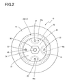
- FIG. 2 is a top view of the bound stopper assembly shown in FIG. 1 ;
- FIG. 3 is an axial cross sectional view of a bracket included in the bound stopper assembly shown in FIG. 1 ;
- FIG. 4 is a top plan view of a bound stopper included in the bound stopper assembly shown in FIG. 1 ;
- FIG. 5 is a cross sectional view taken along line V-V of FIG. 4 ;
- FIG. 6 is a cross sectional view taken along line VI-VI of FIG. 4 .
- the bound stopper assembly of the present embodiment includes a bracket 10 and a bound stopper 12 that are assembled to each other and integrally fixed together.
- a side of the bracket 10 opposite to a side thereof facing the bound stopper 12 and a side of the bound stopper 12 fixed to the bracket 10 are each referred to as “upper” or “upward”, whereas a side opposite thereto is referred to as “lower” or “downward”.
- the bracket 10 included in the bound stopper assembly is comprised of a metal fitting that integrally has a tubular portion 14 and a lower bottom portion 16 and that, as a whole, has a cylindrical shape having a bottom portion at one side and being open upward.
- the tubular portion 14 of the bracket 10 has a tapered tubular shape having a diameter gradually increasing upward.
- the flange portion 18 is projected by a predetermined length outwardly in a radial direction thereof and is continuously extended in a circumferential direction thereof.
- the lower bottom portion 16 of the bracket 10 formed as above, as a whole, has a disc shape and is integrated with the tubular portion 14 having the tapered tubular shape so as to close a lower opening portion of the tubular portion 14 having a small diameter.
- a circular-shaped bolt insertion hole 20 that passes therethrough is formed.
- a total of four circular drainage holes 22 having a smaller diameter than that of the bolt insertion hole 20 is individually formed.
- Each of the circular drainage holes 22 is provided on a peripheral portion of the lower bottom portion so as to have a circumferential regular interval, which is an angular interval of 90 degrees, and the drainage holes 22 pass through the lower bottom portion 16 in its plate thickness direction.
- the bound stopper 12 includes a fixing metal fitting 24 and a stopper body 26 .
- the fixing metal fitting 24 integrally has a tubular portion 28 having a low cylindrical shape and a disc-shaped upper bottom portion 30 with a diameter approximately equal to that of the lower bottom portion 16 of the bracket 10 .
- the fixing metal fitting 24 as a whole has a cylindrical shape having a height lower than that of the bracket 10 and having a bottom at an end thereof or a dished shape with a shallow bottom, which opens downward.
- a lower outer flange portion 32 having a annular plate shape is integrally provided, which is projected by a predetermined length outwardly in a radial direction thereof and continuously extended in a circumferential direction thereof. Furthermore, at a center portion of the upper bottom portion 30 of the fixing metal fitting 24 , a mounting bolt 34 is inserted into a through-hole passing through the center portion of the upper bottom portion 30 and a male screw-threaded leg portion thereof is projected upward from an outer surface (an upper surface) of the upper bottom portion 30 , so that the mounting bolt 34 is firmly fixed so as not to move and rotate.
- the stopper body 26 of the bound stopper 12 is made of a known elastic material such as one of various rubbers and polyurethanes.
- the stopper body 26 is composed of generally rounded V-shaped solid block, in which an outer circumferential surface thereof is a tapered tubular surface having a diameter gradually decreasing downwardly and a lower end surface thereof is formed into a convex curved surface comprised of a part of a spherical surface.
- On an outer circumferential surface of the stopper body 26 there are formed a plurality of ring-shaped grooves 36 extending in a circumferential direction thereof and spaced apart from each other by a predetermined distance in a height direction (an axial direction) thereof.
- portions having the ring-shaped grooves 36 therebetween in the height direction of the stopper body 26 are formed as ring-shaped convex portions 38 , 38 , which are spaced apart from each other by a predetermined distance in the height direction and are extended continuously in the circumferential direction.
- An outer circumferential surface and an upper surface of an upper end portion of the stopper body 26 respectively, have shapes corresponding to shapes of an inner circumferential surface of the tubular portion 28 and an inner surface (a lower surface) of the upper bottom portion 30 of the fixing metal fitting 24 .
- the upper end portion of the stopper body 26 is entered into the tubular portion 28 of the fixing metal fitting 24 , and the outer circumferential surface and the upper surface of the upper end portion are vulcanized and bonded to the inner circumferential surface of the tubular portion 28 and an inner surface of the upper bottom portion 30 of the fixing metal fitting 24 .
- the bound stopper 12 is formed as an integrally vulcanized molded product comprised of the stopper body 26 and the fixing metal fitting 24 .
- each three recessed portions 40 a , 40 b and 40 c which are equally spaced from each other by an angular interval of 90 degrees are provided on an outer circumferential portion of the upper bottom portion 30 of the fixing metal fitting 24 in the bound stopper 12 .
- the each three recessed portions 40 a , 40 b and 40 c have the same shapes and sizes, and a bottom surface 42 of each recessed portion 40 a , 40 b and 40 c is a flat surface flush with an upper surface of the lower outer flange portion 32 of the fixing metal fitting 24 .
- an inner circumferential surface 44 of each three recessed portions is a recessed curved surface forming a substantially semicircular arc.
- each recessed portion 40 a , 40 b and 40 c is formed to be open upward on the outer surface (the upper surface) of the upper bottom portion 30 and to be open outward in the radial direction on the outer circumferential surface of the tubular portion 28 .
- three outer circumferential-surface portions which are spaced from each other by an angular interval of 90 degrees on the outer circumferential surface of the cylindrical tubular portion 28 of the fixing metal fitting 24 are formed as the recessed curved surfaces, which are recessed inward in the radial direction so as to form semicircles having the same diameter.
- the outer circumferential-surface portions comprised of the three recessed curved surfaces form the individual inner circumferential surfaces 44 of the three recessed portions 40 a , 40 b and 40 c .
- three upper surface portions continued to the three recessed curved surfaces are formed as flat surfaces flush with the upper surface of the lower outer flange portion 32 .
- the upper surface portions comprised of the three flat surfaces form the individual bottom surfaces 42 of the three recessed portions 40 a , 40 b and 40 c .
- respective distances indicated by w in FIG.
- the bottom surface 42 of each of the recessed portions 40 a , 40 b and 40 c is the flat surface flush with the upper surface of the lower outer flange portion 32 , whereby a depth size (a size indicated by d in FIG. 6 ) of the recessed portion 40 a , 40 b and 40 c is made equal to a height size of the tubular portion 28 of the fixing metal fitting 24 , namely, is made equal to a height size or an axial-direction length size (a size indicated by h in FIG. 6 ) of the upper end portion of the stopper body 26 entered into the tubular portion 28 . Additionally, a distance (a size indicated by m in FIG.
- a minimum value of distance between the inner circumferential surface 44 of each recessed portion and the center of the fixing metal fitting 24 is made smaller by a predetermined size than a distance (a size indicated by n in FIG. 3 ) between a center of each drainage hole 22 provided in the bracket 10 and a center of the bracket 10 .
- a pin insertion hole 46 is drilled in a portion of the upper bottom portion 30 located on the radially opposite side of the recessed portion 40 b , which is positioned in the middle of the three recessed portions 40 a , 40 b and 40 c , with the center of the fixing metal fitting 24 therebetween, in other words, in the portion of the upper bottom portion 30 which are equally spaced from each other by an angular interval of 90 degrees with respect to the two recessed portions 40 a and 40 c positioned on the opposite adjacent sides of the middle recessed portion 40 b .
- a locating pin 48 as a locating projection is inserted into and fixed to the pin insertion hole 46 .
- the locating pin 48 has a generally T shape integrally having a leg portion with an outer diameter insertable into the drainage hole 22 formed in the lower bottom portion 16 of the bracket 10 and a head portion with a diameter larger than that of the leg portion.
- a distance (a size indicated by s in FIG. 4 ) between a center of the locating pin 48 and the center of the fixing metal fitting 24 (the center of the mounting bolt 34 ) is made equal to the distance (the size indicated by n in FIG. 3 ) between the center of the drainage hole 22 provided in the bracket 10 and the center of the bracket 10 .
- the mounting bolt 34 vertically arranged at the center portion of the upper bottom portion 30 of the fixing metal fitting 24 in the bound stopper 12 is inserted into the bolt insertion hole 20 provided in the center portion of the lower bottom portion 16 of the bracket 10 .
- the locating pin 48 vertically arranged on the outer circumferential portion of the upper bottom portion 30 of the fixing metal fitting 24 is inserted into one of the four drainage holes 22 formed in the outer circumferential portion of the lower bottom portion 16 of the bracket 10 . Consequently, the lower surface of the lower bottom portion 16 of the bracket 10 is superimposed on the upper surface of the upper bottom portion 30 of the bound stopper 12 such that both surfaces are in contact with each other.
- the locating pin 48 is positioned so as to equally space from each other by an angular interval of 90 degrees with respect to the two recessed portions 40 a and 40 c among the three recessed portions 40 a , 40 b and 40 c on the upper bottom portion 30 of the fixing metal fitting 24 in the bound stopper 12 . Additionally, the locating pin 48 is located on the radially opposite side of the remaining single recessed portion 40 b with the center of the fixing metal fitting 24 therebetween.
- the mounting bolt 34 and the locating pin 48 are inserted through or inserted into the bolt insertion hole 20 of the bracket 10 and one of the drainage holes 22 , respectively, and whereby the lower bottom portion 16 of the bracket 10 and the upper bottom portion 30 of the bound stopper 12 are superimposed together so as to be in contact with each other.
- the bound stopper 12 in the above superimposed state (the contacted state) is circumferentially positioned such that each of the three recessed portions 40 a , 40 b and 40 c corresponds to each of three of the four drainage holes 22 , except for the one for inserting the locating pin 48 .
- each one of the three recessed portions 40 a , 40 b and 40 c is provided on each of three corresponding portions of the upper bottom portion 30 of the fixing metal fitting 24 , which are positioned so as to correspond to the three of the four drainage holes 22 .
- Each of the recessed portions 40 a , 40 b and 40 c communicates with each of the three drainage holes 22 and opens outward in the radial direction of the fixing metal fitting 24 (an axial perpendicular direction of the bound stopper 12 ).
- the bracket 10 is fixed onto a lower surface of a vehicle body frame 52 (indicated by a two-dotted chain line in FIG. 1 ), for example, by welding, fixing with a bolt, or the like. Additionally, in the state of being mounted on the vehicle body frame 52 , the bracket 10 is inserted into an inside of a coil spring 54 (indicated by two-dotted chain lines in FIG. 1 ) interposed between the vehicle body frame 52 and a lower arm (not shown in the drawing) supporting wheels. At the same time, a lower surface of the upper outer flange portion 18 of the bracket 10 is in contact with an upper end portion of the coil spring 54 .
- the lower arm comes into contact with a tip surface of the stopper body 26 of the bound stopper 12 when the coil spring 54 is excessively compressed and thereby the not-shown lower arm is excessively displaced upwardly.
- the stopper body 26 is elastically compressed and deformed in its height direction, whereby the upward displacement of the lower arm can be elastically limited.
- the upper end of the stopper body 26 entered into the tubular portion 28 of the fixing metal fitting 24 is vulcanized and bonded to the inner circumferential surface of the tubular portion 28 and the inner surface (the lower surface) of the upper bottom portion 30 .
- the stopper body 26 is more securely held by the fixing metal fitting 24 , so that the stopper body 26 can be efficiently compressed and deformed when abutted with the lower arm.
- sufficient vibration damping characteristics can be advantageously exhibited when the lower arm is excessively displaced.
- the stopper body 26 is composed of the solid block, whereby the stopper body 26 can be efficiently compressed and deformed when abutted with the lower arm as compared with the stopper body 26 composed of a hollow body such as a cylindrical body, for example.
- the stopper body 26 composed of a hollow body such as a cylindrical body, for example.
- the stopper body 26 has the ring-shaped convex portions 38 located apart from each other by the predetermined distance in the height direction with the ring-shaped grooves 36 arranged therebetween.
- the drainage paths for draining water in the tubular portion 14 of the bracket 10 through the drainage holes 22 are formed only by the recessed portions 40 a , 40 b and 40 c provided in the fixing metal fitting 24 of the bound stopper 12 , and no drainage path is formed in the stopper body 26 .
- the bound stopper 12 including the integrally vulcanized molded product composed of the fixing metal fitting 24 and the stopper body 26
- employment of the fixing metal fitting 24 with the preliminarily molded recessed portions 40 a , 40 b and 40 c makes it possible to use a simply designed mold as a mold for integrally vulcanizing and molding the fixing metal fitting 24 and the stopper body 26 , without any need for using a slide-type mold or a mold with a pin or the like necessary to form a groove or a hole as a part of the drainage path in the stopper body 26 . Accordingly, the bound stopper 12 , and furthermore, the bound stopper assembly can be advantageously produced through a simple operation at a maximally reduced cost.
- the locating pin 48 formed on the fixing metal fitting 24 of the bound stopper 12 is inserted into one of the four drainage holes 22 provided in the bracket 10 .
- the circumferential position of the bound stopper 12 upon the bound stopper 12 being in contact (superimposed) with the bracket 10 , is determined simply by the insertion of the pin into the hole such that each of the three recessed portions 40 a , 40 b and 40 c corresponds to each of the three drainage holes 22 , thereby forming the drainage paths.
- the bound stopper 12 is formed by the integrally vulcanized molded product comprised of the fixing metal fitting 24 and the stopper body 26 , whereby sufficient vibration damping characteristics can be ensured in the small structure, and also a structure for draining water that has entered the bracket 10 can be very advantageously obtained with the simple and low-cost structure.
- efficiency of a mounting operation of the bound stopper 12 , and furthermore, the bound stopper assembly onto the vehicle body frame 52 can be advantageously improved.
- use durability of the assembly in the state of being mounted on the vehicle body frame 52 can also be effectively improved.
- the stopper body 26 is composed of the solid block, and the depth size d of each of the recessed portions 40 a , 40 b and 40 c is made equal to the height size h of the upper end portion of the stopper body 26 entered into the tubular portion 28 of the fixing metal fitting 24 .
- a rubber portion excluded from the stopper body 26 as a portion to be elastically deformed is restricted to a part of the upper end portion of the stopper body 26 entered into the tubular portion 28 thereof, in other words, to a part of the upper end portion thereof that is substantially not compressed or deformed because the volume thereof cannot be changed when the stopper body 26 is under elastic compression and deformation.
- the forgoing embodiment can advantageously exhibit the above especially outstanding function and effect, that is, the improved efficiency of mounting operation of the bound stopper 12 , and furthermore, of the bound stopper assembly onto the vehicle body frame 52 , and also the improved use-durability thereof in the state of being mounted on the vehicle body frame 52 .
- the drainage holes 22 are provided one by one at the positions where the drainage holes 22 are equally spaced from each other by an angular interval of 90 degrees, namely, at each of the positions where they are spaced apart from each other by an equal distance in the circumferential direction.
- the single locating pin 48 and the three recessed portions 40 a , 40 b and 40 c are provided at the positions where they are equally spaced from each other by an angular interval of 90 degrees on the outer circumferential portion of the upper bottom portion 30 of the fixing metal fitting 24 thereof, namely, at the positions where they are spaced apart from each other by the equal distance in the circumferential direction.
- the insertion of the locating pin 48 into any one of them allows the bracket 10 to come into contact with the bound stopper 12 , thereby positioning the bound stopper 12 easily and surely such that each of the three recessed portions 40 a , 40 b and 40 c corresponds to each of the three drainage holes 22 upon the bound stopper 12 being in contact with the bracket 10 . Consequently, the drainage path for draining water in the bracket 10 through each of the drainage holes 22 can be more easily formed.
- the numbers of the recessed portion 40 a , 40 b and 40 c and of the locating pin 48 as the locating projection, which are provided on the upper bottom portion 30 of the fixing metal fitting 24 in the bound stopper 12 are not particularly limited to that of the illustrated embodiment.
- the numbers thereof may be at least one.
- the number of the drainage hole 22 formed in the lower bottom portion 16 of the bracket 10 may also be appropriately changed depending upon the numbers of the recessed portion 40 a , 40 b and 40 c and of the locating pin 48 .
- the formation positions of the recessed portions 40 a , 40 b and 40 c and of the locating pin 48 on the upper bottom portion 30 of the fixing metal fitting 24 of the bound stopper 12 , and the positions of the drainage holes 22 on the lower bottom portion 16 of the bracket 10 are also not limited as long as the recessed portions 40 a , 40 b and 40 c and the locating pin 48 are located so as to correspond to the drainage holes 22 in the state where the upper bottom portion 30 of the fixing metal fitting 24 in the bound stopper 12 is in contact with the lower bottom portion 16 of the bracket 10 .
- the locating pin 48 as the locating projection may be vertically arranged on any of an inner bottom surface of the recessed portions 40 a , 40 b and 40 c , namely, on the bottom surface 42 of any of the recessed portions 40 a , 40 b and 40 c.
- the depth size d of each of the recessed portions 40 a , 40 b and 40 c is made equal to the height size h of the upper end portion of the stopper body 26 entered into the tubular portion 28 of the fixing metal fitting 24 .
- the relationship between the depth size d of the recessed portions 40 a , 40 b and 40 c and the height size h of the upper end portion of the stopper body 26 is not strictly limited.
- the depth size d of each recessed portion 40 a , 40 b and 40 c is equal to or smaller than the height size h of the upper end portion of the stopper body 26 entered into the tubular portion 28 of the fixing metal fitting 24 , in other words, the height size of the tubular portion 28 of the fixing metal fitting 24 .
- the entire shape of the bracket 10 , the entire shapes of the fixing metal fitting 24 and the stopper body 26 of the bound stopper 12 are also not particularly limited to the illustrated embodiment.
- the present invention may also be advantageously applied to any bound stopper and any bound stopper assembly to be mounted on vehicle bodies other than automobile bodies, and to any bound stopper mounting structure for vehicle bodies other than automobile bodies.
Landscapes
- Engineering & Computer Science (AREA)
- Mechanical Engineering (AREA)
- Vehicle Body Suspensions (AREA)
- Springs (AREA)
Abstract
Description
Claims (15)
Applications Claiming Priority (2)
| Application Number | Priority Date | Filing Date | Title |
|---|---|---|---|
| JP2007045219A JP4914741B2 (en) | 2007-02-26 | 2007-02-26 | Bound stopper, bound stopper assembly, and bound stopper mounting structure for vehicle body |
| JP2007-045219 | 2007-02-26 |
Publications (2)
| Publication Number | Publication Date |
|---|---|
| US20080203764A1 US20080203764A1 (en) | 2008-08-28 |
| US7793922B2 true US7793922B2 (en) | 2010-09-14 |
Family
ID=39715033
Family Applications (1)
| Application Number | Title | Priority Date | Filing Date |
|---|---|---|---|
| US12/027,281 Active 2029-03-13 US7793922B2 (en) | 2007-02-26 | 2008-02-07 | Bound stopper, bound stopper assembly, and bound stopper mounting structure for vehicle body |
Country Status (2)
| Country | Link |
|---|---|
| US (1) | US7793922B2 (en) |
| JP (1) | JP4914741B2 (en) |
Cited By (5)
| Publication number | Priority date | Publication date | Assignee | Title |
|---|---|---|---|---|
| US20090127043A1 (en) * | 2007-11-21 | 2009-05-21 | Dickson Daniel G | Insulator for vehicle suspension system |
| US20090127759A1 (en) * | 2007-11-21 | 2009-05-21 | Basf Corporation | Insulator for a vehicle suspension system |
| US10000102B2 (en) * | 2015-06-19 | 2018-06-19 | GM Global Technology Operations LLC | Tunable compact spring aid |
| US10274036B2 (en) * | 2015-11-24 | 2019-04-30 | Basf Se | Energy management jounce bumper assembly |
| US11236791B2 (en) * | 2019-10-18 | 2022-02-01 | Raytheon Company | Multi-axial energy damping and displacement control |
Families Citing this family (5)
| Publication number | Priority date | Publication date | Assignee | Title |
|---|---|---|---|---|
| JP5714363B2 (en) * | 2011-03-10 | 2015-05-07 | 東洋ゴム工業株式会社 | Anti-vibration connecting rod |
| FR2996615B1 (en) * | 2012-10-05 | 2017-02-10 | Peugeot Citroen Automobiles Sa | ATTACKING FASTER FOR THE SUSPENSION OF A VEHICLE, COMPRISING A FIRST LINEAR STIFFNESS WITHOUT HYSTERESIS |
| CN106402232B (en) * | 2016-10-12 | 2018-02-13 | 山东国金汽车工程技术有限公司 | A kind of pagoda-shaped rear overhang upper limit position block |
| DE102017203610B4 (en) * | 2017-03-06 | 2020-09-10 | Engineering Center Steyr Gmbh & Co. Kg | End stop buffer as well as commercial vehicle with end stop buffer |
| KR102062876B1 (en) * | 2018-04-13 | 2020-01-06 | 이상욱 | coil spring support for an automobile rear suspension |
Citations (11)
| Publication number | Priority date | Publication date | Assignee | Title |
|---|---|---|---|---|
| US2732903A (en) * | 1956-01-31 | chayne | ||
| US5211380A (en) * | 1991-02-27 | 1993-05-18 | Dr. Ing. H.C.F. Porsche Ag | Motor vehicle spring strut |
| JPH0586048U (en) | 1992-04-24 | 1993-11-19 | 豊田合成株式会社 | Bound stopper for automobile |
| US5308048A (en) * | 1993-09-30 | 1994-05-03 | Chrysler Corporation | Front suspension strut upper mount |
| US5419539A (en) * | 1993-08-16 | 1995-05-30 | Freudenberg-Nok General Partnership | Elastomeric shock absorber with positioning insert |
| JPH09272317A (en) | 1996-04-10 | 1997-10-21 | Shinko Seisakusho:Kk | Bump stopper |
| JPH09300931A (en) | 1996-05-20 | 1997-11-25 | Toyo Tire & Rubber Co Ltd | Bound stopper for vehicle |
| US6158726A (en) * | 1998-05-11 | 2000-12-12 | Freudenberg Nok-General Partnership | Integrated cup insert jounce bumper |
| JP2004225799A (en) | 2003-01-22 | 2004-08-12 | Tokai Rubber Ind Ltd | Bound stopper for vehicle |
| US20060151928A1 (en) * | 2005-01-12 | 2006-07-13 | Toyo Tire & Rubber Co., Ltd. | Strut mount |
| JP2006248401A (en) | 2005-03-11 | 2006-09-21 | Tokai Rubber Ind Ltd | Elastic connecting device for shock absorber |
Family Cites Families (3)
| Publication number | Priority date | Publication date | Assignee | Title |
|---|---|---|---|---|
| JPH07107003B2 (en) * | 1986-10-16 | 1995-11-15 | 三菱瓦斯化学株式会社 | Method for producing 2,3,5-trimethylhydroquinone |
| JP2005016641A (en) * | 2003-06-26 | 2005-01-20 | Tokai Rubber Ind Ltd | Dust cover |
| US20060244188A1 (en) * | 2005-04-28 | 2006-11-02 | Johnson Lawrence W | Body mount assembly |
-
2007
- 2007-02-26 JP JP2007045219A patent/JP4914741B2/en active Active
-
2008
- 2008-02-07 US US12/027,281 patent/US7793922B2/en active Active
Patent Citations (11)
| Publication number | Priority date | Publication date | Assignee | Title |
|---|---|---|---|---|
| US2732903A (en) * | 1956-01-31 | chayne | ||
| US5211380A (en) * | 1991-02-27 | 1993-05-18 | Dr. Ing. H.C.F. Porsche Ag | Motor vehicle spring strut |
| JPH0586048U (en) | 1992-04-24 | 1993-11-19 | 豊田合成株式会社 | Bound stopper for automobile |
| US5419539A (en) * | 1993-08-16 | 1995-05-30 | Freudenberg-Nok General Partnership | Elastomeric shock absorber with positioning insert |
| US5308048A (en) * | 1993-09-30 | 1994-05-03 | Chrysler Corporation | Front suspension strut upper mount |
| JPH09272317A (en) | 1996-04-10 | 1997-10-21 | Shinko Seisakusho:Kk | Bump stopper |
| JPH09300931A (en) | 1996-05-20 | 1997-11-25 | Toyo Tire & Rubber Co Ltd | Bound stopper for vehicle |
| US6158726A (en) * | 1998-05-11 | 2000-12-12 | Freudenberg Nok-General Partnership | Integrated cup insert jounce bumper |
| JP2004225799A (en) | 2003-01-22 | 2004-08-12 | Tokai Rubber Ind Ltd | Bound stopper for vehicle |
| US20060151928A1 (en) * | 2005-01-12 | 2006-07-13 | Toyo Tire & Rubber Co., Ltd. | Strut mount |
| JP2006248401A (en) | 2005-03-11 | 2006-09-21 | Tokai Rubber Ind Ltd | Elastic connecting device for shock absorber |
Cited By (6)
| Publication number | Priority date | Publication date | Assignee | Title |
|---|---|---|---|---|
| US20090127043A1 (en) * | 2007-11-21 | 2009-05-21 | Dickson Daniel G | Insulator for vehicle suspension system |
| US20090127759A1 (en) * | 2007-11-21 | 2009-05-21 | Basf Corporation | Insulator for a vehicle suspension system |
| US8276894B2 (en) * | 2007-11-21 | 2012-10-02 | Basf Corporation | Insulator for a vehicle suspension system |
| US10000102B2 (en) * | 2015-06-19 | 2018-06-19 | GM Global Technology Operations LLC | Tunable compact spring aid |
| US10274036B2 (en) * | 2015-11-24 | 2019-04-30 | Basf Se | Energy management jounce bumper assembly |
| US11236791B2 (en) * | 2019-10-18 | 2022-02-01 | Raytheon Company | Multi-axial energy damping and displacement control |
Also Published As
| Publication number | Publication date |
|---|---|
| JP2008207649A (en) | 2008-09-11 |
| US20080203764A1 (en) | 2008-08-28 |
| JP4914741B2 (en) | 2012-04-11 |
Similar Documents
| Publication | Publication Date | Title |
|---|---|---|
| US7793922B2 (en) | Bound stopper, bound stopper assembly, and bound stopper mounting structure for vehicle body | |
| KR101982687B1 (en) | Top mount assembly and method of manufacturing same | |
| US7350777B2 (en) | Engine mount | |
| US8181945B2 (en) | Cylindrical vibration isolating device | |
| US7052002B2 (en) | Vibration-damping device | |
| JP2008024158A (en) | Positioning structure of coil spring | |
| JP2005520099A (en) | Fitting | |
| US5163769A (en) | Ball joint having service life indicator | |
| JP3937042B2 (en) | Strut mount | |
| US6394436B1 (en) | Suspension-strut bearing | |
| US20060225785A1 (en) | Sealing structure of float valve | |
| EP1270991B1 (en) | Vibration isolating device | |
| JP2006090409A (en) | Vibration isolation bushing | |
| US20190322320A1 (en) | Body Mount | |
| JP2007010005A (en) | Strut mount and its manufacturing method | |
| US6457703B1 (en) | Engine mount | |
| JP3767364B2 (en) | Spring seat for vehicle suspension | |
| JP4314023B2 (en) | Spring support bearing | |
| US20050053420A1 (en) | Ball joint seal for a ball joint assembly | |
| JP2008038965A (en) | Hollow spring | |
| JP4664172B2 (en) | bush | |
| JP3988068B2 (en) | bush | |
| JP2006264425A (en) | Upper support for suspension, and suspension device for automobile using the same | |
| JP6381221B2 (en) | Buffer member | |
| JP2002323078A (en) | Seat spring rubber |
Legal Events
| Date | Code | Title | Description |
|---|---|---|---|
| AS | Assignment |
Owner name: TOKAI RUBBER INDUSTRIES, LTD., JAPAN Free format text: ASSIGNMENT OF ASSIGNORS INTEREST;ASSIGNORS:HIKOSAKA, MICHIHARU;FUKUMOTO, YASUTAKA;HISHINUMA, TAKUYA;AND OTHERS;REEL/FRAME:020473/0614 Effective date: 20080204 Owner name: TOKAI RUBBER INDUSTRIES, LTD.,JAPAN Free format text: ASSIGNMENT OF ASSIGNORS INTEREST;ASSIGNORS:HIKOSAKA, MICHIHARU;FUKUMOTO, YASUTAKA;HISHINUMA, TAKUYA;AND OTHERS;REEL/FRAME:020473/0614 Effective date: 20080204 |
|
| STCF | Information on status: patent grant |
Free format text: PATENTED CASE |
|
| FEPP | Fee payment procedure |
Free format text: PAYOR NUMBER ASSIGNED (ORIGINAL EVENT CODE: ASPN); ENTITY STATUS OF PATENT OWNER: LARGE ENTITY |
|
| FPAY | Fee payment |
Year of fee payment: 4 |
|
| AS | Assignment |
Owner name: SUMITOMO RIKO COMPANY LIMITED, JAPAN Free format text: CHANGE OF NAME;ASSIGNOR:TOKAI RUBBER INDUSTRIES, LTD.;REEL/FRAME:034016/0613 Effective date: 20141001 |
|
| MAFP | Maintenance fee payment |
Free format text: PAYMENT OF MAINTENANCE FEE, 8TH YEAR, LARGE ENTITY (ORIGINAL EVENT CODE: M1552) Year of fee payment: 8 |
|
| MAFP | Maintenance fee payment |
Free format text: PAYMENT OF MAINTENANCE FEE, 12TH YEAR, LARGE ENTITY (ORIGINAL EVENT CODE: M1553); ENTITY STATUS OF PATENT OWNER: LARGE ENTITY Year of fee payment: 12 |