US7791240B2 - Stir-welded rotors and methods of making - Google Patents
Stir-welded rotors and methods of making Download PDFInfo
- Publication number
- US7791240B2 US7791240B2 US11/829,270 US82927007A US7791240B2 US 7791240 B2 US7791240 B2 US 7791240B2 US 82927007 A US82927007 A US 82927007A US 7791240 B2 US7791240 B2 US 7791240B2
- Authority
- US
- United States
- Prior art keywords
- stir
- ring
- laminations
- slot bars
- rotor
- Prior art date
- Legal status (The legal status is an assumption and is not a legal conclusion. Google has not performed a legal analysis and makes no representation as to the accuracy of the status listed.)
- Expired - Fee Related, expires
Links
Images


Classifications
-
- H—ELECTRICITY
- H02—GENERATION; CONVERSION OR DISTRIBUTION OF ELECTRIC POWER
- H02K—DYNAMO-ELECTRIC MACHINES
- H02K15/00—Processes or apparatus specially adapted for manufacturing, assembling, maintaining or repairing of dynamo-electric machines
- H02K15/02—Processes or apparatus specially adapted for manufacturing, assembling, maintaining or repairing of dynamo-electric machines of stator or rotor bodies
- H02K15/021—Magnetic cores
-
- Y—GENERAL TAGGING OF NEW TECHNOLOGICAL DEVELOPMENTS; GENERAL TAGGING OF CROSS-SECTIONAL TECHNOLOGIES SPANNING OVER SEVERAL SECTIONS OF THE IPC; TECHNICAL SUBJECTS COVERED BY FORMER USPC CROSS-REFERENCE ART COLLECTIONS [XRACs] AND DIGESTS
- Y10—TECHNICAL SUBJECTS COVERED BY FORMER USPC
- Y10T—TECHNICAL SUBJECTS COVERED BY FORMER US CLASSIFICATION
- Y10T29/00—Metal working
- Y10T29/49—Method of mechanical manufacture
- Y10T29/49002—Electrical device making
- Y10T29/49009—Dynamoelectric machine
- Y10T29/49012—Rotor
-
- Y—GENERAL TAGGING OF NEW TECHNOLOGICAL DEVELOPMENTS; GENERAL TAGGING OF CROSS-SECTIONAL TECHNOLOGIES SPANNING OVER SEVERAL SECTIONS OF THE IPC; TECHNICAL SUBJECTS COVERED BY FORMER USPC CROSS-REFERENCE ART COLLECTIONS [XRACs] AND DIGESTS
- Y10—TECHNICAL SUBJECTS COVERED BY FORMER USPC
- Y10T—TECHNICAL SUBJECTS COVERED BY FORMER US CLASSIFICATION
- Y10T428/00—Stock material or miscellaneous articles
- Y10T428/12—All metal or with adjacent metals
- Y10T428/12229—Intermediate article [e.g., blank, etc.]
- Y10T428/12236—Panel having nonrectangular perimeter
- Y10T428/1225—Symmetrical
Definitions
- the embodiments described herein generally relate to electrical motors, and more particularly relate to stir-welded rotors for electric motors.
- a typical induction motor includes at a minimum a central rotor surrounded by a stator.
- the stator includes windings through which an electrical current flows to produce a magnetic field.
- the magnetic field interacts with the rotor thereby causing the rotor to rotate.
- Induction motors are relatively efficient in converting electrical energy into mechanical energy and as a result there is an increasing interest in such motors in a variety of applications, including in the automotive field.
- Induction motors may, for example, find increasing application in hybrid powered vehicles that use a combination of an internal combustion engine and one or more electric motors to provide motive power.
- Electrical induction motors find application in other areas as well as providing supplemental motive power.
- induction motors may provide power to a range of accessories that might otherwise be powered via hydraulic or other systems that are driven by an internal combustion engine.
- induction motors that conform to desired design parameters such as vehicle total mass, vehicle mass distribution, vehicle packaging that imposes space limitations, and cost and ease of mass production.
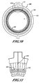
- FIGS. 1-2 illustrate an example of three stages of making a typical rotor 10 .
- the final rotor 10 shown in FIG. 1 includes a stacked series of consolidated steel laminations 40 , seen more clearly in FIG. 2 in pre-consolidated form.
- FIG. 2 illustrates circular steel laminations 20 arrayed in a vertical stack 30 . These laminations each have a central circular hole 24 and each lamination has a perimeter that includes a series of slots 22 .
- these laminations 20 are stacked and are then consolidated by die casting, while also forming a lower end ring 32 and an upper end ring 38 , as shown in FIG.
- molten aluminum flows between the slots 22 of the stacked laminations to consolidate the laminations 20 and also to form the upper end ring 38 and lower end ring 32 , shown in FIG. 1 , after appropriate post-casting machining.
- An exemplary embodiment of a stir-welded rotor may include a stack of laminations that each has spaced-apart slots arrayed on an outer circumference.
- the slots register with slot bars that each has a first extremity extending above the stack of laminations and a second extremity extending below the stack of laminations.
- a first weld extends between first extremities of adjacent slot bars, and a second stir weld extends between second extremities of adjacent slot bars.
- a stir-welded rotor may have a first and a second end ring.
- a stack of laminations is interposed between the first end ring and the second end ring.
- Each of the laminations has spaced-apart slots arrayed on an outer circumference and slot bars register with the spaced-apart slots.
- the slot bars have first extremities and second extremities.
- a first stir weld extends between first extremities of the slot bars and a second stir weld extends between second extremities of the slot bars.
- An exemplary embodiment of a method of making stir-welded rotors may include, in any sequence, the following steps. Stacking laminations that each has spaced-apart slots on their respective outer circumference. Registering each of the spaced-apart slots with a corresponding slot bar of an array of slot bars, where each slot bar has a first extremity and a second extremity. In addition, restraining reciprocal and rotational movement of the stacked laminations, and stir welding first extremities of the slot bars to form a substantially continuous circular stir weld.
- FIG. 1 is an illustration of a prior art induction motor rotor
- FIG. 2 is an illustration of a stack of laminations of the prior art used to make an induction motor rotor
- FIG. 3 is a perspective view of an exemplary embodiment of a rotor assembly being assembled and illustrates stacking of laminations onto an end ring with vertical slot bars in place;
- FIG. 4 is a perspective view of an exemplary embodiment of a rotor assembly including an outer assembly ring and an inner assembly ring;
- FIG. 5 is a top view of the embodiment of FIG. 4 ;
- FIG. 6 is a cross-sectional view along 6-6 of FIG. 5 ;
- FIG. 7 is a portion of a cross-sectional view illustrating an example of a stir weld zone
- FIG. 8 is a cross-sectional view of an example of a stir-welded rotor that is ready for stamping
- FIG. 9 is a cross-sectional view of an example of a stir-welded rotor that is ready to be machined axially and radially;
- FIG. 10 is a top view of another exemplary embodiment of a rotor assembly including an outer assembly ring and an inner assembly ring;
- FIG. 11 is an enlarged view of a portion of the embodiment of FIG. 10 to show detail
- FIGS. 12-15 depict an exemplary embodiment in various stages of production, in cross section
- FIG. 16 is an example of an embodiment of a method of making stir-welded rotors.
- FIG. 17 is another example of an embodiment of a method of making stir-welded rotors.
- the term “inboard” as used herein refers to a position relative to a point of reference (or component of the rotor) and indicates a position closer to an axial center line of the rotor than the point of reference.
- the term “outboard” conversely refers to a position further from an axial centerline of the rotor than the point of reference (or component of the rotor).
- Exemplary embodiments provide the potential of using manufacturing processes that are less costly alternatives to die casting, that enable the use of a wider variety of alloys, and that provide rotors with tight tolerances. Construction methods may reduce the need or extent of subsequent machining of a rotor relative to a die cast rotor. Further, exemplary embodiments may have little or no porosity issues that cause degradation of strength and electrical properties.
- laminations may be made of steel while slot bars may be of any material with good electrical conductivity and adequate strength, such as aluminum 6101-T6 or copper.
- the end rings may be of the same material as the slot bars or may of a different material, for example aluminum 6061-T6.
- FIGS. 3-6 An exemplary embodiment, illustrated in FIGS. 3-6 , shows how the rotor components may be assembled for a stir-weld consolidation process.
- the stir weld assembly 100 includes a series of nested components.
- the stir weld assembly 100 includes an outer assembly ring 110 and an inner assembly ring 120 .
- the inner assembly ring 120 and the outer assembly ring 110 provide support for the rotor components during the stir weld process.
- the stir weld assembly 100 includes a stack of flat plate-like laminations 130 ( FIG. 6 ) with central holes 135 abutting the inner assembly ring 120 and outside diameters supported against the outer assembly ring 110 .
- the laminations 130 have regularly-spaced slots 132 on their outer circumferences each of which registers with a vertical slot bar 134 , as shown in FIG. 3 .
- Each slot bar 134 is supported in a vertical orientation on a lower separator plate 142 .
- the slot bars may be at least partially wrapped in a thin electrically insulating material, such as NOMEX® (Trademark of DuPont of Wilmington, Del.) to provide a barrier between the slot bar 134 and laminations 130 to improve the electrical performance of the rotor.
- An inner assembly ring 120 abuts against the central holes 135 of the laminations 130 as stacked, as shown in FIG. 6 , for example.
- a lower outer end ring 144 with vertical grooves (not shown) that register with the lower ends 138 of the slot bars 134 extends around the outside of the array of slot bars 134 .
- a lower inner end ring 165 with vertical grooves (not shown) that register with the lower ends 138 of the slot bars 134 is interposed between lower ends 138 of slot bars 134 and the inner assembly ring 120 .
- lower outer end ring 144 and lower inner end ring 165 together surround the a portion of the vertical lower ends 138 of slot bars 134 .
- an upper inner end ring 160 with vertical grooves that register with upper ends 136 of the slot bars 134 is interposed between upper ends 136 of slot bars 134 and the inner assembly ring 120 .
- an upper outer end ring 150 with vertical grooves that register with upper ends 136 of the slot bars 134 extends around the outside of the array of slot bars 134 .
- upper outer end ring 150 and upper inner end ring 160 together surround a portion of the vertical upper ends 136 of slot bars 134 .
- the slot bars 134 are restrained from rotational and reciprocal motion.
- the laminations 130 are restrained from rotational motion relative to each other by the slot bars 134 that are, in turn, restrained by the end rings 144 , 165 , 150 , 160 .
- a lower weld ring 170 extends around the lower outer end ring 144 and rests upon the lower separator plate 142 .
- Lower weld ring 170 lies beneath an outer end ring 180 that extends upward to an underside of upper weld ring 175 .
- Upper weld ring 175 is held in place between the outer end ring 180 and the surrounding outer assembly ring 110 .
- the outer end ring 180 may be supplied with channels 182 for a supply of a suitable coolant to minimize potential heat effects during stir welding.
- FIG. 5 An example of the area covered by the stir weld tool is shown in FIG. 5 , as circles 200 , 202 .
- FIG. 7 illustrates schematically a stir weld tool 300 and the welding zone 310 beneath the tool.
- the welding zone 310 encompasses the upper weld ring 175 , the upper ends 136 of the slot bars 134 and the upper inner end ring 160 . These components are stir-welded for the entire upper ends 102 and lower ends 104 of the stir weld assembly 100 to produce a substantially continuous stir weld. The stir-welded rotor assembly may then be subjected to machining to remove extraneous material.
- FIG. 8 illustrates an example of a stir-welded rotor 250 .
- the inner assembly ring 120 and outer assembly ring 110 were removed.
- the stir-welded rotor will then be stamped to remove lower weld ring 170 and upper weld ring 175 from upper end 102 and lower end 104 of the stir weld assembly 100 , without affecting the slot bars 134 .
- FIG. 9 illustrates another example of a stir-welded rotor 250 .
- the stir-welded rotor 250 was then axially machined without affecting the slot bars 134 while retaining upper outer end ring 150 and a lower outer end ring 144 at least partially intact.
- the remaining portions of the upper weld ring 175 and lower weld ring 170 may be removed by a radial machining process, if necessary or desired.
- FIGS. 10-11 illustrate a top view and an enlarged view of a portion of the top, respectively, of another embodiment of a stir weld assembly 400 for making stir-welded rotors.
- a stir weld assembly 400 a plurality of flat wedge-shaped stir-weldable metal keys 410 are used to form upper and lower end rings.
- the keys 410 each have cutouts 414 that are sized to receive apportion of a cross section of a slot bar, of which only upper bar ends 136 are shown.
- the cutouts are arrayed on the stir weld assembly 400 , they cover the surface, except for the upper ends 136 of the slot bars (and the inner assembly ring 120 and outer assembly ring 110 , which are both removed after stir welding is complete).
- FIGS. 12-15 illustrate stages in the fabrication of an embodiment that includes keys 410 .
- a flat circular lower separator plate 142 supports a toothed separator plate 143 that has a series of teeth 145 around its perimeter that are sized to register with slots in the laminations 130 and the bars 134 .
- the lower separator plate 142 is configured to engage the central holes 135 of the laminations and the slot bars 134 .
- the slot bars 134 are inserted as shown in FIG. 12 .
- keys 410 are arrayed along the upper end of the assembly around the upper ends of slot bars 134 , as shown in FIGS. 10-11 .
- FIG. 12 keys 410 are arrayed along the upper end of the assembly around the upper ends of slot bars 134 , as shown in FIGS. 10-11 .
- the inner assembly ring 120 is applied and the outer assembly ring 110 is clamped around the assembly.
- the assembly is now in condition for stir welding of the keys 410 to the slot bars 134 .
- the assembly is upended, as shown in FIG. 15 .
- the lower separator plate 142 is removed and placed beneath the assembly, adjacent the welded keys 410 , to act as a support during welding of the other end of the assembly.
- keys 410 are arrayed at the upper end of the assembly, around slot bars 134 , to form a complete coverage of the surface area between the slot bars 134 and an applied inner assembly ring 120 .
- the keys 410 are then stir welded to the upper ends of slot bars 134 slot bars to form a substantially continuous circular stir weld.
- FIG. 16 is an exemplary embodiment of a process 500 for making stir-welded rotors.
- rotor assembly commences with selecting and laying down a separator plate and lower end ring in process 510 .
- An array of spaced-apart vertical slot bars is erected on the lower end ring, in process 515 .
- Laminations are stacked on top of the inner assembly ring and the lower end ring such that each slot of each lamination registers with a corresponding slot bar, in process 520 .
- the weld assembly is prepared in process 530 by adding an upper end ring on top of the stack.
- an inner assembly ring typically a slightly tapered steel cylinder, is fitted into the inner circumference of the end ring.
- the weld ring is applied to hold the assembled components in place during the welding process or to provide more space for the stir weld tool.
- the outer assembly ring is clamped around the assembly in process 550 .
- the assembly is stir welded to weld the slot bars to the end ring to form a substantially continuous circular stir weld
- process 570 the assembly is upended, and the separator plate is removed and applied to the welded end to provide support on the work surface, in process 580 .
- process 590 the top end is now stir welded to weld the end ring to the slot bars to form a substantially continuous circular stir weld.
- the inner and outer assembly rings may be removed in process 600 .
- the manufactured rotor is now in condition for post-weld machining in process 610 .
- Post-stir welding machining may include, for example, axial machining, radial machining and stamping to remove any extraneous material to produce a finished stir-welded rotor.
- the machined and stir-welded rotor product may be subjected to inspection for quality and performance criteria, in process 620 .
- FIG. 17 illustrates a series of processes relating to a rotor that has stir-welded keys.
- a flat, circular, lower separator plate is laid on a work surface and supports a toothed separator plate with teeth around its perimeter that are sized to register with slots in laminations and the slot bars.
- laminations are stacked on the separator plate.
- slot bars are erected 130 .
- the stir weld assembly is prepared. This may include several processes, such as arranging the keys to be welded around the upper ends of the slot bars, in process 745 .
- An inner assembly ring may be installed in process 750 and an outer assembly ring clamped around the assembly in process 760 .
- the clamped assembly is now in condition for stir welding the keys to ends of the slot bars to form a substantially continuous, circular, stir weld, in process 770 .
- the assembly is upended, in process 780 .
- the separator plate is removed in process 785 and applied to the underside of the assembly, adjacent the stir-welded keys, as a support, in process 790 . Keys are arranged on top of the assembly around the exposed upper ends of the slot bars, in process 795 .
- the outer assembly ring may have to be unclamped in order to do this.
- an inner assembly ring is applied in process 800 .
- the keys are stir welded to the slot bars in process 810 to form a substantially continuous, circular, stir weld.
- the inner and outer assembly rings are removed in process 820 .
- Post-stir welding machining of the stir-welded rotor may then be carried out in process 830 .
- Process 830 may include for example, axial machining, radial machining and stamping to remove any extraneous material to produce a finished stir-welded rotor.
- the machined and stir-welded rotor product may be subjected to inspection for quality and performance criteria, in process 840 .
Landscapes
- Engineering & Computer Science (AREA)
- Manufacturing & Machinery (AREA)
- Power Engineering (AREA)
- Manufacture Of Motors, Generators (AREA)
- Induction Machinery (AREA)
Abstract
Description
Claims (8)
Priority Applications (3)
| Application Number | Priority Date | Filing Date | Title |
|---|---|---|---|
| US11/829,270 US7791240B2 (en) | 2007-07-27 | 2007-07-27 | Stir-welded rotors and methods of making |
| DE102008034355A DE102008034355A1 (en) | 2007-07-27 | 2008-07-23 | Stirred rotors and methods of making the same |
| CN2008101443463A CN101399473B (en) | 2007-07-27 | 2008-07-25 | Stir welded rotor and manufacturing method thereof |
Applications Claiming Priority (1)
| Application Number | Priority Date | Filing Date | Title |
|---|---|---|---|
| US11/829,270 US7791240B2 (en) | 2007-07-27 | 2007-07-27 | Stir-welded rotors and methods of making |
Publications (2)
| Publication Number | Publication Date |
|---|---|
| US20090026877A1 US20090026877A1 (en) | 2009-01-29 |
| US7791240B2 true US7791240B2 (en) | 2010-09-07 |
Family
ID=40294658
Family Applications (1)
| Application Number | Title | Priority Date | Filing Date |
|---|---|---|---|
| US11/829,270 Expired - Fee Related US7791240B2 (en) | 2007-07-27 | 2007-07-27 | Stir-welded rotors and methods of making |
Country Status (3)
| Country | Link |
|---|---|
| US (1) | US7791240B2 (en) |
| CN (1) | CN101399473B (en) |
| DE (1) | DE102008034355A1 (en) |
Cited By (5)
| Publication number | Priority date | Publication date | Assignee | Title |
|---|---|---|---|---|
| US20100007234A1 (en) * | 2008-07-09 | 2010-01-14 | Gm Global Technology Operations, Inc. | Squirrel-cage rotors and methods of manufacturing same |
| US20120267978A1 (en) * | 2009-09-09 | 2012-10-25 | Ansaldobreda S.P.A. | Squirrel-cage rotor for asynchronous motors |
| US20130033144A1 (en) * | 2011-08-04 | 2013-02-07 | GM Global Technology Operations LLC | Stir-welded induction rotor |
| US9130434B2 (en) | 2012-02-01 | 2015-09-08 | Remy Technologies, Llc | Induction rotor end ring support device |
| US20160352200A1 (en) * | 2014-02-28 | 2016-12-01 | Nhk Spring Co., Ltd. | Rotor and method for manufacturing rotor |
Families Citing this family (18)
| Publication number | Priority date | Publication date | Assignee | Title |
|---|---|---|---|---|
| US7791240B2 (en) * | 2007-07-27 | 2010-09-07 | Gm Global Technology Operations, Inc. | Stir-welded rotors and methods of making |
| US8347485B2 (en) * | 2010-02-12 | 2013-01-08 | GM Global Technology Operations LLC | Centrifugally-cast shorted structure for induction motor rotors |
| CN102255410A (en) * | 2010-05-19 | 2011-11-23 | 抚顺煤矿电机制造有限责任公司 | Welding structure and welding method for motor rotor bar and rotor end ring |
| EP2412473A1 (en) * | 2010-07-27 | 2012-02-01 | Siemens Aktiengesellschaft | Method for welding half shells |
| RU2436220C1 (en) * | 2010-11-30 | 2011-12-10 | Николай Сергеевич Говоров | Rotor of asynchronous electric machine |
| US20120228272A1 (en) * | 2011-03-11 | 2012-09-13 | GM Global Technology Operations LLC | Welding apparatus for induction motor and method of welding induction motor |
| US20130127292A1 (en) * | 2011-11-23 | 2013-05-23 | Hamilton Sundstrand Space Systems International | Rotors of induction motors |
| EP2743028B1 (en) * | 2012-12-17 | 2017-11-08 | General Electric Technology GmbH | System and method for manufacturing rotors |
| US9973067B2 (en) * | 2014-04-04 | 2018-05-15 | GM Global Technology Operations LLC | Rotor casting |
| CN105171227A (en) * | 2015-09-14 | 2015-12-23 | 上海交通大学 | Friction-stir welding device and method for motor rotor |
| EP3145055A1 (en) * | 2015-09-17 | 2017-03-22 | Siemens Aktiengesellschaft | Laminated stator sheet package and manufacturing method |
| CN115483776A (en) | 2016-02-19 | 2022-12-16 | 莫戈公司 | Rotor assembly of electric motor |
| US10491085B2 (en) * | 2016-09-01 | 2019-11-26 | GM Global Technology Operations LLC | Induction rotor and method of assembling an induction rotor |
| US10193424B2 (en) * | 2016-09-28 | 2019-01-29 | Siemens Energy, Inc. | Method and system for welding rotor coils |
| IT201600107569A1 (en) * | 2016-10-25 | 2017-01-25 | Remazel Eng S P A | Method for assembling laminated magnetic cores for stators of large electrical machines and a cage template used in this process |
| CN107863855B (en) * | 2017-12-13 | 2023-09-12 | 上海合愉电机有限公司 | U-shaped equipment and process for simplifying short circuit ring in manufacturing of shaded pole motor stator |
| JP7086773B2 (en) * | 2018-07-25 | 2022-06-20 | 株式会社東芝 | Welding method, manufacturing method of welded material, and welded material |
| CN114769836A (en) * | 2022-05-10 | 2022-07-22 | 日照职业技术学院 | Novel friction welding tool for rotor products |
Citations (3)
| Publication number | Priority date | Publication date | Assignee | Title |
|---|---|---|---|---|
| US1841122A (en) * | 1930-06-14 | 1932-01-12 | Gen Electric | Squirrel cage induction machine |
| US6998752B2 (en) * | 2000-12-27 | 2006-02-14 | Hitachi, Ltd. | Dynamo-electric machine |
| US20090026877A1 (en) * | 2007-07-27 | 2009-01-29 | Alfermann Timothy J | Stir-welded rotors and methods of making |
Family Cites Families (1)
| Publication number | Priority date | Publication date | Assignee | Title |
|---|---|---|---|---|
| CN2662519Y (en) * | 2003-10-13 | 2004-12-08 | 福建省仙游电机股份有限公司 | A brushless claw-pole automotive alternator rotor |
-
2007
- 2007-07-27 US US11/829,270 patent/US7791240B2/en not_active Expired - Fee Related
-
2008
- 2008-07-23 DE DE102008034355A patent/DE102008034355A1/en not_active Ceased
- 2008-07-25 CN CN2008101443463A patent/CN101399473B/en not_active Expired - Fee Related
Patent Citations (3)
| Publication number | Priority date | Publication date | Assignee | Title |
|---|---|---|---|---|
| US1841122A (en) * | 1930-06-14 | 1932-01-12 | Gen Electric | Squirrel cage induction machine |
| US6998752B2 (en) * | 2000-12-27 | 2006-02-14 | Hitachi, Ltd. | Dynamo-electric machine |
| US20090026877A1 (en) * | 2007-07-27 | 2009-01-29 | Alfermann Timothy J | Stir-welded rotors and methods of making |
Cited By (8)
| Publication number | Priority date | Publication date | Assignee | Title |
|---|---|---|---|---|
| US20100007234A1 (en) * | 2008-07-09 | 2010-01-14 | Gm Global Technology Operations, Inc. | Squirrel-cage rotors and methods of manufacturing same |
| US8181333B2 (en) * | 2008-07-09 | 2012-05-22 | GM Global Technology Operations LLC | Method of manufacturing squirrel-cage rotor |
| US20120267978A1 (en) * | 2009-09-09 | 2012-10-25 | Ansaldobreda S.P.A. | Squirrel-cage rotor for asynchronous motors |
| US8643242B2 (en) * | 2009-09-09 | 2014-02-04 | Ansaldobreda S.P.A. | Squirrel-cage rotor for asynchronous motors |
| US20130033144A1 (en) * | 2011-08-04 | 2013-02-07 | GM Global Technology Operations LLC | Stir-welded induction rotor |
| US9130434B2 (en) | 2012-02-01 | 2015-09-08 | Remy Technologies, Llc | Induction rotor end ring support device |
| US20160352200A1 (en) * | 2014-02-28 | 2016-12-01 | Nhk Spring Co., Ltd. | Rotor and method for manufacturing rotor |
| US10505432B2 (en) * | 2014-02-28 | 2019-12-10 | Nhk Spring Co., Ltd. | Rotor and method for manufacturing rotor |
Also Published As
| Publication number | Publication date |
|---|---|
| DE102008034355A1 (en) | 2009-03-12 |
| CN101399473B (en) | 2012-02-01 |
| CN101399473A (en) | 2009-04-01 |
| US20090026877A1 (en) | 2009-01-29 |
Similar Documents
| Publication | Publication Date | Title |
|---|---|---|
| US7791240B2 (en) | Stir-welded rotors and methods of making | |
| US9083221B2 (en) | Rotor assembly with integral cast conductor bars and first end rings and welded second end rings and method of manufacturing same | |
| US20240322619A1 (en) | Stator for a radial flux double-rotor machine, radial flux double-rotor machine and method for producing a stator for a radial flux double-rotor machine | |
| EP1959539A1 (en) | Dynamo-electric machine | |
| CA2865901A1 (en) | Turbine generator stator core attachment technique | |
| JP5560348B2 (en) | Stator | |
| US20130049516A1 (en) | End ring assembly and method of forming same | |
| US20130154430A1 (en) | Induction rotor retention structure | |
| US20120217839A1 (en) | Squirrel-cage rotor for induction motor | |
| US10651712B2 (en) | Rotor for an electrical machine | |
| US7546674B2 (en) | Method of rotor assembly without the hub | |
| US6924575B2 (en) | Electric machine | |
| CN114830494A (en) | Rotor arrangement, electric propulsion motor arrangement, vehicle, set of rotors for an electric motor | |
| JP2013255303A (en) | Stator holder and method for holding stator | |
| JP4115961B2 (en) | Stator | |
| WO2018012612A1 (en) | Dynamo-electric machine, stator for same, and method of manufacture therefor | |
| KR20250130665A (en) | Stator for radial flow double rotor machine, method for producing stator for radial flow double rotor machine and radial flow double rotor machine | |
| JP2014090533A (en) | Stator of dynamo-electric machine | |
| GB2312338A (en) | "Rotor" for a linear motor | |
| EP4387058A1 (en) | Rotating electrical machine, set of such machines, and associated boat and rolling mill | |
| US11101710B2 (en) | Hybrid rotor assembly for a motor vehicle | |
| CN117767600A (en) | An oil-cooled air gap armature, its preparation method and a motor using the armature structure | |
| WO2017194931A1 (en) | Coupling disc | |
| JPS62126839A (en) | On-vehicle motor |
Legal Events
| Date | Code | Title | Description |
|---|---|---|---|
| AS | Assignment |
Owner name: GENERAL MOTORS CORPORATION, MICHIGAN Free format text: ASSIGNMENT OF ASSIGNORS INTEREST;ASSIGNORS:ALFERMANN, TIMOTHY J.;MC GREW, ARTHUR L., JR.;EL-ANTABLY, AHMED M.;AND OTHERS;REEL/FRAME:019820/0322;SIGNING DATES FROM 20070627 TO 20070628 Owner name: GENERAL MOTORS CORPORATION, MICHIGAN Free format text: ASSIGNMENT OF ASSIGNORS INTEREST;ASSIGNORS:ALFERMANN, TIMOTHY J.;MC GREW, ARTHUR L., JR.;EL-ANTABLY, AHMED M.;AND OTHERS;SIGNING DATES FROM 20070627 TO 20070628;REEL/FRAME:019820/0322 |
|
| AS | Assignment |
Owner name: GM GLOBAL TECHNOLOGY OPERATIONS, INC., MICHIGAN Free format text: ASSIGNMENT OF ASSIGNORS INTEREST;ASSIGNOR:GENERAL MOTORS CORPORATION;REEL/FRAME:022117/0022 Effective date: 20050119 Owner name: GM GLOBAL TECHNOLOGY OPERATIONS, INC.,MICHIGAN Free format text: ASSIGNMENT OF ASSIGNORS INTEREST;ASSIGNOR:GENERAL MOTORS CORPORATION;REEL/FRAME:022117/0022 Effective date: 20050119 |
|
| AS | Assignment |
Owner name: UNITED STATES DEPARTMENT OF THE TREASURY, DISTRICT Free format text: SECURITY AGREEMENT;ASSIGNOR:GM GLOBAL TECHNOLOGY OPERATIONS, INC.;REEL/FRAME:022201/0610 Effective date: 20081231 Owner name: UNITED STATES DEPARTMENT OF THE TREASURY,DISTRICT Free format text: SECURITY AGREEMENT;ASSIGNOR:GM GLOBAL TECHNOLOGY OPERATIONS, INC.;REEL/FRAME:022201/0610 Effective date: 20081231 |
|
| AS | Assignment |
Owner name: CITICORP USA, INC. AS AGENT FOR BANK PRIORITY SECU Free format text: SECURITY AGREEMENT;ASSIGNOR:GM GLOBAL TECHNOLOGY OPERATIONS, INC.;REEL/FRAME:022553/0540 Effective date: 20090409 Owner name: CITICORP USA, INC. AS AGENT FOR HEDGE PRIORITY SEC Free format text: SECURITY AGREEMENT;ASSIGNOR:GM GLOBAL TECHNOLOGY OPERATIONS, INC.;REEL/FRAME:022553/0540 Effective date: 20090409 |
|
| AS | Assignment |
Owner name: GM GLOBAL TECHNOLOGY OPERATIONS, INC., MICHIGAN Free format text: RELEASE BY SECURED PARTY;ASSIGNOR:UNITED STATES DEPARTMENT OF THE TREASURY;REEL/FRAME:023124/0563 Effective date: 20090709 Owner name: GM GLOBAL TECHNOLOGY OPERATIONS, INC.,MICHIGAN Free format text: RELEASE BY SECURED PARTY;ASSIGNOR:UNITED STATES DEPARTMENT OF THE TREASURY;REEL/FRAME:023124/0563 Effective date: 20090709 |
|
| AS | Assignment |
Owner name: GM GLOBAL TECHNOLOGY OPERATIONS, INC., MICHIGAN Free format text: RELEASE BY SECURED PARTY;ASSIGNORS:CITICORP USA, INC. AS AGENT FOR BANK PRIORITY SECURED PARTIES;CITICORP USA, INC. AS AGENT FOR HEDGE PRIORITY SECURED PARTIES;REEL/FRAME:023155/0663 Effective date: 20090814 Owner name: GM GLOBAL TECHNOLOGY OPERATIONS, INC.,MICHIGAN Free format text: RELEASE BY SECURED PARTY;ASSIGNORS:CITICORP USA, INC. AS AGENT FOR BANK PRIORITY SECURED PARTIES;CITICORP USA, INC. AS AGENT FOR HEDGE PRIORITY SECURED PARTIES;REEL/FRAME:023155/0663 Effective date: 20090814 |
|
| AS | Assignment |
Owner name: UNITED STATES DEPARTMENT OF THE TREASURY, DISTRICT Free format text: SECURITY AGREEMENT;ASSIGNOR:GM GLOBAL TECHNOLOGY OPERATIONS, INC.;REEL/FRAME:023156/0264 Effective date: 20090710 Owner name: UNITED STATES DEPARTMENT OF THE TREASURY,DISTRICT Free format text: SECURITY AGREEMENT;ASSIGNOR:GM GLOBAL TECHNOLOGY OPERATIONS, INC.;REEL/FRAME:023156/0264 Effective date: 20090710 |
|
| AS | Assignment |
Owner name: UAW RETIREE MEDICAL BENEFITS TRUST, MICHIGAN Free format text: SECURITY AGREEMENT;ASSIGNOR:GM GLOBAL TECHNOLOGY OPERATIONS, INC.;REEL/FRAME:023162/0140 Effective date: 20090710 Owner name: UAW RETIREE MEDICAL BENEFITS TRUST,MICHIGAN Free format text: SECURITY AGREEMENT;ASSIGNOR:GM GLOBAL TECHNOLOGY OPERATIONS, INC.;REEL/FRAME:023162/0140 Effective date: 20090710 |
|
| FEPP | Fee payment procedure |
Free format text: PAYOR NUMBER ASSIGNED (ORIGINAL EVENT CODE: ASPN); ENTITY STATUS OF PATENT OWNER: LARGE ENTITY |
|
| STCF | Information on status: patent grant |
Free format text: PATENTED CASE |
|
| AS | Assignment |
Owner name: GM GLOBAL TECHNOLOGY OPERATIONS, INC., MICHIGAN Free format text: RELEASE BY SECURED PARTY;ASSIGNOR:UNITED STATES DEPARTMENT OF THE TREASURY;REEL/FRAME:025245/0656 Effective date: 20100420 |
|
| AS | Assignment |
Owner name: GM GLOBAL TECHNOLOGY OPERATIONS, INC., MICHIGAN Free format text: RELEASE BY SECURED PARTY;ASSIGNOR:UAW RETIREE MEDICAL BENEFITS TRUST;REEL/FRAME:025314/0946 Effective date: 20101026 |
|
| AS | Assignment |
Owner name: WILMINGTON TRUST COMPANY, DELAWARE Free format text: SECURITY AGREEMENT;ASSIGNOR:GM GLOBAL TECHNOLOGY OPERATIONS, INC.;REEL/FRAME:025324/0057 Effective date: 20101027 |
|
| AS | Assignment |
Owner name: GM GLOBAL TECHNOLOGY OPERATIONS LLC, MICHIGAN Free format text: CHANGE OF NAME;ASSIGNOR:GM GLOBAL TECHNOLOGY OPERATIONS, INC.;REEL/FRAME:025781/0035 Effective date: 20101202 |
|
| FPAY | Fee payment |
Year of fee payment: 4 |
|
| AS | Assignment |
Owner name: GM GLOBAL TECHNOLOGY OPERATIONS LLC, MICHIGAN Free format text: RELEASE BY SECURED PARTY;ASSIGNOR:WILMINGTON TRUST COMPANY;REEL/FRAME:034185/0587 Effective date: 20141017 |
|
| MAFP | Maintenance fee payment |
Free format text: PAYMENT OF MAINTENANCE FEE, 8TH YEAR, LARGE ENTITY (ORIGINAL EVENT CODE: M1552) Year of fee payment: 8 |
|
| FEPP | Fee payment procedure |
Free format text: MAINTENANCE FEE REMINDER MAILED (ORIGINAL EVENT CODE: REM.); ENTITY STATUS OF PATENT OWNER: LARGE ENTITY |
|
| LAPS | Lapse for failure to pay maintenance fees |
Free format text: PATENT EXPIRED FOR FAILURE TO PAY MAINTENANCE FEES (ORIGINAL EVENT CODE: EXP.); ENTITY STATUS OF PATENT OWNER: LARGE ENTITY |
|
| STCH | Information on status: patent discontinuation |
Free format text: PATENT EXPIRED DUE TO NONPAYMENT OF MAINTENANCE FEES UNDER 37 CFR 1.362 |
|
| FP | Lapsed due to failure to pay maintenance fee |
Effective date: 20220907 |