US7789430B2 - Easel pad - Google Patents
Easel pad Download PDFInfo
- Publication number
- US7789430B2 US7789430B2 US11/110,524 US11052405A US7789430B2 US 7789430 B2 US7789430 B2 US 7789430B2 US 11052405 A US11052405 A US 11052405A US 7789430 B2 US7789430 B2 US 7789430B2
- Authority
- US
- United States
- Prior art keywords
- cover
- ledge
- flap
- pad
- easel pad
- Prior art date
- Legal status (The legal status is an assumption and is not a legal conclusion. Google has not performed a legal analysis and makes no representation as to the accuracy of the status listed.)
- Expired - Fee Related, expires
Links
Images


Classifications
-
- B—PERFORMING OPERATIONS; TRANSPORTING
- B43—WRITING OR DRAWING IMPLEMENTS; BUREAU ACCESSORIES
- B43K—IMPLEMENTS FOR WRITING OR DRAWING
- B43K23/00—Holders or connectors for writing implements; Means for protecting the writing-points
- B43K23/001—Supporting means
- B43K23/002—Supporting means with a fixed base
-
- B—PERFORMING OPERATIONS; TRANSPORTING
- B43—WRITING OR DRAWING IMPLEMENTS; BUREAU ACCESSORIES
- B43K—IMPLEMENTS FOR WRITING OR DRAWING
- B43K23/00—Holders or connectors for writing implements; Means for protecting the writing-points
- B43K23/02—Holders or connectors for writing implements; Means for protecting the writing-points with means for preventing rolling
- B43K23/04—Holders or connectors for writing implements; Means for protecting the writing-points with means for preventing rolling enabling the writing implement to be set upright
-
- B—PERFORMING OPERATIONS; TRANSPORTING
- B43—WRITING OR DRAWING IMPLEMENTS; BUREAU ACCESSORIES
- B43L—ARTICLES FOR WRITING OR DRAWING UPON; WRITING OR DRAWING AIDS; ACCESSORIES FOR WRITING OR DRAWING
- B43L5/00—Drawing boards
- B43L5/02—Drawing boards having means for clamping sheets of paper thereto
-
- B—PERFORMING OPERATIONS; TRANSPORTING
- B42—BOOKBINDING; ALBUMS; FILES; SPECIAL PRINTED MATTER
- B42D—BOOKS; BOOK COVERS; LOOSE LEAVES; PRINTED MATTER CHARACTERISED BY IDENTIFICATION OR SECURITY FEATURES; PRINTED MATTER OF SPECIAL FORMAT OR STYLE NOT OTHERWISE PROVIDED FOR; DEVICES FOR USE THEREWITH AND NOT OTHERWISE PROVIDED FOR; MOVABLE-STRIP WRITING OR READING APPARATUS
- B42D5/00—Sheets united without binding to form pads or blocks
- B42D5/003—Note-pads
- B42D5/005—Supports for note-pads
Definitions
- the present invention is directed to an easel pad, and more particularly to an easel pad having a ledge integrated into the cover that is adapted to hold writing instruments, such as makers, and other devices commonly used with easel pads.
- Easel pads typically include a multiplicity of large aligned flexible sheets (i.e., typically paper sheets) in a stack which are attached together along an edge or margin of the sheets. Easel pads are large in size and usually include a stiff cover or back card upon which the stack of sheets is mounted. See generally U.S. Pat. No. 5,299,833 and U.S. Design Pat. No. 329,872, which are incorporated by reference.
- Easel pads are used in a variety of ways. For example, easel pads are sometimes used as drawing pads for budding artists. In the commercial setting, easel pads are often used during meetings to record lists of items or ideas generated during the meeting. Suitable writing instruments, such as markers, are usually used to write on the sheets of the easel pad.
- easel pads are sometimes placed on an easel stand.
- the easel stand may include a stand ledge upon which the easel pad rests. This stand ledge is also useful for supporting markers, other writing instruments, block erasers, and the like. Other easel stands also have separate storage clips attached thereto for holding markers and other accessories.
- An object of the present invention is to provide an easel pad which is adapted to hold markers and other writing instruments commonly used with easel pads.
- Another object of the present invention is to provide an easel pad which permits the user to easily remove a writing instrument.
- a further object of the present invention is to provide an easel pad having a cover with a die-cut pattern for forming a support ledge for holding a marker or other writing instrument.
- Yet another object of the present invention is to provide an easel pad with a ledge useful for holding a separate smaller stack of flexible sheets, such as those self-adhesive paper pads commonly used in office settings.
- FIG. 1 is a plan view of an easel pad having a die-cut pattern in the easel pad cover in accordance with a first embodiment of the present invention.
- FIG. 1A is an enlarged plan view of a portion of the cover of the easel pad illustrated in FIG. 1 .
- FIG. 2 is a perspective view of a portion of the easel pad shown in FIG. 1 , whereby the front cover panel is folded to create a support ledge adapted to hold writing instruments, such as markers and the like.
- FIG. 2A is a cross-sectional view of the easel pad of FIG. 2 taken along line 2 A- 2 A.
- FIG. 3 is a plan view of the top portion of an easel pad having a die-cut pattern in the easel pad cover in accordance with a second embodiment of the present invention.
- FIG. 3A is an enlarged plan view of a portion of the cover of the easel pad illustrated in FIG. 3 .
- FIG. 3B is a back perspective view of a portion of the bottom cover panel of the easel pad cover shown in FIG. 3 .
- FIG. 4 is front perspective view of the easel pad shown in FIG. 3 , whereby the front cover panel is folded to create a support ledge adapted to hold writing instruments, such as markers and the like.
- FIG. 4A is a another front perspective view of the easel pad shown in FIG. 3 , whereby the front cover panel is folded to create a support ledge adapted to hold writing instruments, such as markers and the like, and the cover is also folded to form a handle in the pad.
- FIG. 5 is a plan view of the top portion of an easel pad having a die-cut pattern in the easel pad cover in accordance with a third embodiment of the present invention.
- FIG. 5A is an enlarged plan view of a portion of the cover of the easel pad illustrated in FIG. 5 .
- FIG. 6 is a front perspective view of the easel pad shown in FIG. 5 , whereby the front cover panel is folded to create two support ledges, each ledge adapted to hold writing instruments, such as markers and the like.
- FIG. 6A is an enlarged front perspective view of the easel pad shown in FIG. 6 , whereby two markers are held by the support ledges.
- FIG. 7 is a plan view of the top portion of an easel pad having a die-cut pattern in the easel pad cover in accordance with a fourth embodiment of the present invention.
- FIG. 8 is a front perspective view of the easel pad shown in FIG. 7 , whereby the front cover panel is folded to create two support ledges adapted to hold writing instruments, such as markers and the like.
- FIG. 8A is another front perspective view of easel pad shown in FIG. 7 , whereby the front cover panel is folded to create a handle in the easel pad.
- FIG. 9 is a front perspective view of an easel pad having a die-cut pattern in the easel pad cover in accordance with a fifth embodiment of the present invention.
- FIG. 10 is an enlarged back plan view of a portion of the bottom cover panel of the easel pad, whereby the bottom cover panel contains a die-cut pattern for forming and stabilizing the ledge illustrated in FIG. 9 .
- FIG. 11 is an enlarged back perspective view of the portion of the easel pad shown in FIG. 9 , illustrating a stabilizing flap and flange.
- FIG. 12 is a front perspective view of an easel pad having a die-cut pattern in the easel pad cover in accordance with a sixth embodiment of the present invention, in which a small note pad is positioned between the front and bottom cover panels.
- FIG. 13 is an enlarged top plan view of a portion of the easel pad cover shown in FIG. 12 .
- FIG. 14 is a cross-sectional view of the easel pad and separate pad shown in FIG. 13 taken through line 14 - 14 .
- FIG. 15 is a back perspective view of a portion of the easel pad shown in FIG. 12 , showing the positioning of the small note pad between the bottom cover panel and front cover panel and stabilizing flaps in the bottom cover panel.
- FIG. 16 is a front perspective view of an easel pad having a die-cut pattern in the easel pad cover in accordance with a seventh embodiment of the present invention, in which a small note pad is positioned between the front and bottom cover panels.
- FIG. 17 is an enlarged bottom plan view of a portion of the easel pad cover shown in FIG. 16 .
- FIG. 18 is a cross-sectional view of the easel pad and separate pad shown in FIG. 17 taken through line 18 - 18 .
- FIG. 19 is a back perspective view of a portion of the easel pad shown in FIG. 16 , showing the positioning of the small note pad between the bottom cover panel and front cover panel and stabilizing flaps in the bottom cover panel.
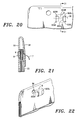
- FIG. 20 is an enlarged bottom plan view of a portion of an easel pad having a die-cut pattern in the easel pad cover in accordance with an eighth embodiment of the present invention, in which a small note pad is positioned between the front and bottom cover panels.
- FIG. 21 is a cross-sectional view of the easel pad and separate pad shown in FIG. 20 taken through line 21 - 21 .
- FIG. 22 is a back perspective view of a portion of the easel pad shown in FIG. 20 , showing the positioning of the small note pad between the bottom cover panel and front cover panel using a cut in the bottom cover panel.
- the easel pad 10 is comprised of a stack of flexible sheets 20 , preferably paper, positioned in a first major plane of the easel pad and bound to one another along an edge or margin 22 , usually the top margin of the pad, to hold the sheets 20 together in a pad-type arrangement. Staples, fasteners, adhesive (hot melt, fugitive, repositional, etc.) or other suitable pad binding methods are conventionally provided to secure the sheets to one another along the margin 22 .
- repositional adhesive is applied along the back sides of the sheets to bind the sheets together.
- the repositionable adhesive is preferably a repositionable microsphere pressure-sensitive adhesive.
- the adhesive is generally applied in the form of a strip adjacent the bound margin of the sheet, so that the individual sheets may be removed from the easel pad and adhered to another supporting surface, such as a wall.
- a separation or perforation line (not shown) optionally extends across each sheet between the binding and repositional adhesive.
- a release strip (not shown) may be provided over the adhesive on the sheets.
- the release strip may comprise a separate strip of release material or a folded portion of the sheet.
- the sheets 20 of the easel pad may be any suitable shape or size, but are preferably rectangular or square in shape. Typically, the sheets range in size from about 1.5 to three feet wide by about two to four feet high, and are more preferably about two feet wide by about three feet high.
- the sheets 20 of the present invention are made of any suitable substrate.
- the sheet material is preferably comprised of paper, vellum, or plastic film materials, such as polyethylene, polypropylene and polyester, including MYLAR® available from Dupont.
- the flexible sheet material is comprised of paper.
- the flexible sheet material may include various coatings, such as a primer coating or release coating.
- the easel pad 10 of the present invention includes a cover 30 comprised of relatively stiff material, such as those cover materials conventionally used in easel pads.
- the cover material is such that it can be repeatedly bent and folded without fracturing.
- suitable cover materials include heavy gauge paper, cardboard, polyethylene, polypropylene, vinyl, nylon, rubber, leather, various impregnated or laminated fibrous materials, various plasticized materials, and the like, and combinations of such materials (e.g., cardboard with a plastic lamination).
- the cover 30 of the easel pad 10 of the present invention is modified to include a support ledge that is well suited for holding markers, erasers, and other instruments when the easel pad is in an upright position.
- a first major plane e.g., substantially vertical or upright plane
- the support ledge extends from the cover in a second plane.
- the second plane is preferably substantially perpendicularly to the first major plane (e.g., horizontal plane) so that the instrument may rest on the support ledge without falling from the ledge.
- the substantially planar support ledge of the easel pad enables the writer or drawer to quickly and easily obtain the instrument from the pad, and deposit the instrument back on the easel pad when the writer or drawer is finished using the instrument.
- the support ledge is integrated into any suitable cover 30 design conventionally used with easel pads, such as those covers comprising a bottom cover panel 32 , a front cover panel 34 , or both panels.
- cover 30 of the easel pad with a bottom cover panel 32 that extends along the length of the bottommost sheet in the stack of flexible sheets 20 as generally illustrated in FIG. 1 .
- the bottom cover panel 32 provides stiff support for the flexible sheets 20 , which facilitates the positioning of the easel pad 10 on an easel stand.
- the bottom cover panel 32 provides a more stable and level sheet writing surface during use.
- a cover 30 having both a bottom cover panel 32 and a front cover panel 34 .
- the cover 30 may be formed by folding a unitary piece of cover material along a fold-line and then securing the stack of sheets between the “v”-shaped portion defined by the bottom cover panel 32 and front cover panel 34 .
- the bottom cover panel 32 and front cover panel 34 may alternatively be formed of separate pieces of cover material which are adhered together at a margin using conventional binding means.
- the cover 30 may optionally include one or more handles 40 useful for carrying the easel pad 10 .
- the handle 40 is usually formed in the top and center portion of the easel pad.
- the handle 40 usually comprises an elongated handle opening, such as hole or a flap (see, e.g., FIG. 9 ), in the bottom cover panel 32 of the easel pad.
- the handle 40 is typically formed by creating two complementary handle openings 42 a , 42 b in the cover material.
- Either or both complementary handle openings 42 a , 42 b may be formed by completely removing a portion of the cover 30 to form a hole.
- Either or both complementary handle openings 42 a , 42 b may also comprise a foldable flap 44 formed by cutting the cover 30 in a substantially “u”-shaped configuration.
- FIG. 2 illustrates two complementary handle openings 42 a , 42 b , each comprised of an elongated hole in the back panel 32 and another elongated hole in the front cover panel 34 of the cover.
- complementary handle opening 42 a comprises a hole in the bottom cover panel 32 while complementary handle opening 42 b comprises a foldable flap 44 formed in the front cover panel 34 by making a “u”-shaped cut and creating an upper fold-line 45 at the top of the “u.”
- the foldable flap 44 in the front cover panel 34 is usually folded upwardly so that it is positioned either: (1) against the bottom cover panel 32 in a plane substantially parallel to the plane of the bottom cover panel 32 , or (2) against the front cover panel 34 in a plane substantially parallel to the plane of the front cover panel 34 .
- the foldable flap 44 helps secure the bottom cover panel 32 and front cover panel 34 together.
- the cover 30 may also optionally include one or more hanging openings 50 adapted to receive hanging pegs or hooks that are commonly used in conjunction with easel pad stands or other suitable hanging devices on the hanging surface.
- the hanging opening 50 can be any suitable shape or size (e.g., circular, square, elongated slots, and the like).
- the cover contains a set of hanging openings 50 which are positioned on the right and left sides of the pad near the top of the pad.
- the hanging openings 50 may be formed by completely removing a portion of the cover to create a hole or by creating a foldable flap in the cover.
- each hanging opening 50 is typically formed by creating two complementary hanging openings 52 a , 52 b (e.g., holes or flaps) in the cover material. Together, the complementary hanging openings 52 a , 52 b are aligned such that they are adapted to receive the hanging pegs, hooks, and the like.
- the cover 30 of the easel pad 10 is cut and/or scored using conventional die-cutting techniques to create a blank for forming a support ledge.
- the cover 30 is then folded outwardly from the major plane of the easel pad to form the support ledge.
- the ledge is useful for supporting markers and other instruments of various shapes and sizes commonly used with easel pads.
- the die-cut pattern for forming the support ledge may optionally be integrated with the handle, hanging openings, and/or a second support ledge.
- the cover may be die-cut to provide for the placement of a separate smaller note pad within the cover such that the sheets of the note pad may be dispensed to the user.
- FIGS. 1 , 1 A, 2 , and 2 A illustrate an easel pad 10 in accordance with a first embodiment of the present invention.
- the easel pad 10 comprises a stack of flexible sheets 20 and a cover 30 having both a bottom cover panel 32 and a front cover panel 34 .
- the cover 30 includes a handle 40 made of a pair of complementary handle openings 42 a , 42 b comprised of elongated holes, as well as two lateral hanging openings 50 , each hanging opening 50 comprised of a pair of complementary holes 52 a , 52 b adapted to receive hanging pegs or hooks.
- FIGS. 1 and 1A show a first blank 100 for creating a support ledge 110 in accordance with the first embodiment of the present insertion.
- the blank 100 includes a flap 115 formed by making a generally upside-down “u”-shaped cut in the cover 30 .
- the flap 115 comprises an upper cut 120 , two side cuts 122 R, 122 L, and a lower fold-line 124 .
- the lower fold-line 124 is substantially horizontal when the easel pad is in a substantially upright or vertical position.
- flap 115 when the flap 115 is folded downwardly along lower fold-line 124 so that flap 115 is substantially perpendicular to the plane of the upright cover 30 , it forms a horizontal support ledge 110 for holding a marker or other instrument, which can be easily accessed by the user.
- the foldable flap 115 extends outwardly from the major plane of the cover 30 so that a marker or other instrument placed on the support ledge 110 will not roll or fall off the ledge when the easel pad 10 is in an upright position.
- support ledge 110 be positioned substantially perpendicular to the plane of the upright cover or be positioned at an upward angle, thereby making a “v” with the cover.
- the support ledge 110 may optionally include a lip (not shown) at the outer edge of the ledge 110 formed by making a fold near cut 120 , the lip extending upward to help keep the marker from rolling off the support ledge 110 when the easel pad is in an upright position.
- the blank 100 preferably includes additional cuts and/or folds that are used to stabilize the support ledge 110 in a removably fixed position. For example, as shown in FIG. 1A , adjacent and lateral to the lower fold-line 124 , one or more lower cuts 130 R, 130 L are provided. When the cover is folded along fold-line 132 R (which extends between the lower fold-line 124 and the upper cut 120 ), the blank creates a foldable stabilizing flap 135 R. To help stabilize the support ledge 110 , the stabilizing flap 135 R is folded out along fold-line 132 R so that the flap 135 R is substantially perpendicular to the plane of the cover 30 .
- the flap 135 R then removably engages the cover 30 , for example at the upper cut 120 or side cut 122 R, to maintain the support ledge 110 in a removably fixed position.
- the flap 135 R is also preferably removably inserted into a receiving slot 138 R in the cover 30 for additional stability.
- the blank when the cover is folded along fold-line 132 L (which extends between the lower fold-line 124 and the upper cut 120 ), the blank creates a stabilizing flap 135 L opposite the stabilizing flap 135 R.
- the flap 135 L is folded out along fold-line 132 L so that the flap 135 L is no longer in the same plane as the cover 30 .
- the flap 135 L engages the cover 30 to help maintain the support ledge 110 in a removably fixed position.
- the flap 135 L is also preferably inserted into a receiving slot 138 L in the cover 30 for additional stability.
- the edge of the stack of flexible sheets 20 is positioned within the cover 30 so that the edge is aligned with support ledge 110 .
- the support ledge 110 and the edge of the stack of flexible sheets 20 comprise a composite support ledge 112 that are together useful for holding a marker or other instrument commonly used with the easel pad 10 .
- the blank 100 is well-suited for incorporation in any suitable cover design for an easel pad.
- the blank 100 is illustrated in FIGS. 1 , 1 A, 2 and 2 A in a cover 30 comprising both a bottom cover panel 32 and a front cover panel 34
- the blank may alternatively be incorporated into a cover comprising a bottom cover panel 32 only that extends above or below the stack of flexible sheets (see, e.g., FIG. 9 ).
- the blank is most preferably formed in the front cover panel so that, as shown in FIGS. 2 and 2A , when the easel pad is placed in an upright position, bottom cover panel 32 serves as a vertical wall behind the front cover panel 34 in the area in which the support ledge 110 extends out of the plane of the front cover panel 34 .
- the bottom cover panel 32 of the cover 30 helps prevent the marker or other instrument from rolling off the support ledge 110 .
- FIGS. 3 , 3 A, 3 B, 4 , and 4 A illustrate an easel pad 10 in accordance with a second embodiment of the present invention. While only the top portion of the easel pad is shown in the figures, it will be appreciated that the remainder of the easel pad is constructed in a conventional manner.
- the easel pad 10 comprises a stack of flexible sheets 20 and a cover 30 having both a bottom cover panel 32 and a front cover panel 34 .
- the cover 30 includes handle 40 comprised of a pair of complementary handle openings 42 a , 42 b , in which the bottom complementary handle opening 42 a comprises an elongated slot in the bottom cover panel 32 and the front complementary handle opening 42 b comprises a foldable flap 44 in the front cover panel 34 .
- the cover 30 includes left and right hanging openings 50 , each haning opening comprised of a pair of complementary hanging openings 52 a , 52 b (e.g., holes) adapted to receive hanging pegs, hooks, and the like.
- each haning opening comprised of a pair of complementary hanging openings 52 a , 52 b (e.g., holes) adapted to receive hanging pegs, hooks, and the like.
- FIGS. 3 , 3 A, and 3 B depict a blank 200 for creating a support ledge 210 in accordance with a second embodiment of the present invention.
- the blank 200 of the second embodiment is similar to the first embodiment, but the handle 40 is also integrated with the support ledge 210 .
- the support ledge 210 comprises a flap 215 formed by making a generally upside-down “u”-shaped cut in the cover 30 .
- the flap 215 has an upper cut 220 , two side cuts 222 R, 222 L, and a lower fold-line 224 .
- the lower fold-line 224 be substantially horizontal when the easel pad is in a substantially upright or vertical position.
- the second blank 200 preferably includes additional cuts and/or folds that are used to stabilize the support ledge 210 .
- additional cuts and/or folds that are used to stabilize the support ledge 210 .
- one or more lower cuts 230 R, 230 L are provided adjacent to the lower fold-line 224 .
- the blank creates a stabilizing flap 235 R.
- the flap 235 R is folded out along fold-line 232 R so that the flap 235 R is substantially perpendicular to the plane of the cover 30 .
- the flap 235 R engages the upper cut 220 or side cut 222 R to maintain the support ledge 210 in a removably fixed position.
- the flap 235 R is removably inserted into a receiving slot 238 R in the upper cut 220 for additional stability.
- the blank when the cover is folded along fold-line 232 L (which extends between the lower fold-line 224 and the upper cut 220 ), the blank creates a stabilizing flap 235 L opposite the stabilizing flap 235 R.
- the flap 235 L is folded out along fold-line 232 L so that the flap 235 R is no longer in the same plane as the cover 30 .
- the flap 235 L engages the upper cut 220 to help maintain the support ledge 210 in a removably fixed position.
- the flap 235 L is also preferably inserted into receiving slot 238 L in the upper cut 220 for additional stability.
- the handle 40 of the easel pad 10 is integrated with the die-cut pattern of the support ledge 210 . That is, at least one of the cuts and/or folds that is used to form the support ledge 210 is also used to form part of the handle 40 .
- the handle 40 comprises two complementary handle openings 42 a , 42 b .
- the first complementary handle opening 42 a comprises an elongated hole 42 a in the bottom cover panel 32 .
- the second complementary handle opening 42 b comprises a foldable flap 44 formed in the front cover panel by making a generally “u”-shaped cut and creating an upper fold line 45 at the top of the “u.” At least a portion of the cut used to form the bottom of the “u” of foldable flap 44 comprises a portion of the upper cut 220 of the flap 215 used to form the support ledge 210 . As depicted in FIG. 4A , when the foldable flap 44 is folded upwardly along fold-line 45 , the handle 40 is formed.
- the blank 200 having the support ledge 210 and handle 40 is formed in any suitable cover design.
- the blank 200 is formed in an easel pad 10 having a cover 30 comprising both a bottom cover panel 32 and a front cover panel 34 , rather than a single panel.
- the complementary handle opening 42 a e.g., hole or flap
- the bottom cover panel 32 provides a vertical wall behind the front cover panel 34 in the area in which the support ledge 210 extends substantially perpendicularly from the plane of the front cover panel 34 (see FIGS. 4 and 4A ).
- the bottom cover panel 32 helps prevent the marker or other instrument from rolling off the support ledge 210 .
- the handle 40 described in the second embodiment comprises a flap/hole combination
- the handle 40 may be formed from any suitable design.
- the handle 40 may comprise a flap in the bottom cover panel and a hole in the front cover panel, a hole in the bottom cover panel and a flap in the front cover panel, a hole in the bottom cover panel and a hole in the front cover panel, or a flap in the bottom cover panel and a flap in the front cover panel.
- the blank 200 comprises a handle having a hole in the front cover panel 34
- a portion of the upper cut 220 used to form the flap 215 of the support ledge 210 is also used to form the hole of the handle 40 .
- FIGS. 5 , 5 A, 6 , and 6 A illustrate an easel pad 10 in accordance with a third embodiment of the present invention.
- the easel pad 10 comprises a stack of flexible sheets 20 and a cover 30 having both a bottom cover panel 32 and a front cover panel 34 .
- the cover 30 contains a handle 40 formed of a pair of complementary handle openings 42 a , 42 b made of circular holes, as well as two hanging openings 50 , each comprised of a pair of complementary hanging openings 52 a , 52 b (e.g., holes) that are adapted to receive hanging pegs or hooks.
- FIGS. 5 and 5A illustrate a blank 300 for creating a support ledge 310 in accordance with the third embodiment of the present invention.
- the cover includes a flap 315 formed by making a generally “u”-shaped cut in the front cover panel 34 .
- the flap 315 has an upper fold-line 324 , two side cuts 322 R, 322 L, and a lower cut 320 .
- the flap 315 is folded upwardly along upper fold-line 324 so that flap 315 is substantially perpendicular to the plane of the cover 30 , it forms a support ledge 310 for holding a marker or other instrument (see FIG. 6 ).
- the easel pad 10 is placed in an upright position, the user can easily access the marker from the support ledge 310 .
- the blank 300 preferably contains additional cuts and/or folds that are used to stabilize the support ledge 310 .
- additional cuts and/or folds that are used to stabilize the support ledge 310 .
- one or more upper cuts 330 R, 330 L are provided adjacent or near the upper fold-line 324 .
- the blank When the cover is folded along fold-line 332 R (which extends between the lower cut 320 and the upper fold-line 324 ), the blank creates a foldable stabilizing flap 335 R.
- the flap 335 R is folded out along fold-line 332 R so that the flap extends out of the plane (e.g., substantially perpendicularly) of the cover 30 .
- the flap 335 R engages the cover to help maintain the support ledge 335 in a removably fixed position.
- the flap 335 R is removably inserted into a receiving slot 338 R in the cover 30 for additional stability.
- the blank when the cover is folded along fold-line 332 L (which extends between the upper fold-line 324 and the lower cut 320 ), the blank creates a stabilizing flap 335 L opposite the stabilizing flap 335 R.
- the flap 335 L is folded out along fold-line 332 L so that the flap 335 R is no longer in the same plane as the cover 30 .
- the flap 335 L engages the cover 30 to help maintain the support ledge 310 in a removably fixed position.
- the flap 335 L is preferably inserted into a receiving slot 338 L in the cover 30 for additional stability.
- the blank 300 optionally contains additional cuts and/or folds used to create a second support ledge 360 below the support ledge 310 .
- the first support ledge 310 and second support ledge 360 can be formed with independent cuts and folds
- the blank 300 preferably integrates the die-cut pattern of the second ledge 360 with the die-cut pattern of the first support ledge 310 . That is, at least one of the cuts and/or folds that is used to form the first support ledge 310 is also used to form part of the second support ledge 360 .
- the second support ledge 360 is generally constructed in a similar manner to the ledge 110 discussed above in conjunction with the first embodiment. More specifically, the second support ledge 360 is comprised of a flap 365 having an upper cut 370 , two side cuts 372 R, 372 L, and a lower fold-line 374 . That is, the flap 365 is formed by making a generally upside-down “u”-shaped cut in the cover 30 . At least a portion of the upper cut 370 used to form the bottom of the “u”-shaped cut for lower flap 365 comprises a portion of the lower cut 320 used to form upper flap 315 .
- the lower fold-line 374 of the flap 365 is substantially horizontal when the easel pad 10 is in a partially upright or vertical position.
- the flap 365 is folded downwardly along lower fold-line 374 so that flap 365 is folded out of the plane of the cover 30 (e.g., substantially perpendicular to the plane of the substantially vertical cover 30 ) (see FIG. 6 )
- it forms a support ledge 360 for holding a marker or other instruments, which can be easily accessed by the user.
- the second support ledge 360 be substantially horizontal when the easel pad 10 is in an upright position.
- the stabilizing flaps 335 R, 335 L are preferably removably inserted into receiving slots 338 R, 338 L in the second ledge 360 for additional stability.
- the blank 300 comprises one or more flaps 335 R, 335 L which function to stabilize both the first ledge 310 and the second ledge 360 .
- the first ledge 310 optionally contains one or more holes 312 for removably receiving a writing instrument or other elongated object in a substantially vertical position. As shown in FIG. 6A , the writing instruments 5 are inserted through the holes 312 and rest on the second ledge 360 , which is positioned below the first ledge 310 .
- the second ledge 360 may optionally include one or more smaller holes 362 for receiving a portion of the writing instrument or other elongated object.
- the smaller holes 362 are sized so that the elongated object is not permitted to fall through the smaller holes 362 , but instead the smaller holes 362 retain the elongated object in a removably fixed position.
- the stabilizing flaps 335 R, 335 L may also contain one or more flap holes 336 for receiving a marker or other writing instrument.
- the marker may be inserted into the flap holes 336 so that the marker rests at an incline on the second support ledge 360 .
- An additional flap hole (not shown) could optionally be formed in stabilizing flap 335 L to hold the marker in a substantially horizontal position.
- the marker is inserted through a first flap hole 336 in stabilizing flap 335 R and through second flap hole (not shown) in stabilizing flap 335 L.
- the flap hole 336 in stabilizing flap 335 R also functions as the complementary opening 52 b adapted to receive a support peg for hanging the easel pad 10 .
- the blank 300 can be formed in any suitable cover 30 .
- the blank 300 is formed in an easel pad 10 having a cover 30 comprising both a bottom cover panel 32 and a front cover panel 34 , rather than a single panel.
- the blank is most preferably formed in the front cover panel 34 .
- the bottom cover panel 32 provides a vertical wall behind the front cover panel 34 in the area in which the second support ledge 360 extends substantially perpendicularly from the plane of the front cover panel 34 .
- the bottom cover panel 32 helps prevent the marker or other writing instrument from rolling backwards off the support ledge 360 .
- FIGS. 7 , 8 , and 8 A illustrate an easel pad 10 in accordance with a fourth embodiment of the present invention.
- the easel pad 10 comprises a stack of flexible sheets 20 and a cover 30 having both a bottom cover panel 32 and a front cover panel 34 .
- the cover 30 also contains a handle 40 comprised of a pair of complementary handle openings 42 a , 42 b , in which the bottom complementary handle opening 42 a is an elongated slot in the bottom cover panel 32 and the front complementary handle opening 42 b is a foldable flap 44 in the front cover panel 34 .
- the cover 30 includes two lateral hanging openings 50 comprised of complementary hanging openings 52 a , 52 b (e.g., holes) adapted to receive hanging pegs or hooks.
- FIG. 7 shows a blank 400 for creating a support ledge 410 in accordance with the fourth embodiment of the present invention.
- the support ledge 410 comprises a flap 415 of any suitable shape or size.
- the flap 415 is preferably formed by making a generally “u”-shaped cut in the cover 30 .
- the flap 415 has an upper fold-line 424 , two side cuts 422 R, 422 L, and a lower cut 420 .
- the flap 415 is folded upwardly along upper fold-line 424 so that flap 415 is substantially perpendicular to the plane of the cover 30 , it forms a support ledge 410 for holding a marker or other writing instrument (see FIG. 8 ).
- the easel pad 10 is placed in an upright position, the user can easily access the marker from the support ledge 410 .
- the blank 400 optionally contains additional cuts and/or folds used to create a second support ledge 460 below the support ledge 410 .
- the first support ledge 410 and second support ledge 460 can be formed with independent cuts and folds
- the blank 400 preferably integrates the second ledge 460 with the die-cut pattern of the first support ledge 410 . That is, at least one of the cuts and/or folds that is used to form the first support ledge 410 is also used to form part of the second support ledge 460 .
- the second ledge 460 is generally constructed in a similar way to the ledge 110 discussed above in conjunction with the first embodiment. More specifically, the flap 465 comprises an upper cut 470 , two side cuts 472 R, 472 L, and a lower fold-line 474 . That is, the flap 465 is formed by making a generally upside-down “u”-shaped cut in the cover 30 . At least a portion of the cut used to form the bottom of the upside-down “u” for flap 465 comprises a portion of the lower cut 420 used to form flap 415 so that the first support ledge 410 and second support ledge 460 are integrally formed together.
- the lower fold-line 474 is substantially horizontal when the easel pad is in a substantially upright or vertical position.
- flap 465 is folded downwardly along lower fold-line 474 so that flap 465 is substantially perpendicular to the plane of the substantially vertical cover 30 (see FIG. 8 ), it forms a substantially horizontal support ledge 460 for holding a marker or other writing instrument, which can be easily accessed by the user.
- the blank 400 preferably contains additional cuts and/or folds that are used to stabilize the support ledge 410 and/or support ledge 460 .
- additional cuts and/or folds that are used to stabilize the support ledge 410 and/or support ledge 460 .
- one or more lower cuts 480 R, 480 L are provided adjacent or near the lower fold-line 474 .
- the cover is folded along fold-line 482 R (which extends between the lower fold-line 474 of lower flap 465 and the lower cut 420 of upper flap 415 )
- the blank creates a foldable stabilizing flap 485 R.
- the flap 485 R is folded out along fold-line 482 R so that the flap extends out of the plane (e.g., substantially perpendicularly) from the cover 30 .
- the flap 485 R engages the cover 30 to help maintain the support ledge 460 in a removably fixed position.
- the flap 485 R may contain a notch 483 R for removable insertion into a receiving slot
- the blank when the cover is folded along fold-line 482 L (which extends between the lower fold-line 474 of lower flap 465 and the lower cut 420 of upper flap 415 ), the blank creates a stabilizing flap 485 L opposite to the stabilizing flap 485 R.
- the flap 485 L is folded out along fold-line 482 L so that the flap 485 R is no longer in the same plane as the cover 30 .
- the flap 485 L engages the cover 30 to help maintain the support ledge 460 in a removably fixed position.
- the flap 485 L also preferably contains a notch 483 L for insertion into receiving slot 488 L in the cover 30 for additional stability.
- the flaps 485 R, 485 L are preferably inserted into receiving slots 488 R, 488 L in the first ledge 410 for additional stability.
- the blank 400 comprises one or more flaps which function to stabilize both the first support ledge 410 and the second support ledge 460 .
- the blank 400 comprises a handle 40 that is integrated with the die-cut pattern of the support ledge 410 . That is, at least one of the cuts and/or folds that is used to form the support ledge 410 also forms part of the handle 40 .
- the flap 415 for forming support ledge 410 also functions as a handle 40 . That is, the foldable flap 415 which is used to form the support ledge 410 can be folded upwardly so that it is positioned either: (1) against the bottom cover panel in a plane substantially parallel to the bottom cover panel 32 (see generally FIG. 4A ), or (2) against the front cover panel in a plane substantially parallel to the front cover panel 34 (see FIG. 8A ). When folded, the flap creates complementary handle opening 42 b .
- the bottom cover panel 32 contains a complementary handle opening 42 a which at least partially overlaps complementary handle opening 42 b in the front cover panel.
- the complementary handle opening 42 a in the bottom cover panel be sized and shaped such that the bottom cover panel 32 creates at vertical wall behind the front cover panel 34 in the area in which the support ledge 460 extends substantially perpendicularly from the plane of the easel pad (see FIG. 8 ).
- the bottom cover panel 32 helps prevent the marker or other writing instrument from rolling off the support ledge 460 .
- the first ledge 410 contains one or more holes 412 for removably receiving a writing instrument or other elongated object in a substantially vertical position.
- the second ledge 460 and/or stabilizing flaps 485 R, 485 L may also contain holes for receiving a writing instrument as generally set forth in the fourth embodiment.
- FIGS. 9 , 10 and 11 illustrate an easel pad 10 with a support ledge 510 in accordance with a fifth embodiment of the present invention.
- the easel pad 10 comprises a stack of flexible sheets 20 and a cover 30 comprising a bottom cover panel 32 , a handle 40 comprised of a foldable flap in the bottom cover panel 32 .
- the cover 30 includes two lateral hanging openings 50 adapted to receive hanging pegs or hooks.
- the bottom cover panel 32 of the cover 30 extends below the stack of flexible sheets 20 .
- the bottom cover panel 32 is folded below the stack of flexible sheets near the lower margin along fold-line 524 .
- the fold-line 524 preferably traverses the entire width of the cover 30 .
- the support ledge 510 is formed by folding the bottom cover panel 32 upwardly at the fold-line 524 so that the support ledge 510 extends outwardly from, and preferably substantially perpendicular to the plane of the cover 30 or at an upward angle, thereby making a “v” with the cover.
- the support ledge 510 when the easel pad 10 is in a substantially upright or vertical position, the support ledge 510 is in a substantially horizontal plane so that the support ledge is well-adapted for holding a marker or other writing instrument, which can be easily accessed by the user.
- the support ledge 510 may optionally contain a lip (not shown) that extends upward to help keep the writing instrument from rolling off the support ledge 510 .
- the blank 500 for forming the support ledge 510 preferably contains additional cuts and/or folds that are used to stabilize the support ledge 510 .
- one or more stabilizing flaps 535 R, 535 L are provided in the blank 500 .
- the stabilizing flaps 535 R, 535 L are any suitable size and shape, but are preferably comprised of generally sideways “u”-shaped cuts in the cover 30 . More specifically, a lower cut 530 R is provided near fold-line 524 . Above fold-line 524 is a side cut 522 R, upper cut 520 R, and a side fold-line 532 R (which extends from upper cut 520 R toward the fold-line 524 ).
- the bottom cover panel 32 is folded out along side fold-line 532 R to form stabilizing flap 535 R.
- the stabilizing flap 532 R preferably forms between about a 30 to 90 degree angle with the plane of the bottom cover panel 32 , and most preferably between about a 50 to 70 degree angle with the plane of the cover.
- the stabilizing flap 535 R engages a stabilizing flange 570 R formed from the blank 500 in the bottom cover panel 32 .
- the stabilizing flange 570 R is preferably integrated with the stabilizing flap 535 R. That is, at least one of the cuts and/or folds that is used to form the stabilizing flange 570 R also forms part of the stabilizing flap 535 R.
- the stabilizing flange 570 R comprises a generally upside down “u”-shaped cut in the bottom cover panel 32 .
- the stabilizing flange 570 R includes a side cut 578 R which extends between the side fold-line 532 R and the lower cut 530 R of the stabilizing flap 535 R.
- the stabilizing flap 535 R preferably contains a notch 533 R which is removably inserted into a receiving slot 588 R in the stabilizing flange 570 R for additional stability.
- the support ledge 510 and the stabilizing flange 570 R are preferably in the same plane but extend outwardly from the plane of the cover 30 in opposite directions. Specifically, as shown in FIG. 11 , the support ledge 510 extends out toward the front of the easel pad 10 , while the stabilizing flange 570 R extends out toward the bottom of the easel pad 10 .
- Stabilizing flap 535 L is formed in a similar fashion.
- a lower cut 530 L is provided along or just below lower fold-line 524 .
- Above fold-line 524 is a side cut 522 L, upper cut 520 L, and a side fold-line 532 L (which extends from upper cut 520 L toward the fold-line 524 ).
- the bottom cover panel 32 is folded out along side fold-line 532 L to form the stabilizing flap 535 L.
- the stabilizing flap 532 forms between about a 30 to 90 degree angle with the plane of the bottom cover panel 32 , and most preferably between about a 50 to 70 degree angle with the plane of the cover.
- the stabilizing flap 535 L engages a stabilizing flange 570 L formed from the blank 500 in the bottom cover panel 32 .
- the stabilizing flange 570 L is preferably integrated with the stabilizing flap 535 L. That is, at least one of the cuts and/or folds that is used to form the stabilizing flange 570 L also forms part of the stabilizing flap 535 L.
- the stabilizing flange 570 L comprises a generally upside down “u”-shaped cut in the bottom cover panel 32 .
- the stabilizing flange 570 L includes a side cut 578 L which extends between the side fold-line 532 L and the lower cut 530 L of the stabilizing flap 535 L.
- the stabilizing flap 535 L preferably contains a notch 533 L which is removably inserted into a receiving slot 588 L in the stabilizing flange 570 L for additional stability.
- the support ledge 510 and the stabilizing flange 570 L are preferably in the same plane but extend outwardly from the plane of the cover 30 in opposite directions.
- the support ledge 510 extend up towards the front of the easel pad 10
- the stabilizing flange 570 L extends down towards the bottom of the easel pad 10 .
- FIGS. 12 , 13 , 14 , and 15 illustrate an easel pad 10 with a support ledge 610 in accordance with a sixth embodiment of the present invention.
- the support ledge 610 is adapted for holding a separate smaller pad 6 of flexible sheets so that the sheets 7 can be easily accessed by the user/drawer when using the easel pad 10 .
- the support ledge 610 comprises the edge of the stack of flexible sheets, which is positioned between the bottom cover panel 32 and the front cover panel 34 of the cover 30 .
- An opening such as an elongated slot 38 , is formed in at least one of either the bottom cover panel 32 or the front cover panel 34 of the cover, most preferably the front cover panel 34 .
- the separate pad 6 of flexible sheets is positioned between the bottom cover panel 32 and the front cover panel 34 of the cover 30 so that at least one sheet in the separate pad 6 extends through the slot 38 in the cover 30 .
- the support ledge 610 helps keep the separate pad 6 in a fixed position between the bottom cover panel 32 and front cover panel 34 of the cover 30 .
- the separate pad 6 of sheets can be made of any suitable material and can be any suitable shape and size. Such pads are well-known in the art, and are commercially available by various manufacturers.
- the pad 6 comprises a stack of rectangular-shaped flexible sheets 7 comprised of paper. Each has a first major surface and an opposite second major surface extending between two substantially opposite edges. Each sheet has repositionable adhesive along one edge and is free of adhesive along the opposite edge. The sheets are stacked with the repositionable adhesive edge of each sheet disposed along alternate opposite edges to maintain the sheets in the stack.
- Such pads 6 are generally described in U.S. Pat. Nos. 5,417,345 and 6,669,992, which are incorporated by reference. As generally shown in FIG.
- the sheets 7 are preferably dispensed one at a time from the slot 38 in the cover 30 of the easel pad 10 , the top sheet of the note pad 6 designed to be easily removed from the note pad, and at the same time pull the adjacent sheet through the slot 38 .
- the cover 30 may also contain additional cuts and/or folds to help stabilize the pad 6 on the support ledge 610 between the bottom cover panel 32 and front cover panel 34 .
- FIG. 15 illustrates two stabilizing flaps 635 R, 635 L that are die-cut into the bottom cover panel 32 .
- Each stabilizing flap 635 R, 635 L extends from the bottom cover panel 32 and is positioned on one side of the note pad 6 to help retain the note pad 6 within the cover.
- the fold-line for each flap 635 R, 635 L is located more centrally than the more laterally positioned “u”shaped cut of the flaps 635 R, 635 L relative to the pad 6 .
- the stabilizing flaps 635 R, 635 L each preferably contain a notch 633 R, 633 L for removably engaging a corresponding receiving opening (e.g., slot) in the front cover 34 .
- FIGS. 16 , 17 , 18 , and 19 illustrate an easel pad 10 with a support ledge 710 in accordance with a seventh embodiment of the present invention.
- This embodiment is similar to the sixth embodiment except that the support ledge 710 adapted for holding a separate smaller pad 6 is formed from the cover 30 , instead of the edge of the stack of flexible sheets 20 .
- the easel pad 10 is die-cut so that the sheets 7 of the smaller pad 6 can be easily accessed by the user/drawer when using the easel pad 10 .
- the support ledge 710 comprises a flap 715 formed by making a generally upside-down “u”-shaped cut in the bottom cover panel 32 of the cover 30 .
- the lower fold-line 724 is substantially horizontal when the easel pad is in a substantially upright or vertical position.
- the flap 715 is folded downwardly along lower fold-line 724 so that the flap 715 is substantially perpendicular to the plane of the upright cover 30 , it forms a horizontal support ledge 710 for holding the pad between the front cover panel 34 and bottom cover panel 32 of the cover.
- An opening, such as an elongated slot 38 is formed in the front cover panel 34 . At least one sheet in the separate pad 6 extends through the slot 38 in the cover 30 .
- the support ledge 710 extends at least partially between the gap created between the bottom cover panel 32 and the front cover panel 34 (see FIG. 18 ). Alternatively, the support ledge 710 may traverse the entire gap between the bottom cover panel 32 and the front cover panel 34 .
- the support ledge 710 may also contain a notch for removably engaging a corresponding slot (not shown) in the front cover panel 34 .
- the cover 30 may also contain additional cuts and/or folds to help stabilize the pad 6 on the support ledge 710 between the bottom cover panel and front cover panel.
- FIGS. 17 and 19 illustrate two stabilizing flaps 735 R, 735 L that are die-cut into the bottom cover panel 32 .
- Each stabilizing flap 735 R, 735 L extends from the bottom cover panel 32 and is positioned on one side of the note pad 6 to help retain the note pad 6 within the cover.
- the fold-line for each flap 735 R, 735 L is located more laterally than the more centrally positioned “u”-shaped cut of the flaps 735 R, 735 L relative to the pad 6 .
- the stablizing flaps 735 R, 735 L may optionally engage an opening (not shown) in the front cover panel to help secure the flaps 735 R, 735 L in a removably fixed position.
- FIGS. 20 , 21 , and 22 illustrate an easel pad 10 with in accordance with an eighth embodiment of the present invention.
- This embodiment is similar to the sixth and seventh embodiments insofar as a separate smaller pad is retained within the cover. In the eighth embodiment, however, that there is no support ledge holding the separate smaller pad 6 . Instead, the smaller pad 6 is positioned within the cover 30 by removably or permanently positioning the bottommost sheet 8 of the pad 6 in or against the bottom panel 32 of the cover in a fixed position.
- the bottommost sheet in the pad 6 may be secured to the cover 30 using adhesive, staples, tape, and the like (not shown). As such, the pad 6 is retained in a permanently fixed position between the bottom cover panel 32 and the front cover panel 34 .
- the bottom cover panel 32 contains one or more cuts through which the bottommost sheet of the pad 6 is removably secured to the bottom cover panel 32 .
- FIG. 20 illustrates a right cut (comprising right top cut 820 R, right side cut 822 R, and right bottom cut 830 R) and a left cut (comprising left top cut 820 L, left side cut 822 L, and left bottom cut 830 L).
- the bottommost sheet 8 of the pad 6 is positioned through the top cuts 820 R, 820 L and then down along the side cuts 822 R, 822 L and then through the bottom cuts 830 R, 830 L.
- a set of right and left “u”-shaped cuts are formed in the bottom cover panel 32 which operate to retain the separate pad 6 against the bottom cover panel 32 in a removably fixed position.
- the bottommost sheet 8 is essentially threaded through the various cuts to maintain the separate pad 6 in a removably fixed position. Because the bottommost sheet 8 is secured to the remainder the sheets in the pad (e.g., by virtue of adhesive or other conventional binding techniques), the entire pad 6 is retained and positioned within the cover 30 .
- an opening such as an elongated slot 38 , is formed in the front cover panel 34 . At least one sheet in the separate pad 6 extends through the slot 38 in the cover 30 .
- the bottommost sheet 8 may comprise a sheet member of the smaller stack 6 of flexible sheets or a different sheet material (e.g., a backer or release material commonly used with note pads).
- more than one sheet in the pad 6 may be positioned through the various cut(s) in the bottom cover panel to removably secure the pad 6 to the cover.
- the separate pad 6 could be maintained within the pad using a variety of cut patterns in the bottom cover panel 32 , in addition to those illustrated in the drawings.
- the bottommost sheet 8 could simply be placed through a single substantially horizontal cut in the bottom cover panel 32 that is equal to or slightly longer than the width of the separate pad The bottommost sheet 8 could then optionally be place through another single substantially horizontal cut on the bottom cover panel that is positioned below the first horizontal cut.
Landscapes
- Tables And Desks Characterized By Structural Shape (AREA)
Abstract
Description
Claims (23)
Priority Applications (1)
| Application Number | Priority Date | Filing Date | Title |
|---|---|---|---|
| US11/110,524 US7789430B2 (en) | 2005-04-20 | 2005-04-20 | Easel pad |
Applications Claiming Priority (1)
| Application Number | Priority Date | Filing Date | Title |
|---|---|---|---|
| US11/110,524 US7789430B2 (en) | 2005-04-20 | 2005-04-20 | Easel pad |
Publications (2)
| Publication Number | Publication Date |
|---|---|
| US20060237620A1 US20060237620A1 (en) | 2006-10-26 |
| US7789430B2 true US7789430B2 (en) | 2010-09-07 |
Family
ID=37185882
Family Applications (1)
| Application Number | Title | Priority Date | Filing Date |
|---|---|---|---|
| US11/110,524 Expired - Fee Related US7789430B2 (en) | 2005-04-20 | 2005-04-20 | Easel pad |
Country Status (1)
| Country | Link |
|---|---|
| US (1) | US7789430B2 (en) |
Cited By (7)
| Publication number | Priority date | Publication date | Assignee | Title |
|---|---|---|---|---|
| US20100243854A1 (en) * | 2009-03-24 | 2010-09-30 | Logue C Robert | Presentation pad easel |
| USD662329S1 (en) | 2011-04-22 | 2012-06-26 | Steelcase Inc. | Furniture piece |
| US10118434B2 (en) * | 2016-09-16 | 2018-11-06 | Arden L. Thorsbakken | Caddy valet with spaced adhesive |
| US20190184733A1 (en) * | 2017-04-18 | 2019-06-20 | King Jim Co., Ltd. | File |
| US11278165B2 (en) | 2017-05-24 | 2022-03-22 | Kimberly-Clark Worldwide, Inc. | Sewn stack of absorbent sheets |
| US11299305B2 (en) | 2017-05-24 | 2022-04-12 | Kimberly-Clark Worldwide, Inc. | Sewn stack of absorbent sheets |
| US12049100B1 (en) * | 2013-11-13 | 2024-07-30 | Ronald Bowie | Portable dry erase board with carrying case |
Families Citing this family (1)
| Publication number | Priority date | Publication date | Assignee | Title |
|---|---|---|---|---|
| USD1096938S1 (en) | 2022-08-11 | 2025-10-07 | ACCO Brands Corporation | Pocket with surface indicia |
Citations (34)
| Publication number | Priority date | Publication date | Assignee | Title |
|---|---|---|---|---|
| US736810A (en) | 1903-04-22 | 1903-08-18 | William H Wynans | Combination pen and pencil receptacle tablet. |
| US1176786A (en) | 1915-10-06 | 1916-03-28 | Eberhard Faber Pencil Company | Display-holder. |
| US1386700A (en) | 1918-08-15 | 1921-08-09 | Francis R Gilbert | Pocket pencil, pen, and pad holder |
| US2024984A (en) | 1934-06-11 | 1935-12-17 | Irwin C Bradley | Display card |
| US2486840A (en) * | 1945-07-06 | 1949-11-01 | Slencil Co | Pencil-carrying memorandum pad or book |
| US2606041A (en) * | 1948-05-01 | 1952-08-05 | Jr John F Misiak | Notebook |
| US2726835A (en) * | 1951-02-06 | 1955-12-13 | Hummel Robert Stuart | Collapsible display stands |
| US2738061A (en) | 1951-11-05 | 1956-03-13 | William Roberts Company Inc | Display card |
| US3188113A (en) | 1963-06-10 | 1965-06-08 | Carroll N Cross | Paper holder with v-shaped pen receptacle |
| US3778324A (en) * | 1968-12-30 | 1973-12-11 | J Lavigne | Pad of stacked detachable sheets,and method and elements for manufacturing the same |
| US4002237A (en) | 1975-05-05 | 1977-01-11 | Winthrop-Atkins Co., Inc. | Pencil caddy |
| US4066171A (en) | 1976-02-17 | 1978-01-03 | Fowlie William J C | Desk stand for holding in operative position pocket calculators and other desk-top articles |
| US4105182A (en) * | 1977-01-12 | 1978-08-08 | Jacobson Samuel O | Multiple use study device |
| US4318471A (en) | 1980-04-24 | 1982-03-09 | Hutton Robert P | Artist's lap easel |
| US4395056A (en) * | 1980-10-16 | 1983-07-26 | Mille Note System S.R.L. | Note booklet, provided with a foldable cover, effective to act as a sheet and pen holder |
| US5007192A (en) | 1988-10-19 | 1991-04-16 | Nelson Hochberg | Lapboard |
| US5334094A (en) * | 1992-09-21 | 1994-08-02 | Minnesota Mining And Manufacturing Company | Carbonless pad assembly |
| US5351992A (en) | 1994-02-09 | 1994-10-04 | Douglas Chilson | Itinerary planner |
| US5697518A (en) * | 1996-06-18 | 1997-12-16 | Minnesota Mining And Manufacturing Company | Header padded stationery equipped with adhesive sheet pads recessed within the header |
| US5788080A (en) * | 1997-07-14 | 1998-08-04 | Inno-Pak, Inc. | Stacked openable and reclosable plastic bags on a dispenser |
| US5874144A (en) * | 1996-10-23 | 1999-02-23 | Minnesota Mining And Manufacturing Company | Silicon-free copolymer and bleed-through resistant, ink receptive, and adhesive receptive coatings and coated substrates prepared therefrom |
| US5996778A (en) | 1997-12-09 | 1999-12-07 | Two Powers Enterprise Co., Ltd. | Structure of markers box |
| US6102199A (en) | 1998-11-17 | 2000-08-15 | Ho; Peter Pei-Tak | Hangtag notepaper dispenser and writing instrument holder |
| US6299119B1 (en) | 1999-12-22 | 2001-10-09 | David J. Dunning | Notepad attachment apparatus |
| US20010040207A1 (en) | 2000-04-13 | 2001-11-15 | Richardson James C. | Portable display board system |
| US6382864B1 (en) | 2000-03-16 | 2002-05-07 | The Mead Corporation | Folder with retaining tab |
| US6536803B2 (en) | 2000-08-16 | 2003-03-25 | Sofos Partnership Limited | Folder |
| US6543615B2 (en) * | 2000-07-18 | 2003-04-08 | Gary F. Lake | Device for holding writing implements |
| US6612771B1 (en) * | 2002-12-27 | 2003-09-02 | Ken-Jui Su | Loose leaf binding device |
| US6682798B1 (en) * | 2000-08-02 | 2004-01-27 | Ccl Label, Inc. | Expanded content device pouch |
| US20040229193A1 (en) * | 2003-05-14 | 2004-11-18 | Larry Wittmeyer | Coloring paper having adhesive |
| US20060125229A1 (en) * | 2004-12-13 | 2006-06-15 | Ray Gustav A | Easel pad |
| US7094454B2 (en) * | 2004-01-23 | 2006-08-22 | Taiwan Hopax Chems. Mfg. Co., Ltd. | Multi-color multi-ply note pad |
| US7360960B2 (en) * | 2005-05-26 | 2008-04-22 | James Hite | Notepad with embedded writing instrument |
-
2005
- 2005-04-20 US US11/110,524 patent/US7789430B2/en not_active Expired - Fee Related
Patent Citations (34)
| Publication number | Priority date | Publication date | Assignee | Title |
|---|---|---|---|---|
| US736810A (en) | 1903-04-22 | 1903-08-18 | William H Wynans | Combination pen and pencil receptacle tablet. |
| US1176786A (en) | 1915-10-06 | 1916-03-28 | Eberhard Faber Pencil Company | Display-holder. |
| US1386700A (en) | 1918-08-15 | 1921-08-09 | Francis R Gilbert | Pocket pencil, pen, and pad holder |
| US2024984A (en) | 1934-06-11 | 1935-12-17 | Irwin C Bradley | Display card |
| US2486840A (en) * | 1945-07-06 | 1949-11-01 | Slencil Co | Pencil-carrying memorandum pad or book |
| US2606041A (en) * | 1948-05-01 | 1952-08-05 | Jr John F Misiak | Notebook |
| US2726835A (en) * | 1951-02-06 | 1955-12-13 | Hummel Robert Stuart | Collapsible display stands |
| US2738061A (en) | 1951-11-05 | 1956-03-13 | William Roberts Company Inc | Display card |
| US3188113A (en) | 1963-06-10 | 1965-06-08 | Carroll N Cross | Paper holder with v-shaped pen receptacle |
| US3778324A (en) * | 1968-12-30 | 1973-12-11 | J Lavigne | Pad of stacked detachable sheets,and method and elements for manufacturing the same |
| US4002237A (en) | 1975-05-05 | 1977-01-11 | Winthrop-Atkins Co., Inc. | Pencil caddy |
| US4066171A (en) | 1976-02-17 | 1978-01-03 | Fowlie William J C | Desk stand for holding in operative position pocket calculators and other desk-top articles |
| US4105182A (en) * | 1977-01-12 | 1978-08-08 | Jacobson Samuel O | Multiple use study device |
| US4318471A (en) | 1980-04-24 | 1982-03-09 | Hutton Robert P | Artist's lap easel |
| US4395056A (en) * | 1980-10-16 | 1983-07-26 | Mille Note System S.R.L. | Note booklet, provided with a foldable cover, effective to act as a sheet and pen holder |
| US5007192A (en) | 1988-10-19 | 1991-04-16 | Nelson Hochberg | Lapboard |
| US5334094A (en) * | 1992-09-21 | 1994-08-02 | Minnesota Mining And Manufacturing Company | Carbonless pad assembly |
| US5351992A (en) | 1994-02-09 | 1994-10-04 | Douglas Chilson | Itinerary planner |
| US5697518A (en) * | 1996-06-18 | 1997-12-16 | Minnesota Mining And Manufacturing Company | Header padded stationery equipped with adhesive sheet pads recessed within the header |
| US5874144A (en) * | 1996-10-23 | 1999-02-23 | Minnesota Mining And Manufacturing Company | Silicon-free copolymer and bleed-through resistant, ink receptive, and adhesive receptive coatings and coated substrates prepared therefrom |
| US5788080A (en) * | 1997-07-14 | 1998-08-04 | Inno-Pak, Inc. | Stacked openable and reclosable plastic bags on a dispenser |
| US5996778A (en) | 1997-12-09 | 1999-12-07 | Two Powers Enterprise Co., Ltd. | Structure of markers box |
| US6102199A (en) | 1998-11-17 | 2000-08-15 | Ho; Peter Pei-Tak | Hangtag notepaper dispenser and writing instrument holder |
| US6299119B1 (en) | 1999-12-22 | 2001-10-09 | David J. Dunning | Notepad attachment apparatus |
| US6382864B1 (en) | 2000-03-16 | 2002-05-07 | The Mead Corporation | Folder with retaining tab |
| US20010040207A1 (en) | 2000-04-13 | 2001-11-15 | Richardson James C. | Portable display board system |
| US6543615B2 (en) * | 2000-07-18 | 2003-04-08 | Gary F. Lake | Device for holding writing implements |
| US6682798B1 (en) * | 2000-08-02 | 2004-01-27 | Ccl Label, Inc. | Expanded content device pouch |
| US6536803B2 (en) | 2000-08-16 | 2003-03-25 | Sofos Partnership Limited | Folder |
| US6612771B1 (en) * | 2002-12-27 | 2003-09-02 | Ken-Jui Su | Loose leaf binding device |
| US20040229193A1 (en) * | 2003-05-14 | 2004-11-18 | Larry Wittmeyer | Coloring paper having adhesive |
| US7094454B2 (en) * | 2004-01-23 | 2006-08-22 | Taiwan Hopax Chems. Mfg. Co., Ltd. | Multi-color multi-ply note pad |
| US20060125229A1 (en) * | 2004-12-13 | 2006-06-15 | Ray Gustav A | Easel pad |
| US7360960B2 (en) * | 2005-05-26 | 2008-04-22 | James Hite | Notepad with embedded writing instrument |
Cited By (9)
| Publication number | Priority date | Publication date | Assignee | Title |
|---|---|---|---|---|
| US20100243854A1 (en) * | 2009-03-24 | 2010-09-30 | Logue C Robert | Presentation pad easel |
| US8162281B2 (en) * | 2009-03-24 | 2012-04-24 | Logue C Robert | Presentation pad easel |
| USD662329S1 (en) | 2011-04-22 | 2012-06-26 | Steelcase Inc. | Furniture piece |
| US12049100B1 (en) * | 2013-11-13 | 2024-07-30 | Ronald Bowie | Portable dry erase board with carrying case |
| US10118434B2 (en) * | 2016-09-16 | 2018-11-06 | Arden L. Thorsbakken | Caddy valet with spaced adhesive |
| US20190184733A1 (en) * | 2017-04-18 | 2019-06-20 | King Jim Co., Ltd. | File |
| US10814664B2 (en) * | 2017-04-18 | 2020-10-27 | King Jim Co., Ltd. | File |
| US11278165B2 (en) | 2017-05-24 | 2022-03-22 | Kimberly-Clark Worldwide, Inc. | Sewn stack of absorbent sheets |
| US11299305B2 (en) | 2017-05-24 | 2022-04-12 | Kimberly-Clark Worldwide, Inc. | Sewn stack of absorbent sheets |
Also Published As
| Publication number | Publication date |
|---|---|
| US20060237620A1 (en) | 2006-10-26 |
Similar Documents
| Publication | Publication Date | Title |
|---|---|---|
| US6925739B1 (en) | Calendar box and stand | |
| US7325343B2 (en) | Display board system | |
| US7527235B2 (en) | Greeting card holder | |
| US6439611B1 (en) | File folder, box and panel designed with pre-perforated holes, grooves and slots | |
| US20020162935A1 (en) | Support device | |
| US7334768B1 (en) | Collapsible music book stand | |
| US7789430B2 (en) | Easel pad | |
| US11004368B2 (en) | Easel | |
| US6095565A (en) | Bookmark and pocket assembly for books | |
| US7676969B2 (en) | Kinetic display assembly | |
| US20060151585A1 (en) | Divider for storage box | |
| US6253922B1 (en) | Carpet sample book | |
| US7356953B2 (en) | Kinetic display assembly | |
| US20090001706A1 (en) | Self-adhesive message panel | |
| US5073059A (en) | Visual display supporting structure | |
| US20060273573A1 (en) | Easel pad with adhesive-containing patch | |
| US9259106B2 (en) | Removable reusable support stand | |
| US5673942A (en) | Container for notepaper | |
| US20030110672A1 (en) | Photo album page systems | |
| JP6719929B2 (en) | Book stand | |
| US20070125925A1 (en) | Desk pad with easel | |
| US8109019B2 (en) | Presentation pad supporting use of each of two sheet sides | |
| KR20210024936A (en) | Desk calendar with pen stand | |
| JPS641092Y2 (en) | ||
| KR200427836Y1 (en) | Multifunctional Folding Calendar |
Legal Events
| Date | Code | Title | Description |
|---|---|---|---|
| AS | Assignment |
Owner name: CARDINAL BRANDS, INC., KANSAS Free format text: ASSIGNMENT OF ASSIGNORS INTEREST;ASSIGNORS:WITTMEYER, LARRY, JR.;SPARKS, LANCE;SIGNING DATES FROM 20050401 TO 20050411;REEL/FRAME:016495/0567 Owner name: CARDINAL BRANDS, INC., KANSAS Free format text: ASSIGNMENT OF ASSIGNORS INTEREST;ASSIGNORS:WITTMEYER, LARRY, JR.;SPARKS, LANCE;REEL/FRAME:016495/0567;SIGNING DATES FROM 20050401 TO 20050411 |
|
| STCF | Information on status: patent grant |
Free format text: PATENTED CASE |
|
| FPAY | Fee payment |
Year of fee payment: 4 |
|
| SULP | Surcharge for late payment | ||
| AS | Assignment |
Owner name: R. R. DONNELLEY & SONS COMPANY, ILLINOIS Free format text: MERGER;ASSIGNOR:MOORE WALLACE NORTH AMERICA, INC.;REEL/FRAME:039876/0425 Effective date: 20121231 Owner name: MOORE WALLACE NORTH AMERICA, INC., ILLINOIS Free format text: MERGER;ASSIGNOR:CB HOLDINGS, INC.;REEL/FRAME:039876/0373 Effective date: 20071228 Owner name: CB HOLDINGS, INC., ILLINOIS Free format text: MERGER;ASSIGNOR:CARDINAL BRANDS, INC.;REEL/FRAME:040169/0875 Effective date: 20071228 Owner name: LSC COMMUNICATIONS US, LLC, ILLINOIS Free format text: ASSIGNMENT OF ASSIGNORS INTEREST;ASSIGNOR:R. R. DONNELLEY & SONS COMPANY;REEL/FRAME:040172/0401 Effective date: 20160901 |
|
| AS | Assignment |
Owner name: WELLS FARGO BANK, NATIONAL ASSOCIATION, AS COLLATE Free format text: SECURITY AGREEMENT;ASSIGNOR:LSC COMMUNICATIONS US, LLC;REEL/FRAME:040213/0791 Effective date: 20160930 Owner name: BANK OF AMERICA, N.A., AS ADMINISTRATIVE AGENT, TE Free format text: SECURITY AGREEMENT;ASSIGNOR:LSC COMMUNICATIONS US, LLC;REEL/FRAME:040213/0633 Effective date: 20160930 |
|
| FEPP | Fee payment procedure |
Free format text: ENTITY STATUS SET TO UNDISCOUNTED (ORIGINAL EVENT CODE: BIG.) |
|
| MAFP | Maintenance fee payment |
Free format text: PAYMENT OF MAINTENANCE FEE, 8TH YEAR, LARGE ENTITY (ORIGINAL EVENT CODE: M1552) Year of fee payment: 8 |
|
| AS | Assignment |
Owner name: BANK OF AMERICA, N.A., AS ADMINISTRATIVE AGENT, ILLINOIS Free format text: PATENT SECURITY AGREEMENT;ASSIGNOR:LSC COMMUNICATIONS US, LLC;REEL/FRAME:052678/0364 Effective date: 20200514 |
|
| AS | Assignment |
Owner name: WILMINGTON TRUST, NATIONAL ASSOCIATION, AS SUCCESSOR TRUSTEE AND COLLATERAL AGENT, MINNESOTA Free format text: ASSIGNMENT OF PATENT SECURITY AGREEMENTS;ASSIGNOR:WELLS FARGO BANK, NATIONAL ASSOCIATION, AS RESIGNING TRUSTEE AND COLLATERAL AGENT;REEL/FRAME:053309/0787 Effective date: 20200619 |
|
| AS | Assignment |
Owner name: LSC COMMUNICATIONS US, LLC, ILLINOIS Free format text: TERMINATION AND RELEASE OF SECURITY INTEREST IN PATENTS;ASSIGNOR:BANK OF AMERICA, N.A., AS ADMINISTRATIVE AGENT;REEL/FRAME:054660/0875 Effective date: 20201204 |
|
| AS | Assignment |
Owner name: LSC COMMUNICATIONS US, LLC, ILLINOIS Free format text: TERMINATION AND RELEASE OF SECURITY INTEREST IN PATENTS;ASSIGNOR:BANK OF AMERICA, N.A., AS ADMINISTRATIVE AGENT;REEL/FRAME:054669/0393 Effective date: 20201204 |
|
| AS | Assignment |
Owner name: WELLS FARGO BANK, NATIONAL ASSOCIATION, AS ADMINISTRATIVE AGENT, NEW YORK Free format text: NOTICE OF SECURITY INTERESTS;ASSIGNORS:LSC COMMUNICATIONS LLC (FORMERLY ACR III LIBRA HOLDINGS LLC);TOPS PRODUCTS LLC;CONTINUUM MARKETING SERVICES LLC;AND OTHERS;REEL/FRAME:054792/0973 Effective date: 20201204 Owner name: LSC COMMUNICATIONS US, LLC, NEW YORK Free format text: RELEASE BY SECURED PARTY;ASSIGNOR:WILMINGTON TRUST, NATIONAL ASSOCIATION;REEL/FRAME:054875/0298 Effective date: 20201204 |
|
| AS | Assignment |
Owner name: TOPS PRODUCTS LLC, ILLINOIS Free format text: ASSIGNMENT OF ASSIGNORS INTEREST;ASSIGNOR:LSC COMMUNICATIONS US, LLC;REEL/FRAME:054999/0396 Effective date: 20201204 |
|
| FEPP | Fee payment procedure |
Free format text: MAINTENANCE FEE REMINDER MAILED (ORIGINAL EVENT CODE: REM.); ENTITY STATUS OF PATENT OWNER: LARGE ENTITY |
|
| LAPS | Lapse for failure to pay maintenance fees |
Free format text: PATENT EXPIRED FOR FAILURE TO PAY MAINTENANCE FEES (ORIGINAL EVENT CODE: EXP.); ENTITY STATUS OF PATENT OWNER: LARGE ENTITY |
|
| STCH | Information on status: patent discontinuation |
Free format text: PATENT EXPIRED DUE TO NONPAYMENT OF MAINTENANCE FEES UNDER 37 CFR 1.362 |
|
| FP | Lapsed due to failure to pay maintenance fee |
Effective date: 20220907 |