US7787378B1 - Method and apparatus for conversion of an arbitration table into count values to control the distribution of resources - Google Patents
Method and apparatus for conversion of an arbitration table into count values to control the distribution of resources Download PDFInfo
- Publication number
- US7787378B1 US7787378B1 US11/854,495 US85449507A US7787378B1 US 7787378 B1 US7787378 B1 US 7787378B1 US 85449507 A US85449507 A US 85449507A US 7787378 B1 US7787378 B1 US 7787378B1
- Authority
- US
- United States
- Prior art keywords
- count
- port
- ports
- zero
- running
- Prior art date
- Legal status (The legal status is an assumption and is not a legal conclusion. Google has not performed a legal analysis and makes no representation as to the accuracy of the status listed.)
- Active, expires
Links
Images


Classifications
-
- G—PHYSICS
- G06—COMPUTING; CALCULATING OR COUNTING
- G06F—ELECTRIC DIGITAL DATA PROCESSING
- G06F13/00—Interconnection of, or transfer of information or other signals between, memories, input/output devices or central processing units
- G06F13/14—Handling requests for interconnection or transfer
- G06F13/36—Handling requests for interconnection or transfer for access to common bus or bus system
- G06F13/362—Handling requests for interconnection or transfer for access to common bus or bus system with centralised access control
Definitions
- the present invention pertains to arbitration of conflicting resource requests. More particularly, the present invention relates to a method and apparatus for Conversion of an Arbitration Table into Count Values to Control the Distribution of Resources.
- Arbitration of resources is often required in circuits and systems. Sometimes arbitration is required where multiple entities are attempting to gain access to another entity and there is insufficient bandwidth to handle all the resource requests simultaneously. This presents a problem.
- PCI Express For example, in devices and applications using the PCI Express BusTM, the PCI Express specification provides for arbitration of Virtual Channels (VCs).
- VCs Virtual Channels
- PCI Express and PCI-SIG are trademarks of PCI-SIG.
- PCIe Spec The PCI ExpressTM Base Specification Revision 1.1 dated Mar. 28, 2005 (“PCIe Spec”) is hereby incorporated by reference.
- RR denotes Round Robin.
- WRR denotes Weighted Round Robin.
- VC denotes Virtual Channel.
- RCRB denotes Root Complex Register Block.
- the Port Arbitration Table register is a read-write register array that is used to store the WRR or time-based WRR arbitration table for Port Arbitration for the VC resource. This register array is valid for all Switch Ports, Root Ports that support peer to peer traffic, and RCRBs, but not for Endpoint devices. It is only present when one or more asserted bits in the Port Arbitration Capability field indicate that the device supports a Port Arbitration scheme that uses a programmable arbitration table. Furthermore, it is only valid when one of the above mentioned bits in the Port Arbitration Capability field is selected by the Port Arbitration Select field.
- the Port Arbitration Table represents one Port arbitration period.
- FIG. 7-48 shows the structure of an example Port Arbitration Table with 128 phases and 2-bit table entries. Each table entry containing a Port Number corresponds to a phase within a Port arbitration period. For example, a table with 2-bit entries can be used by a Switch component with up to four Ports. A Port Number written to a table entry indicates that the phase within the Port Arbitration period is assigned to the selected PCI Express Port (the Port Number must be a valid one).
- the Port Arbiter serves one transaction from the Ingress Port indicated by the Port Number of the current phase. When finished, it immediately advances to the next phase. A phase is skipped, i.e., the Port Arbiter simply moves to the next phase without delay, if the Ingress Port indicated by the phase does not contain any transaction for the VC (note that a phase cannot contain the Egress Port's Port Number).
- the Port Arbiter serves one transaction from the Ingress Port indicated by the Port Number of the current phase. It advances to the next phase at the next virtual timeslot.
- a phase indicates an “idle” timeslot, i.e., the Port Arbiter does not serve any transaction during the phase, if
- FIG. 3 illustrates an approach 300 as shown in the PCI ExpressTM Base Specification Revision 1.1 dated Mar. 28, 2005 at page 434 in FIG. 7-48: Example Port Arbitration Table with 128 Phases and 2-bit Table Entries and Table 7-45: Length of Port Arbitration Table.
- the table can grow in size as well as the table entries may grow in size.
- FIG. 4 illustrates a current approach for a Port Arbitration Table with 32 Phases and 3 bits (i.e. 8 ports addressable).
- the Phase and corresponding port for that phase are shown.
- the phase thus indicates the next Ingress Port. If the Ingress Port indicated by the phase did not contain any transaction for the VC, then in the worst possible scenario it would have to skip 31 phases to select the Ingress Port which was able to proceed. This adds extra latency (e.g. clock cycles) to the implementation.
- extra latency e.g. clock cycles
- Phase 0 port 2 assumes that at Phase 0 port 2 has two transactions to process, and all other ports have no transaction for the VC, then it can process one transaction at Phase 0 , however, it must then step through all other phases (Phase 1 - 31 ) before it can process the second transaction. This presents a problem.
- FIG. 1 illustrates a network environment in which the method and apparatus of the invention may be implemented
- FIG. 2 is a block diagram of a computer system in which some embodiments of the invention may be used;
- FIG. 3 illustrates a current approach
- FIG. 4 illustrates a current approach for a Port Arbitration Table with 32 Phases and 3 bits (i.e. 8 ports addressable);
- FIG. 5 is a Port Arbitration Table with 32 Phases and 3 bits (i.e. 8 ports addressable) used to illustrate embodiments of the current invention
- FIG. 6 illustrates one embodiment of the invention showing a top level overview
- FIG. 7 illustrates one embodiment of the invention showing major blocks
- FIG. 8 illustrates one embodiment of the invention showing major blocks and operations
- FIG. 9 illustrates one embodiment of the invention
- FIG. 10 illustrates one embodiment of the invention in flow chart form
- FIG. 11 illustrates one embodiment of the invention in flow chart form
- FIGS. 12A-F illustrates one embodiment of the invention showing RTL (register transfer level) code.
- This design illustrates a method and apparatus for conversion of an arbitration table into count values to control the distribution of resources.
- the invention converts a 32-Phase Weighted Round Robin (WRR) Table into 5-bit count values to control the distribution of bandwidth.
- WRR Weighted Round Robin
- the Port Arbitration table may exist only for the Upstream Port and the size of the Port Arbitration table is 4-bits. It uses weighted round robin with 32-phases. Software programs the 32-bit Phase Table with port IDs for the corresponding port arbitration period. It would set the Port Arbitration Select field in the VC Resource 0 Control register to 001b. Then it would write to the Load Port Arbitration Table bin in the VC Resource 0 Control register. This would trigger a State Machine in the Arbitration logic to start converting the 32-Phase Table into internal count values.
- the ARBITRATION logic contains seven 5-bit counters for ports 1 to 7 .
- the 32-Phase to Count State Machines contains 32 States. It walks through the 32-Phase Table one phase at a time. Depending on the port ID it encounters in each phase it increments one of the seven 5-bit counters. If a certain enabled Port does not have its port ID in any of the 32-Phase its final count value would be 00000b and traffic from this port going Upstream would be starved.
- FIG. 5 is a Port Arbitration Table, generally at 500 , with 32 Phases and 3 bits (i.e. 8 ports addressable) used to illustrate embodiments of the current invention.
- FIG. 6 illustrates, generally at 600 , one embodiment of the invention showing a top level overview.
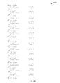
- the arbitration table is walked and respective counts for each port are loaded into a port counter. For example, if using the arbitration table as illustrated in FIG. 5 , walking the table (all 32 phases) would result in the following counts for each of the ports:
- a state machine may be used to walk the phase table and do the port counter loads. For example, all port counters could be cleared initially and then the state machine examines each phase entry as it walks the table and increments the respective port counter.
- the 32-Phase to Count State Machine completes walking through all the 32-entries the above 5-bit counters would hold their value and the arbitration logic could clear the Port Arbitration Table Status bit in the VC Resource 0 Status register indicating to software that the arbitration logic has completed loading in the table.
- the above mentioned counts p*_tc (* denoting range 1-7) hold their value until another load of the Port Arbitration Table occurs.
- the above counts are also transferred to their respective running count registers as shown below.
- ports 2 , 3 , 4 , and 7 are able to send traffic, for example, to an Upstream Port.
- the Upstream Port Arbitration State Machine would Round Robin through the Ports decrementing the current counts for the selected ports from which a packet is transferred.
- the decrementing of the respective port running counters as each port transaction is process is illustrated at 606 .
- a check is made to see if all the port running counters have reached 0 (zero), if they have not then the processing and decrementing continues at 606 , if the all running port counters are at 0, then at 604 they are reloaded with the respective port running counts 604 and the processing starts over 606 .
- port 7 in another scenario, say after a couple of transfers, port 7 's running count is zero and only ports 2 , 3 , and 4 have a non-zero running count. Now if the only valid candidate the arbitration logic receives from a Downstream Port requesting service is for a P7-to-P0 transfer, this would cause the running counts to be re-loaded and P7-to-P0 transfer would then be allowed to proceed. That is, the running counts only decrement if a valid transfer is selected and processed by the arbitration logic.
- this technique provides a non-blocking approach to transfers.
- FIG. 7 illustrates, generally at 700 , one embodiment of the invention showing major blocks.
- Egress port 0 710 may be connected to an upstream root device (not shown).
- Ingress ports 1 - 7 ( 711 - 717 respectively) may be connected to data sources.
- Port Arbitration Logic 702 controls which of the ports 1 - 7 ( 711 - 717 ) is connected to port 0 710 .
- Port arbitration (e.g. Port Arbitration Logic 702 ) is done based on the Phase Table and an arbitration scheme such as round robin (RR) or weighted round robin (WRR).
- RR round robin
- WRR weighted round robin
- FIG. 8 illustrates, generally at 800 , one embodiment of the invention showing major blocks and operations.
- an arbitration table 802 which is loaded by, for example, the operating system of a computer.
- the table is examined (walked) and respective port counts are put into port table count registers (Port 0 806 - 0 through Port n 806 - n respectively).
- the port table counts (Port 0 806 - 0 through Port n 806 - n respectively) are then copied to the respective port running counters (e.g. registers) (Port 0 810 - 0 through Port n 810 - n respectively).
- the Port Arbitration Logic 812 then uses these running counters ( 810 - 0 through 810 - n ) to arbitrate and allow ports 1 through n ( 820 - 1 through 820 - n ) to connect to port 0 ( 820 - 0 ) in this example.
- the port running counts 810 - 0 through 810 - n ) are reloaded 808 from the respective table counts ( 806 - 0 through 806 - n ).
- the port arbitration logic 812 continues to operate.
- the port running counts are decremented as soon as a TLP (Transaction Layer Packet) is initiated. For example if the last running port count is for port 1 and a TLP starts transferring then a reload of all the running counters occurs while the port 1 to port 0 TLP (e.g. in FIG. 8 ) is happening.
- the port arbitration logic e.g. 812 in FIG. 8 ) does not need to delay or stop. It may continue running at full speed.
- Port Arbitration Logic may access the port running count registers or counters in a variety of ways to perform the arbitration.
- a round robin may be used as well as more logic.
- FIG. 9 illustrates, generally at 900 , one embodiment of the invention.
- a WRR having 32 phases and 8 ports implementation e.g. FIG. 5
- Port 0 is a fixed egress port and ports 1 - 7 are ingress
- Port 1 count ( 902 ) has two transition paths to Port 2 count ( 908 ).
- the first path is Port 1 count is greater than zero ( 904 ), in which case the Port 1 count (at 902 ) is decremented and a Port 1 to Port 0 TLP transfer occurs.
- the second path is where Port 1 count equals zero ( 906 ), in which case the logic transitions to 908 directly.
- logic may be used to test, for example for Port 1 count and Port 2 count both being zero in which case a transition may be made directly from Port 1 to Port 3 , skipping Port 2 .
- FIG. 10 illustrates, generally at 1000 , one embodiment of the invention in flow chart form.
- a check is made to see if all port running counts are at zero. If all port running counts are at zero then at 1010 all the port running counters are reloaded (e.g. FIG. 8 , at 808 , 810 - 0 to 810 - n ) and processing continues at 1002 . If all port counts are not at zero at 1002 , then at 1004 a check is made to see if any ports with a respective running counter having a count greater than zero are requesting service (e.g. TLP ready to transfer) and if so then at 1006 the respective running count is decremented and the TLP is transferred and processing then continues at 1004 .
- TLP ready to transfer e.g. TLP ready to transfer
- FIG. 10 the embodiment is non-blocking. Additionally, one of skill in the art will understand that the logic of FIG. 10 may be placed into part of the arbitration logic, for example, it may be an embodiment for block 814 in FIG. 8 .
- FIG. 11 illustrates, generally at 1100 , another embodiment of the invention in flow chart form.
- a check is made to see if all port running counts are at zero. If all port running counts are at zero then at 1110 all the port running counters are reloaded (e.g. FIG. 8 , at 808 , 810 - 0 to 810 - n ) and processing continues at 1102 . If all port counts are not at zero at 1102 , then at 1104 a check is made to see if any ports with a respective running counter having a count greater than zero are requesting service (e.g.
- FIG. 11 is a non-blocking embodiment.
- One of skill in the art will appreciate that the embodiment as illustrated in FIG. 11 has different latency and weighting than a strict walking of a phase table.
- FIGS. 12A-F illustrates, generally at 1200 , one embodiment of the invention showing RTL (register transfer level) code.
- zzaybe has up to 8 ports means zzaybe may have 8 ports.
- xxnoc may have 1 to 7 means xxnoc may be 1, 2, 3, 4, 5, 6, or 7.
- the terms “respective”, “corresponding” or similar language shall be understood to relate to a similarly labeled entity.
- the phrase “wwecox ports 1 - 7 are coupled to corresponding (or respective) qqncx ports” or ““wwecox ports 1 - 7 are coupled to corresponding (or respective) qqncx ports 1 - 7 ” means that wwecox port 1 is coupled to qqncx port 1 , and wwecox port 2 is coupled to qqncx port 2 , and so on through wwecox port 7 is coupled to qqncx port 7 .
- This one to one relationship applies to ports, registers, etc.
- FIG. 1 illustrates a network environment 100 in which the techniques described may be applied.
- the network environment 100 has a network 102 that connects S servers 104 - 1 through 104 -S, and C clients 108 - 1 through 108 -C. More details are described below.
- FIG. 2 is a block diagram of a computer system 200 in which some embodiments of the invention may be used and which may be representative of use in any of the clients and/or servers shown in FIG. 1 , as well as, devices, clients, and servers in other Figures. More details are described below.
- FIG. 1 illustrates a network environment 100 in which the techniques described may be applied.
- the network environment 100 has a network 102 that connects S servers 104 - 1 through 104 -S, and C clients 108 - 1 through 108 -C.
- S servers 104 - 1 through 104 -S and C clients 108 - 1 through 108 -C are connected to each other via a network 102 , which may be, for example, a corporate based network.
- the network 102 might be or include one or more of: the Internet, a Local Area Network (LAN), Wide Area Network (WAN), satellite link, fiber network, cable network, or a combination of these and/or others.
- LAN Local Area Network
- WAN Wide Area Network
- satellite link fiber network
- cable network or a combination of these and/or others.
- the servers may represent, for example, disk storage systems alone or storage and computing resources. Likewise, the clients may have computing, storage, and viewing capabilities.
- the method and apparatus described herein may be applied to essentially any type of communicating means or device whether local or remote, such as a LAN, a WAN, a system bus, etc. Thus, the invention may find application at both the S servers 104 - 1 through 104 -S, and C clients 108 - 1 through 108 -C.
- FIG. 2 illustrates a computer system 200 in block diagram form, which may be representative of any of the clients and/or servers shown in FIG. 1 .
- the block diagram is a high level conceptual representation and may be implemented in a variety of ways and by various architectures.
- Bus system 202 interconnects a Central Processing Unit (CPU) 204 , Read Only Memory (ROM) 206 , Random Access Memory (RAM) 208 , storage 210 , display 220 , audio, 222 , keyboard 224 , pointer 226 , miscellaneous input/output (I/O) devices 228 , and communications 230 .
- CPU Central Processing Unit
- ROM Read Only Memory
- RAM Random Access Memory
- the bus system 202 may be for example, one or more of such buses as a system bus, Peripheral Component Interconnect (PCI), PCI Express (PCI-E, PCIe), Advanced Graphics Port (AGP), Small Computer System Interface (SCSI), Institute of Electrical and Electronics Engineers (IEEE) standard number 1394 (FireWire), Universal Serial Bus (USB), etc.
- the CPU 204 may be a single, multiple, or even a distributed computing resource.
- Storage 210 may be Compact Disc (CD), Digital Versatile Disk (DVD), hard disks (HD), optical disks, tape, flash, memory sticks, video recorders, etc.
- Display 220 might be, for example, an embodiment of the present invention.
- the computer system may include some, all, more, or a rearrangement of components in the block diagram.
- a thin client might consist of a wireless hand held device that lacks, for example, a traditional keyboard.
- An apparatus for performing the operations herein can implement the present invention.
- This apparatus may be specially constructed for the required purposes, or it may comprise a general-purpose computer, selectively activated or reconfigured by a computer program stored in the computer.
- a computer program may be stored in a computer readable storage medium, such as, but not limited to, any type of disk including floppy disks, hard disks, optical disks, compact disk-read only memories (CD-ROMs), and magnetic-optical disks, read-only memories (ROMs), random access memories (RAMs), electrically programmable read-only memories (EPROM)s, electrically erasable programmable read-only memories (EEPROMs), FLASH memories, magnetic or optical cards, etc., or any type of media suitable for storing electronic instructions either local to the computer or remote to the computer.
- ROMs read-only memories
- RAMs random access memories
- EPROM electrically programmable read-only memories
- EEPROMs electrically erasable programmable read-only memories
- the methods of the invention may be implemented using computer software. If written in a programming language conforming to a recognized standard, sequences of instructions designed to implement the methods can be compiled for execution on a variety of hardware platforms and for interface to a variety of operating systems.
- the present invention is not described with reference to any particular programming language. It will be appreciated that a variety of programming languages may be used to implement the teachings of the invention as described herein.
- a non-transitory machine-readable medium is understood to include any mechanism for storing or transmitting information in a form readable by a machine (e.g., a computer).
- a machine-readable medium includes read only memory (ROM); random access memory (RAM); magnetic disk storage media; optical storage media; flash memory devices;
- one embodiment or “an embodiment” or similar phrases means that the feature(s) being described are included in at least one embodiment of the invention. References to “one embodiment” in this description do not necessarily refer to the same embodiment; however, neither are such embodiments mutually exclusive. Nor does “one embodiment” imply that there is but a single embodiment of the invention. For example, a feature, structure, act, etc. described in “one embodiment” may also be included in other embodiments. Thus, the invention may include a variety of combinations and/or integrations of the embodiments described herein.
- the terms “comprising” and “containing” shall be understood to have a broad meaning similar to the term “including” and will be understood to be non-exhaustive and imply the inclusion of a stated integer or step or group of integers or steps but not the exclusion of any other integer or step or group of integers or steps. This definition also applies to variations on the terms “comprising” and containing” such as “comprise”, “comprises”; “contain” and contains”.
Abstract
Description
-
- the phase contains the Egress Port's Port Number, or
- the Ingress Port indicated by the phase does not contain any transaction for the VC.
The Port Arbitration Table Entry Size field in the Port VC Capability register determines the table entry size. The length of the table is determined by the Port Arbitration Select field as shown in Table 7-45.
When the Port Arbitration Table is used by the default Port Arbitration for the default VC, the default values for the table entries must contain at least one entry for each of the other PCI Express Ports of the device to ensure forward progress for the default VC for each Port. The table may contain RR or RR-like fair Port Arbitration for the default VC.
| | Count | ||
| Port |
| 1 | 0 | |
| |
14 | |
| |
7 | |
| |
6 | |
| |
0 | |
| |
0 | |
| |
5 | |
Claims (15)
Priority Applications (1)
| Application Number | Priority Date | Filing Date | Title |
|---|---|---|---|
| US11/854,495 US7787378B1 (en) | 2007-09-12 | 2007-09-12 | Method and apparatus for conversion of an arbitration table into count values to control the distribution of resources |
Applications Claiming Priority (1)
| Application Number | Priority Date | Filing Date | Title |
|---|---|---|---|
| US11/854,495 US7787378B1 (en) | 2007-09-12 | 2007-09-12 | Method and apparatus for conversion of an arbitration table into count values to control the distribution of resources |
Publications (1)
| Publication Number | Publication Date |
|---|---|
| US7787378B1 true US7787378B1 (en) | 2010-08-31 |
Family
ID=42646675
Family Applications (1)
| Application Number | Title | Priority Date | Filing Date |
|---|---|---|---|
| US11/854,495 Active 2028-06-26 US7787378B1 (en) | 2007-09-12 | 2007-09-12 | Method and apparatus for conversion of an arbitration table into count values to control the distribution of resources |
Country Status (1)
| Country | Link |
|---|---|
| US (1) | US7787378B1 (en) |
Cited By (1)
| Publication number | Priority date | Publication date | Assignee | Title |
|---|---|---|---|---|
| US20170270066A1 (en) * | 2016-03-17 | 2017-09-21 | International Business Machines Corporation | Self-moderating bus arbitration architecture |
Citations (1)
| Publication number | Priority date | Publication date | Assignee | Title |
|---|---|---|---|---|
| US20080151753A1 (en) * | 2006-12-20 | 2008-06-26 | Wynne John M | Method of improving over protocol-required scheduling tables while maintaining same |
-
2007
- 2007-09-12 US US11/854,495 patent/US7787378B1/en active Active
Patent Citations (1)
| Publication number | Priority date | Publication date | Assignee | Title |
|---|---|---|---|---|
| US20080151753A1 (en) * | 2006-12-20 | 2008-06-26 | Wynne John M | Method of improving over protocol-required scheduling tables while maintaining same |
Cited By (3)
| Publication number | Priority date | Publication date | Assignee | Title |
|---|---|---|---|---|
| US20170270066A1 (en) * | 2016-03-17 | 2017-09-21 | International Business Machines Corporation | Self-moderating bus arbitration architecture |
| US10303631B2 (en) * | 2016-03-17 | 2019-05-28 | International Business Machines Corporation | Self-moderating bus arbitration architecture |
| US10521381B2 (en) | 2016-03-17 | 2019-12-31 | International Business Machines Corporation | Self-moderating bus arbitration architecture |
Similar Documents
| Publication | Publication Date | Title |
|---|---|---|
| US9053058B2 (en) | QoS inband upgrade | |
| US6246256B1 (en) | Quantized queue length arbiter | |
| US7636367B1 (en) | Method and apparatus for overbooking on FIFO memory | |
| US6976106B2 (en) | Method and apparatus for speculative response arbitration to improve system latency | |
| US7197588B2 (en) | Interrupt scheme for an Input/Output device | |
| US5842025A (en) | Arbitration methods and apparatus | |
| US20130219131A1 (en) | Low access time indirect memory accesses | |
| US7844752B2 (en) | Method, apparatus and program storage device for enabling multiple asynchronous direct memory access task executions | |
| US9471398B2 (en) | Global lock contention predictor | |
| US8291136B2 (en) | Ring buffer | |
| US20130054856A1 (en) | Providing Adaptive Bandwidth Allocation For A Fixed Priority Arbiter | |
| JP4999925B2 (en) | Method and apparatus for performing arbitration | |
| US7532636B2 (en) | High bus bandwidth transfer using split data bus | |
| US7302691B2 (en) | Scalable low bandwidth multicast handling in mixed core systems | |
| US8527684B2 (en) | Closed loop dynamic interconnect bus allocation method and architecture for a multi layer SoC | |
| US7787378B1 (en) | Method and apparatus for conversion of an arbitration table into count values to control the distribution of resources | |
| US9280503B2 (en) | Round robin arbiter handling slow transaction sources and preventing block | |
| US8320392B1 (en) | Method and apparatus for programmable buffer with dynamic allocation to optimize system throughput with deadlock avoidance on switches | |
| US10664396B2 (en) | Systems, methods and apparatus for fabric delta merge operations to enhance NVMeoF stream writes | |
| US9082118B2 (en) | Transaction flow control using credit and token management | |
| US6336179B1 (en) | Dynamic scheduling mechanism for an asynchronous/isochronous integrated circuit interconnect bus | |
| US7231499B2 (en) | Prioritization of real time / non-real time memory requests from bus compliant devices | |
| US9280502B1 (en) | Minimal-cost pseudo-round-robin arbiter | |
| US11862289B2 (en) | Sum address memory decoded dual-read select register file | |
| CN115297169B (en) | Data processing method, device, electronic equipment and medium |
Legal Events
| Date | Code | Title | Description |
|---|---|---|---|
| AS | Assignment |
Owner name: INTEGRATED DEVICE TECHNOLOGY, INC., CALIFORNIA Free format text: ASSIGNMENT OF ASSIGNORS INTEREST;ASSIGNOR:LAKHIA, ALIASGAR;REEL/FRAME:019819/0297 Effective date: 20070910 |
|
| FEPP | Fee payment procedure |
Free format text: PAYOR NUMBER ASSIGNED (ORIGINAL EVENT CODE: ASPN); ENTITY STATUS OF PATENT OWNER: LARGE ENTITY |
|
| STCF | Information on status: patent grant |
Free format text: PATENTED CASE |
|
| AS | Assignment |
Owner name: INTEGRATED DEVICE TECHNOLOGY, INC., CALIFORNIA Free format text: ASSIGNMENT OF ASSIGNORS INTEREST;ASSIGNOR:PMC-SIERRA US, INC.;REEL/FRAME:030832/0604 Effective date: 20130712 |
|
| AS | Assignment |
Owner name: PMC-SIERRA US, INC., CALIFORNIA Free format text: CORRECTIVE ASSIGNMENT TO CORRECT THE CONVEYING AND RECEIVING PARTIES PREVIOUSLY RECORDED ON REEL 030832 FRAME 0604. ASSIGNOR(S) HEREBY CONFIRMS THE CONVEYING PARTY DATA: INTEGRATED DEVICE TECHNOLOGY, INC. TECEIVING: PMC-SIERRA US, INC;ASSIGNOR:INTEGRATED DEVICE TECHNOLOGY, INC.;REEL/FRAME:030919/0040 Effective date: 20130712 |
|
| AS | Assignment |
Owner name: BANK OF AMERICA, N.A., NORTH CAROLINA Free format text: SECURITY INTEREST IN PATENTS;ASSIGNORS:PMC-SIERRA, INC.;PMC-SIERRA US, INC.;WINTEGRA, INC.;REEL/FRAME:030947/0710 Effective date: 20130802 |
|
| FPAY | Fee payment |
Year of fee payment: 4 |
|
| AS | Assignment |
Owner name: PMC-SIERRA US, INC., CALIFORNIA Free format text: RELEASE BY SECURED PARTY;ASSIGNOR:BANK OF AMERICA, N.A.;REEL/FRAME:037675/0129 Effective date: 20160115 Owner name: WINTEGRA, INC., CALIFORNIA Free format text: RELEASE BY SECURED PARTY;ASSIGNOR:BANK OF AMERICA, N.A.;REEL/FRAME:037675/0129 Effective date: 20160115 Owner name: PMC-SIERRA, INC., CALIFORNIA Free format text: RELEASE BY SECURED PARTY;ASSIGNOR:BANK OF AMERICA, N.A.;REEL/FRAME:037675/0129 Effective date: 20160115 |
|
| AS | Assignment |
Owner name: MORGAN STANLEY SENIOR FUNDING, INC., NEW YORK Free format text: PATENT SECURITY AGREEMENT;ASSIGNORS:MICROSEMI STORAGE SOLUTIONS, INC. (F/K/A PMC-SIERRA, INC.);MICROSEMI STORAGE SOLUTIONS (U.S.), INC. (F/K/A PMC-SIERRA US, INC.);REEL/FRAME:037689/0719 Effective date: 20160115 |
|
| AS | Assignment |
Owner name: MICROSEMI STORAGE SOLUTIONS (US), INC., CALIFORNIA Free format text: ASSIGNMENT OF ASSIGNORS INTEREST;ASSIGNOR:PMC-SIERRA US, INC.;REEL/FRAME:038016/0493 Effective date: 20160115 |
|
| MAFP | Maintenance fee payment |
Free format text: PAYMENT OF MAINTENANCE FEE, 8TH YEAR, LARGE ENTITY (ORIGINAL EVENT CODE: M1552) Year of fee payment: 8 |
|
| AS | Assignment |
Owner name: MICROSEMI STORAGE SOLUTIONS, INC., CALIFORNIA Free format text: RELEASE BY SECURED PARTY;ASSIGNOR:MORGAN STANLEY SENIOR FUNDING, INC.;REEL/FRAME:046251/0271 Effective date: 20180529 Owner name: MICROSEMI STORAGE SOLUTIONS (U.S.), INC., CALIFORN Free format text: RELEASE BY SECURED PARTY;ASSIGNOR:MORGAN STANLEY SENIOR FUNDING, INC.;REEL/FRAME:046251/0271 Effective date: 20180529 |
|
| MAFP | Maintenance fee payment |
Free format text: PAYMENT OF MAINTENANCE FEE, 12TH YEAR, LARGE ENTITY (ORIGINAL EVENT CODE: M1553); ENTITY STATUS OF PATENT OWNER: LARGE ENTITY Year of fee payment: 12 |