US7782879B2 - Method and system for multi-layer signaling across multiple control networks - Google Patents
Method and system for multi-layer signaling across multiple control networks Download PDFInfo
- Publication number
- US7782879B2 US7782879B2 US11/428,098 US42809806A US7782879B2 US 7782879 B2 US7782879 B2 US 7782879B2 US 42809806 A US42809806 A US 42809806A US 7782879 B2 US7782879 B2 US 7782879B2
- Authority
- US
- United States
- Prior art keywords
- layer
- call
- controllers
- network
- ncc
- Prior art date
- Legal status (The legal status is an assumption and is not a legal conclusion. Google has not performed a legal analysis and makes no representation as to the accuracy of the status listed.)
- Active, expires
Links
- 230000011664 signaling Effects 0.000 title claims abstract description 66
- 238000000034 method Methods 0.000 title claims abstract description 31
- 238000004891 communication Methods 0.000 claims abstract description 12
- 230000004044 response Effects 0.000 claims description 6
- 238000005516 engineering process Methods 0.000 claims description 4
- 235000008694 Humulus lupulus Nutrition 0.000 claims description 3
- 238000004590 computer program Methods 0.000 claims description 2
- 239000000470 constituent Substances 0.000 claims description 2
- 239000010410 layer Substances 0.000 abstract description 248
- 239000011229 interlayer Substances 0.000 abstract description 18
- 230000006870 function Effects 0.000 description 17
- 230000007246 mechanism Effects 0.000 description 6
- 230000003287 optical effect Effects 0.000 description 6
- 238000013507 mapping Methods 0.000 description 5
- XRIWLEWQNCECEP-UHFFFAOYSA-N 3-methyl-3-nitrososulfanyl-2-(propanoylamino)butanoic acid Chemical compound CCC(=O)NC(C(O)=O)C(C)(C)SN=O XRIWLEWQNCECEP-UHFFFAOYSA-N 0.000 description 4
- VTYYLEPIZMXCLO-UHFFFAOYSA-L Calcium carbonate Chemical compound [Ca+2].[O-]C([O-])=O VTYYLEPIZMXCLO-UHFFFAOYSA-L 0.000 description 4
- 230000006978 adaptation Effects 0.000 description 4
- RGNPBRKPHBKNKX-UHFFFAOYSA-N hexaflumuron Chemical compound C1=C(Cl)C(OC(F)(F)C(F)F)=C(Cl)C=C1NC(=O)NC(=O)C1=C(F)C=CC=C1F RGNPBRKPHBKNKX-UHFFFAOYSA-N 0.000 description 3
- 108091034117 Oligonucleotide Proteins 0.000 description 2
- 230000005540 biological transmission Effects 0.000 description 2
- 230000006872 improvement Effects 0.000 description 2
- 238000013519 translation Methods 0.000 description 2
- 230000004075 alteration Effects 0.000 description 1
- 238000013459 approach Methods 0.000 description 1
- 230000009286 beneficial effect Effects 0.000 description 1
- 230000008901 benefit Effects 0.000 description 1
- 238000013461 design Methods 0.000 description 1
- 230000003993 interaction Effects 0.000 description 1
- 238000012986 modification Methods 0.000 description 1
- 230000004048 modification Effects 0.000 description 1
- 230000008569 process Effects 0.000 description 1
- 238000012552 review Methods 0.000 description 1
- 239000002356 single layer Substances 0.000 description 1
Images


Classifications
-
- H—ELECTRICITY
- H04—ELECTRIC COMMUNICATION TECHNIQUE
- H04Q—SELECTING
- H04Q3/00—Selecting arrangements
- H04Q3/0016—Arrangements providing connection between exchanges
- H04Q3/0025—Provisions for signalling
-
- H—ELECTRICITY
- H04—ELECTRIC COMMUNICATION TECHNIQUE
- H04Q—SELECTING
- H04Q3/00—Selecting arrangements
- H04Q3/0016—Arrangements providing connection between exchanges
- H04Q3/0029—Provisions for intelligent networking
Definitions
- the present invention relates generally to communication networks. More particularly, the present invention relates to call control in communication networks with multiple layers.
- Modern communication networks are characterized by a large number of interconnected networks each of which may implement any one or more of a variety of transport protocols (e.g. Ethernet, ATM, TCP/IP; SONET/SDH).
- transport protocols e.g. Ethernet, ATM, TCP/IP; SONET/SDH.
- adaptation services provided by the gateway servers facilitate transport of client data between the involved networks.
- ITU International Telecommunications Union
- G.805 The transport (bearer) plane has an architecture described in G.805—which involves transport layers, e.g.
- G.805 discusses how layers relate by multiplexing one layer into another (E.g., multiplexing multiple DSOs into a DS1, or according to the SDH or SONET hierarchy), in a process called adaptation.
- Two related transport plane layers are related (i.e., one is adapted into another) in a client-server relationship (e.g., 28 ⁇ 64 kb voice DS0 layers are multiplexed into a DS1).
- client-server relationship e.g., 28 ⁇ 64 kb voice DS0 layers are multiplexed into a DS1
- Such a relationship is recursive in nature as a first layer can be adapted into a second layer which in turn can be adapted into a third layer, etc.
- G.8080 for the control plane (Automatically Switched Optical Network—ASON); and Tele-Management Forum (TMF) model TMF608 for the management plane.
- ASON Automatically Switched Optical Network—ASON
- TMF Tele-Management Forum
- TMF814 is an interface specification of TMF that instantiates the TMF608 model.
- G.8080 defines two types of call controllers: calling/called party call controllers (CCCs); and network call controllers (NCCs).
- TMF814 provides an interface that uses the G.805 model of connections. The relationship between connections at different layers is known in the TMF814 interface. Thus it can be used to manage multi-layer connections across the network.
- Carrier transport networks typically use a Signaling Control Network (SCN) to allow call controllers to talk to each other.
- SCN Signaling Control Network
- An SCN is typically a separate network from the transport plane and is used to allow NCCs to communicate. This is often used for control plane signaling, or to allow management functions from existing SONET networks, which do not have control planes, to interact with NEs.
- each carrier uses its own SCN and each layer may use separate SCNs. Furthermore, even within a single carrier, there may be different divisions which control particular services, which each operate with some level of autonomy. This can lead to different domains within a single carrier, and consequently multiple SCNs within a single layer. Note that more than one carrier may be co-located due to access requirements and corresponding regulations, which can also produce multiple SCNs within a layer.
- Recommendation G.8080/Y.1304 [2] was that it was defined for a single-layered control plane. Recently, there have been proposed improvements to rectify this limitation in the Recommendation. This improvement added the capability for inter layer calls which preserves independence between control planes per layer.
- a proposal for a call control using a layered call model is described in United States Patent Application 20050074029, “Call control using a layered call model”, Apr. 7, 2005, which is assigned to the assignee of the present application, and which is hereby incorporated by reference.
- the first solution consists of embedding the first layer signaling in the second layer signaling. This leads to additional signaling on the server layer and the SCN at the server layer may need to be designed to support additional control traffic.
- a layer may need to carry embedded client layer information that may in turn carry embedded client layer information for the layer above. Since there is no bound on the number of layers, it may be difficult to design an SCN that will satisfy the requirements recursively.
- the second solution consists of performing independent signaling at each layer, as discussed in Optical Internetworking Forum contribution (OIF) 2005.088.07, “OIF Supercomm 2005 Demo Control Plane Protocol Specification”, October 2005 (hereafter referred to as the OIF 2005 demo), which is hereby incorporated by reference.
- OIF 2005 demo Optical Internetworking Forum contribution
- a single SCN was assumed to provide signaling connectivity between any call controller pair, regardless of layer.
- the solution used for the OIF 2005 demo consisted of signaling client layer SCN information at the server layer, allowing the client layer to setup a signaling adjacency and perform signaling directly at the client layer.
- aspects of the invention provide a method and system to setup a call in a multi-layer network using the interlayer aspect of the ASON architecture where there is a plurality of SCNs between domains within a layer and between layers.
- aspects of the invention enables an inter layer call to allow a client call to be transmitted at a server layer, even if there are multiple SCNs. Even though transmission occurs at the server layer, the network still needs a signaling path for control information at the client layer.
- NCCs with the ability to communicate with a paired NCC.
- NCCs with the ability to communicate with a paired NCC.
- a client NCC X which is associated with a server NCC Z, can also provide NCC Z with knowledge of client NCC Y which has a signaling link with NCC X.
- the system determines the intermediate NCCs needed for a signaling path between end nodes of a client layer.
- system can be recursive, as there can be multiple layers, with one layer acting as a server layer to a client layer above it, and also acting as a client layer to a server layer below it.
- An aspect of the invention provides a mechanism for determining the relay functions between the control entities at a client layer by its server layer.
- a call completed at a server layer gathers information about the corresponding control entities at the client layer, and returns this information to the client layer, which can then determine the routing between the necessary control entities at the client layer.
- an ordered list of first layer network controllers is generated at a second layer by using information about intermediate first layer network call controllers provided by associations of pairs of first and second layer network call controllers. This ordered list is then communicated to a first layer network controller, thus identifying a first layer signaling path.
- an aspect of the invention provides a method of call set up between first and second network call controllers in a first layer comprising: a) Establishing a call between said first and second network call controllers via a plurality of network call controllers in a second layer; and b) Generating an ordered list of network call controllers in said first layer which provide a signaling path between said first and second network controllers.
- this second step can include i) Generating an ordered list of first layer network call controllers at said second layer in response to said establishing step; and ii) Communicating said ordered list to aid first network call controller for establishing signaling between said first and second network call controllers in said first layer. This may be particularly beneficial when hops in said signaling path can cross different signaling control networks (SCNs).
- SCNs signaling control networks
- successive network call controllers at the boundary of SCNs form sets of network call controllers and wherein sets of network call controllers in a first layer are associated with boundary network call controllers in said second layer. These sets of network call controllers in the first layer form the constituents of said ordered list.
- the step of establishing the call comprises establishing call segments between successive network call controllers in the second layer, and the step of generating the ordered list comprises adding a set of network call controllers in said first layer to said ordered list for each call segment spanning a mapped boundary network call controller in said second layer.
- a further aspect provides a computer program product containing computer instructions stored in a machine readable medium, which when executed by a processor, instructs a network to set up between first and second network call controllers in a first layer comprising: a) instructions for establishing a call between said first and second network call controllers via a plurality of network call controllers in a second layer; b) instructions for generating an ordered list of network call controllers in said first layer which provide a signaling path between said first and second network controllers which include: i) instructions for generating an ordered list of first layer network call controllers at said second layer in response to said establishing step; and ii) instructions for communicating said ordered list to aid first network call controller for establishing signaling between said first and second network call controllers in said first layer.
- the control plane can be distributed. Accordingly, it should be appreciated that such instructions can be executed on more than one processor.
- Another aspect of the invention includes a network of nodes operable to execute such instructions.
- FIG. 1 is a schematic drawing which provides an example network.
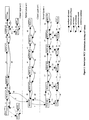
- FIG. 2 illustrates a call sequence between the source and destination clients shown in FIG. 1 , according to an embodiment of the invention.
- FIG. 3 illustrates an example case where a loop could be created and a way to optimize the method to remove repeated sections.
- the present invention provides a method and system for making a multilayered call in a network that includes a plurality of subnetworks.
- Embodiments of the invention may be represented as a software product stored in a machine-readable medium (also referred to as a computer-readable medium, a processor-readable medium, or a computer usable medium having a computer readable program code embodied therein).
- the machine-readable medium may be any suitable tangible medium, including magnetic, optical, or electrical storage medium including a diskette, compact disk read only memory (CD-ROM), memory device (volatile or non-volatile), or similar storage mechanism.
- the machine-readable medium may contain various sets of instructions, code sequences, configuration information, or other data, which, when executed, cause a processor to perform steps in a method according to an embodiment of the invention.
- Those of ordinary skill in the art will appreciate that other instructions and operations necessary to implement the described invention may also be stored on the machine-readable medium.
- Software running from the machine readable medium may interface with circuitry to perform the described tasks.
- FIG. 1 provides an example network that will be used as a reference model for illustrating the solution. It shows a multi-layer network where there are multiple SCNs per layer. The SCN boundaries could correspond to ASON domains, for example. Three layers are shown but there are no theoretical limits on the number of layers the network could support.
- layer n acts as a server layer to client layers above it.
- the top layer (which is the layer which wishes to initiate a call) is layer n+2.
- FIG. 1 shows transport constructs including a subnetwork and access point which is adapted into a server layer, which is further adapted into another server layer.
- FIG. 1 also shows corresponding control plane constructs, CCCs and NCCs, which are related to signaling. So in FIG. 1 , the CCCs and NCCs boxes at the top of the figure are control plane constructs for that client layer.
- FIG. 1 illustrates the mechanisms and functions needed to illustrate the example, without explicitly showing the nodes themselves.
- the functions are carried out by various nodes in the network. It should be noted that there does not need to be a 1-to-1 correspondence between functions (e.g., NCC) and nodes, as a node can perform more than one function, and certain functions can be distributed. Thus the circles and squares are not necessarily nodes.
- a Node is the location where a collection of functions exist. So each construct represents an entity executed by a processor—which can be at different location than as shown. From a routing perspective, each layer possesses knowledge of the resources, for example, subnetworks, links and pseudo-nodes, to complete a connection.
- Layer n+2 is aware of the resources between b and c that enable a path between CCC source and CCC dest . These resources are provided by a server layer that is layer n+1. Similarly, layer n+1 views resources between e and f that enable a path between them.
- the top layer, client layer n+2 comprises a source CCC source associated with access point a, and a destination client CCC dest associated with access point d.
- the top layer also comprises network call controllers NCC-A and NCC-D and a few Network Call Controller Gateways (NCCG), NCCG-B and NCCG-C, and signaling networks SCN 1 -SCN 5 .
- An NCCG is a function that performs forwarding of call related signaling messages without interactions with a subnetwork. It should be understood that NCCG-B and NCCG-C can be full NCCs. However, as there is no bearer plane, the full functionality of an NCC is not required, as typically only signaling (control information) needs to be passed between NCCGs. We therefore introduce a reduced function NCC, which we identify as an NCCG.
- the term NCC includes both a full function (conventional) NCC, and a reduced function NCC (NCCG).
- the top layer also includes a subnetwork 100 transporting data flow between connection point a and connection point b, and a subnetwork 180 transporting data flow between connection point c and connection point d.
- the middle layer acts as the server layer (n+1) to the top layer (client layer n+2) and as the client layer (n+1) to the bottom server layer n.
- FIG. 1 does not illustrate any subnetworks in the middle layer, as none are required.
- the middle layer comprises network call controllers NCC-E, NCCG-F, NCCG-G, NCCG-H, NCCG-I and NCC-J, and associated signaling networks SCN 6 -SCN 10 .
- the bottom layer, server layer n includes connection points g, h, i, j, k and l.
- Subnetworks 110 , 120 and 130 allow communication between connection points g and h, i and j and k and l respectively.
- Link connections allow communication between j and k and between h and i.
- the bottom layer also comprises network call controllers NCC-K, NCC-M, NCC-N, NCC-O, and NCC-P, and signaling networks SCN 11 -SCN 15 .
- access point a desires to make a call to access point d but the CC domains do not have actual resources at layer n+2 to do so other than subnetworks 100 and 180 .
- the call controllers on their boundaries are aware that a server layer can provide a connection over which a layer n+2 connection can be mapped. This awareness could be provided by a representation of the server layer connectivity by a pseudo node to the routing function at layer n+2. This representation is described in Optical Internetworking Forum contribution 2006.105.00, “Interlayer Architecture for UNI 2.0 and ENNI 2.0”, May 2006.
- the CC domains do not have actual resources, so the call uses the transport layer n, which does have the actual resources in that layer to complete the call.
- the routing function at each layer provides transport layer paths to access points and the pseudo node enables access points to be reported by routing as reachable when actual transport layer resources do not exist.
- NCC A does not have resources at layer n+2 to complete the call from a to d, it requests a server layer NCC, in this case NCC E, to complete the call.
- NCC E requests a server layer NCC, in this case NCC E, to complete the call.
- Such a request is referred to as an inter layer call.
- NCC E also does not have the necessary resources, it makes an inter layer call to NCC K in layer n.
- Layer n has the resources to complete the call, so NCC K commences a path to NCC P via each successive NCC (L, M, N, O).
- NCC E knows that e and f need to connect—but does not know how to reach NCC J, which is on a different SCN (where the addressing may be different). Furthermore, NCC A does not know how to reach NCC D, as NCC D is on different SCN.
- FIGS. 1 and 2 illustrate an embodiment of the invention that enables an interlayer call to allow a client call to be transmitted at a server layer, even if there are multiple SCNs. Even though transmission occurs at the server layer, the network still needs a signaling path for control information at the client layer.
- NCC Network-to-Network Interface
- FIGS. 1 and 2 illustrate an embodiment of the invention that enables an interlayer call to allow a client call to be transmitted at a server layer, even if there are multiple SCNs. Even though transmission occurs at the server layer, the network still needs a signaling path for control information at the client layer.
- NCC to include conventional NCCs and reduced function NCCGs.
- each NCC could be provisioned with knowledge of every other NCC. However, in complex real world networks, this could prove an onerous task for a network operator.
- NCCs associations between pairs of NCCs where the first NCC of the pair is in a client layer and the second is in a server layer to that client layer.
- Each NCC is typically at an SCN boundary.
- Such an association provides an NCC in one layer with knowledge of the paired NCC in the other layer.
- Such an association can also provide knowledge of horizontal network call controller relationships (i.e., NCCs with the ability to communicate with a paired NCC).
- NCCs with the ability to communicate with a paired NCC.
- a client NCC X which is associated with a server NCC Z, can also provide NCC Z with knowledge of client NCC Y which has a signaling link with NCC X.
- ⁇ NCCG-G, NCC-M> and ⁇ NCCG-I, NCC-N> form two such pairs.
- the knowledge of intermediate NCCs i.e., NCCs which do not belong to an associated pair
- the server layer NCC-M and/or NCC-N the following information needs to be entered:
- the following client layer NCCG-G can reach the following client layer NCCG-I through ⁇ NCCG-G, NCCG-H, NCCG-I>.
- the signalling process makes note of the intermediate NCCs via the provisioned knowledge.
- the signaling process has identified a corresponding sequence of NCCs and NCCGs in the client layer, which can be used for control plane signaling at that client layer.
- server layer n completes connection from K to P, it has learned that the layer above needs to communicate through the ordered list of network call controllers NCC-E, NCCG-F, NCCG-G, NCCG-H, NCCG-I, and NCC-J.
- NCC K provides this generated ordered list to the NCC which made the inter layer call (NCC E), thus informing NCC E that it needs to traverse NCCs F, G, H, and I in order to get to NCC J.
- NCC E accordingly establishes a signaling adjacency to NCC-J through NCCG-F, NCCG-G, NCCG-H and NCCG-I using the ordered list provided by NCC-K.
- the system learns of the corresponding ordered list of call controllers needed in the layer above. Therefore when NCC-E replies to the interlayer call request from NCC-A, it communicates the generated ordered list of NCC-A, NCCG-B, NCCG-C, and NCC-D to the client layer above.
- NCCs at a server layer are configured with a set of ordered lists of NCCs that need to be used to cross SCN boundaries at a corresponding client layer.
- Each provisioned ordered list includes 0, 1 or more NCCs and is specified with respect to another NCC.
- NCC J is provisioned with knowledge of NCC-D and this association is illustrated as mapping 200 .
- mapping 200 is illustrated in the example illustrated in FIG.
- the ⁇ NCC-C, NCC-I> and ⁇ NCC-D, NCC-J> pairs are configured so that when signalling establishes the NCC-I to NCC-J signalling segment that crosses SCN- 10 , it becomes known that the sequence NCC-C and NCC-D, is needed in the corresponding client layer to support the interlayer call and this sequence will cross SCN- 4 .
- NCC M is configured with a set of ordered list of client NCCs with respect to selected server NCCs K and N.
- the list for client layer n+1 for NCC K contains E-F-G (associations 250 / 240 ) and the list for client layer n+1 for NCC N contains G-H-I (associations 240 / 230 ).
- FIG. 1 illustrates many potential relationships between the SCNs at two different layers. For example, it is possible that the SCN boundaries are aligned between two layers. This is the case of SCN 4 and SCN 10 where a 1:1 relationship is illustrated between line 220 linking NCCG C with NCCG I and line 200 linking NCC D and NCC J. It is also possible that there is one SCN at one layer and multiple SCNs at the other layer. This is the case of SCN 10 and SCNs 14 - 15 where we have a 1:N relationship, which is illustrated in FIG. 1 between the solid line 230 linking NCCG-I with NCC-N and line 210 linking NCC-J and NCC-P.
- FIG. 1 illustrates many potential relationships between the SCNs at two different layers. For example, it is possible that the SCN boundaries are aligned between two layers. This is the case of SCN 4 and SCN 10 where a 1:1 relationship is illustrated between line 220 linking NCCG C with NCCG I and line 200 linking NCC D and NCC J. It is also possible that
- N:1 also illustrates the N:1 case, as can be seen with SCNs 8 - 9 and SCN 13 , which is illustrated between line 240 linking NCCG-G and NCC-M and line 230 linking NCCG-I and NCC-N.
- the last case is when there are multiple SCNs at one layer mapping to multiple SCNs at another layer. For example 2 SCNs at the client layer (in FIG. 1 , SCN 2 and 3 ) are associated with 4 SCNs at the server layer (in FIG. 1 , SCN 6 - 9 ), as can be seen between lines 260 , linking NCC-A to NCC-E, and 220 , linking NCCG-C to NCCG-I.
- NCC-E and NCC-J could contain information about their respective pairs ⁇ NCC-A, NCC-E> and ⁇ NCC-D, NCC-J> and all intermediate NCC/NCCGs that need to be traversed at the client layer, i.e. NCC-A, NCCG-B, NCCG-C, NCC-D.
- NCC-A, NCCG-B, NCCG-C, NCC-D the network is divided into a manageable number of server/client NCC associations that need to be mapped and for which intermediate NCC/NCCGs need to be provisioned.
- the layer n+1 knows that when attempting to connect from E to I, there is an SCN mapping that identifies the need to go through A, B, and C in the client layer above corresponding to the ⁇ NCC-A, NCC-E> pair (line 260 ) and ⁇ NCCG-C, NCC-I> pair (line 220 ). Similarly, both I and J know that C and D can communicate directly with each other.
- a boundary network controller is a NCC at the boundary of a SCN. More generally, in order to establish a client layer signaling path, successive network call controllers at the boundary of SCNs form sets of network call controllers in a first layer, which are associated with boundary network call controllers in said second layer. At least some of these associations between sets of network controllers in said first layer and boundary network controllers in said second layer are provisioned in advance. These associations can be provisioned in advance by appropriate mappings as shown or they can be established through a naming convention of the network call controllers across multiple layers.
- FIG. 2 An example of the call sequence between a source and destination client in layer n+2 is illustrated in FIG. 2 .
- FIG. 2 illustrates the message flows according to an embodiment of the invention, for a call for the example illustrated in FIG. 1 .
- Note FIG. 2 is similar to FIG. 1 , but it also illustrates the Connection Controllers (CCsrc and CC A at the source and CC D and CC dest at the destination), and a numbered sequence of events for establishing an interlayer call, according to an embodiment of the invention.
- CCsrc and CC A at the source and CC D and CC dest at the destination
- NCC-A can not further complete the call (at the top layer) as there are no resources available at layer n+2 between connection points b and c. Therefore NCC-A makes an interlayer call (dotted line) 6 to NCC-E in a server layer (n+1). NCC-E subsequently realizes that it also can not complete the call in its layer as there are no resources available at layer n+1 between connection points e and f. Consequently NCC-E makes an interlayer call (dotted line) 7 to NCC-K in a server layer n.
- the steps that occur in the bottom layer (n) represent, for the most part, a traditional call set-up, according to the protocol/standard of the lower layer.
- the NCCs with the provisioned SCN mappings (K, M, N, and P) in addition gather the list of intermediate NCC/NCCGs between the various client/server NCC pairs.
- the lower layer determines the middle layer sequence of NCCs/NCCGs E, F, G, H, and I, and communicates this ordered set of NCCs/NCCGs to its client layer (n+1), as shown at step 38 .
- the lower (server) layer establishes connections to complete the call at its layer, it generates an ordered list of network controllers at the layer above it (client layer) needed for signaling at that (client) layer.
- NCC-E learns about the path needed to setup a signaling adjacency to NCC-J. It must go through NCC-F, G, H and I. NCC-E can setup a signaling adjacency in layer n+1 from NCC-E to NCC-J once the ordered list is communicated to NCC-E from the server layer.
- the system similarly determines the corresponding list of controllers in the top layer (n+2) as the sequence of NCCs/NCCGs NCC-E, NCC-F, NCC-G, NCC-H, NCC-I, NCC-J. is traversed in layer n+1.
- layer n+1 uses a ordered list (passed to it from the layer below) to know how to traverse the signaling networks and at the same time, collects sufficient information to allow the client layer to traverse its signaling networks.
- Call setup is initiated by CCC source and results in a link connection being established across the first subnetwork 100 in steps 1 - 4 .
- address resolution returns an SNPP corresponding to the destination Transport Network Address (TNA) at the UNI to the destination client CCC dest .
- TAA Transport Network Address
- This SNPP is learned from the Routing Controller that has the higher level view of the layer.
- Path computation returns a path that indicates that the destination SNPP is reachable through a pseudo-node.
- the presence of the pseudo-node indicates that there are no client resources available for a connection, and that a server layer is needed.
- the interlayer address resolution function is called using the client layer SNPPs on either side of the links into the pseudo-node.
- Source and destination TNAs in the server layer (layer n+1 in FIG. 1 ) are returned, and a call is made to NCC-E with those TNAs in layer n+1 at step 6 .
- NCC-E determines whether a new call should be created or if an existing one can be used.
- the source and destination TNAs in layer n+1 are resolved into SNPPs.
- Path computation returns a path that indicates the destination SNPP is reachable through a pseudo-node.
- the presence of the pseudo-node indicates that there are no resources available at that layer and a server layer is needed.
- the interlayer address resolution function is called using the layer n+1 SNPPs on either side of the links into the pseudo-node.
- Source and destination TNAs in the server layer n are returned and a call is made to NCC-K with those TNAs at step 7 . Note that the procedures are recursive and NCC-E performs the exact same steps as NCC-A. Since the procedures are recursive, there is no bound on the number of adjacent layers.
- NCC-E determines that an existing call can be used, it signals along the existing path (steps 39 to 48 ) in order to bind the requesting client layer n+2 to the server layer n+1 and retrieving the ordered list of call controllers to be used to cross the SCN boundaries at the client layer. In this case, steps 8 to 37 would have already been performed and layer n does not need to be involved again. Skip to step 49 .
- NCC-K determines whether a new call is setup or if an existing one can be used.
- the call controllers NCC-K, NCC-M, NCC-N and NCC-P record information about the client call controller to be used to cross SCN boundaries at the client layer.
- NCC-K and NCC-M can record that NCC-G can be reached from NCC-E by going through NCC-F, based on a provisioned list of client layer intermediate NCCs between NCC-E and NCCG-F available at NCC-K and NCC-M for the following pairs ⁇ NCC-E, NCC-K> and ⁇ NCCG-G, NCC M>.
- the ordered list of client call controllers to traverse to cross client layer n+1 SCN boundaries consists of NCC-E, NCCG-F, NCCG-G, NCCG-H, NCCG-I, NCC-J.
- NCC-K determines that an existing call can be used, it signals along the existing path of call controllers in order to bind the requesting client layer to the server layer and retrieve the ordered list of call controllers to be used to cross the E-NNI at the client layer SCN boundary (steps 12 - 37 ). Accordingly, when an existing call can be used, the step of Establishing a call between said first and second network call controllers via a plurality of network call controllers in a second layer can comprise re-using existing call segments of another call.
- connection points CPs
- NCC-K connection points
- NCC-E the ordered list of NCCs is examined and the first NCC is removed from the ordered list and translated into an SCN identifier for NCCG-F.
- a call request is sent hop by hop.
- This lookup and translation of NCCs is performed at NCCG-F, NCCG-G, NCCG-H, NCCG-I and NCC-J and call confirmed messages are returned on the reverse direction.
- the ordered list of client layer n+2 NCC is collected and recorded. For example, NCC-E or NCC-I record that the NCC-A can reach NCCG-C through NCC-B.
- the final ordered list of NCC looks like this: NCC-A, NCCG-B, NCCG-C, NCC-D.
- Step 49 At the completion of the server layer call n+1, a pair of CPs is handed back in step 49 together with an ordered list of NCCs/NCCGs to use to cross the SCNs at the client layer.
- the client/server adaptation is associated to these CPs. This effectively provides the connection corresponding to the call segment between NCC-E and NCC-J.
- NCC-A the ordered list of NCCs is examined and the first NCC is removed from the ordered list and translated into an SCN identifier for NCC-B.
- a call request is sent hop by hop. This lookup and translation of NCCs is also performed at NCC-C.
- NCC-D call and connection control signaling continues to CCC dest (steps 53 - 58 ). This is followed by call confirmed messages (steps 59 - 62 ) following the same signaling path in the reverse direction through NCC-C and NCC-B in order to finally reach NCC-A and CCC source .
- Embodiments of the invention can be applied to a “carrier's carrier” (e.g., one business/division of a carrier provides a service using the carrier's transport network (which may be run by a different business/division)).
- carrier's carrier e.g., one business/division of a carrier provides a service using the carrier's transport network (which may be run by a different business/division)
- the first and second layers are from the same transport layer technology.
- FIG. 3 illustrates an example case where a loop could be created, and a way to optimize the method to remove repeated sections.
- an association between NCCs J and L and NCCs A and I is provisioned on NCC Js and L together with an ordered list to reach NCC I from NCC A consisting of NCC G and NCC H.
- NCCs J and M an association to NCCs A and F is provisioned together with an ordered list to reach NCC F from NCC A consisting of NCC B, C, D and E.
- NCCs L and M an association to NCCs I and F is provisioned together with an ordered list to reach NCC F from NCC I consisting of NCCs I, H, G, A, B, C, D, E, F.
- the NCC pair J and L will collect the ordered list of NCCs A-G-H-I and the NCC pair L and M will collect the following ordered list of NCCs I-H-G-A-B-C-D-E-F.
- the concatenated ordered list A-G-H-I-I-H-G-A-B-C-D-E-F contains a loop that can be eliminated by any NCC that has visibility to the loop to produce a loop free ordered list of A-B-C-D-E-F.
Abstract
Description
- SCN—Signaling Control Network
- NCC—Network Call Controller
- NCCG—Network Call Controller Gateway
- CC—Connection Controller
- CCC—Client Call Controller
- UNI—User to Network Interface
- E-NNI—External Network to Network Interface
- SNPP—Subnetwork Point Pool
- OIF—Optical Internetworking Forum
Claims (20)
Priority Applications (1)
| Application Number | Priority Date | Filing Date | Title |
|---|---|---|---|
| US11/428,098 US7782879B2 (en) | 2006-03-30 | 2006-06-30 | Method and system for multi-layer signaling across multiple control networks |
Applications Claiming Priority (2)
| Application Number | Priority Date | Filing Date | Title |
|---|---|---|---|
| US78723406P | 2006-03-30 | 2006-03-30 | |
| US11/428,098 US7782879B2 (en) | 2006-03-30 | 2006-06-30 | Method and system for multi-layer signaling across multiple control networks |
Publications (2)
| Publication Number | Publication Date |
|---|---|
| US20070230505A1 US20070230505A1 (en) | 2007-10-04 |
| US7782879B2 true US7782879B2 (en) | 2010-08-24 |
Family
ID=38563017
Family Applications (1)
| Application Number | Title | Priority Date | Filing Date |
|---|---|---|---|
| US11/428,098 Active 2029-06-24 US7782879B2 (en) | 2006-03-30 | 2006-06-30 | Method and system for multi-layer signaling across multiple control networks |
Country Status (4)
| Country | Link |
|---|---|
| US (1) | US7782879B2 (en) |
| EP (1) | EP2008428B1 (en) |
| CA (1) | CA2648130C (en) |
| WO (1) | WO2007112534A1 (en) |
Cited By (5)
| Publication number | Priority date | Publication date | Assignee | Title |
|---|---|---|---|---|
| US8553707B2 (en) | 2011-03-01 | 2013-10-08 | Ciena Corporation | Administrative boundaries in single or multiple domain optical networks |
| US10069570B2 (en) | 2016-01-27 | 2018-09-04 | Ciena Corporation | Multi-layer modem reclamation systems and methods |
| US10374964B2 (en) | 2016-03-07 | 2019-08-06 | Huawei Technologies Co., Ltd. | Control channel compression upon congestion detection |
| US10491501B2 (en) | 2016-02-08 | 2019-11-26 | Ciena Corporation | Traffic-adaptive network control systems and methods |
| US11277330B1 (en) | 2020-10-21 | 2022-03-15 | Ciena Corporation | Multi-domain network path computation with minimal model and data sharing between domains |
Citations (7)
| Publication number | Priority date | Publication date | Assignee | Title |
|---|---|---|---|---|
| US5570084A (en) | 1994-06-28 | 1996-10-29 | Metricom, Inc. | Method of loose source routing over disparate network types in a packet communication network |
| CA2244564A1 (en) | 1997-12-10 | 1999-06-10 | Northern Telecom Limited | Capability modeling using templates in network management system |
| US20040114924A1 (en) * | 2002-09-20 | 2004-06-17 | Marc Holness | System and method for managing an optical networking service |
| US20050074029A1 (en) * | 2003-10-03 | 2005-04-07 | Nortel Networks Limited | Call control using a layered call model |
| US6999998B2 (en) | 2001-10-04 | 2006-02-14 | Hewlett-Packard Development Company, L.P. | Shared memory coupling of network infrastructure devices |
| US20080310417A1 (en) * | 2004-04-06 | 2008-12-18 | Nortel Networks Limited | Differential forwarding in address-based carrier networks |
| US7477843B1 (en) * | 2003-09-05 | 2009-01-13 | Nortel Networks Limited | Method of and system for routing in a photonic network |
-
2006
- 2006-06-30 US US11/428,098 patent/US7782879B2/en active Active
- 2006-06-30 WO PCT/CA2006/001090 patent/WO2007112534A1/en active Application Filing
- 2006-06-30 CA CA2648130A patent/CA2648130C/en active Active
- 2006-06-30 EP EP06752862A patent/EP2008428B1/en active Active
Patent Citations (7)
| Publication number | Priority date | Publication date | Assignee | Title |
|---|---|---|---|---|
| US5570084A (en) | 1994-06-28 | 1996-10-29 | Metricom, Inc. | Method of loose source routing over disparate network types in a packet communication network |
| CA2244564A1 (en) | 1997-12-10 | 1999-06-10 | Northern Telecom Limited | Capability modeling using templates in network management system |
| US6999998B2 (en) | 2001-10-04 | 2006-02-14 | Hewlett-Packard Development Company, L.P. | Shared memory coupling of network infrastructure devices |
| US20040114924A1 (en) * | 2002-09-20 | 2004-06-17 | Marc Holness | System and method for managing an optical networking service |
| US7477843B1 (en) * | 2003-09-05 | 2009-01-13 | Nortel Networks Limited | Method of and system for routing in a photonic network |
| US20050074029A1 (en) * | 2003-10-03 | 2005-04-07 | Nortel Networks Limited | Call control using a layered call model |
| US20080310417A1 (en) * | 2004-04-06 | 2008-12-18 | Nortel Networks Limited | Differential forwarding in address-based carrier networks |
Non-Patent Citations (4)
| Title |
|---|
| ITU-T Recommendation G.8080/Y.1304 (2006), "Draft Revised Recommendation G.8080/Y.1304 (for consent)", Geneva, Feb. 6-17, 2006. |
| Optical Internet Working Forum contribution oif2004.477.05, "OIF UNI 2.0 Ethernet Architectural Discussion", Jan. 17, 2006, pp. 1-18. |
| Optical Internet Working Forum contribution oif2006.105.00, "Interlayer Architecture for UNI 2.0 and ENNI 2.0", May 2006. |
| Optical Internetworking Forum contribution oif2005.088.07, "OIF Supercomm 2005 Demo Control Place Protocal Specification", Oct. 18, 2005. |
Cited By (5)
| Publication number | Priority date | Publication date | Assignee | Title |
|---|---|---|---|---|
| US8553707B2 (en) | 2011-03-01 | 2013-10-08 | Ciena Corporation | Administrative boundaries in single or multiple domain optical networks |
| US10069570B2 (en) | 2016-01-27 | 2018-09-04 | Ciena Corporation | Multi-layer modem reclamation systems and methods |
| US10491501B2 (en) | 2016-02-08 | 2019-11-26 | Ciena Corporation | Traffic-adaptive network control systems and methods |
| US10374964B2 (en) | 2016-03-07 | 2019-08-06 | Huawei Technologies Co., Ltd. | Control channel compression upon congestion detection |
| US11277330B1 (en) | 2020-10-21 | 2022-03-15 | Ciena Corporation | Multi-domain network path computation with minimal model and data sharing between domains |
Also Published As
| Publication number | Publication date |
|---|---|
| CA2648130C (en) | 2013-10-15 |
| EP2008428A1 (en) | 2008-12-31 |
| CA2648130A1 (en) | 2007-10-11 |
| EP2008428A4 (en) | 2012-01-25 |
| US20070230505A1 (en) | 2007-10-04 |
| WO2007112534A1 (en) | 2007-10-11 |
| EP2008428B1 (en) | 2012-11-28 |
Similar Documents
| Publication | Publication Date | Title |
|---|---|---|
| US8503305B2 (en) | Automatic signaling method and device for telecommunication services | |
| EP1201100B1 (en) | Method and apparatus for fast reroute in a connection-oriented network | |
| US7164679B2 (en) | Scalable abstraction of topology across domain boundaries | |
| US7852863B2 (en) | System and methods for connections using automatically switched optical network control planes | |
| CA2313904C (en) | Supporting multiple services in label switched networks | |
| EP1659729B1 (en) | A method for choosing the transmission path of the real-time traffic data | |
| US7710872B2 (en) | Technique for enabling traffic engineering on CE-CE paths across a provider network | |
| US9559944B2 (en) | Method and related apparatus for establishing link-diverse traffic paths in a telecommunications network | |
| US6985447B2 (en) | Label switched traffic routing and signaling in a label switched communication packet network | |
| US8300625B2 (en) | Call control using a layered call model | |
| CN101471853A (en) | Route calculation method, unit and system | |
| US9112638B2 (en) | OSS support for control plane technology | |
| US7782879B2 (en) | Method and system for multi-layer signaling across multiple control networks | |
| US20090103533A1 (en) | Method, system and node apparatus for establishing identifier mapping relationship | |
| CN104429030A (en) | Signaling co-routed and non co-routed lsps of bidirectional packet te tunnel | |
| EP1653639B1 (en) | Signalling routing apparatus and method in optical network | |
| CN101160929A (en) | Client layer link automatically discovering method and apparatus | |
| EP2096801B1 (en) | A united route query method in the automatic switched optical network | |
| EP2988451A1 (en) | Method and system for mapping different layouts | |
| EP1185069A2 (en) | Method and system for providing anonymity in an IP telephony network | |
| Jajszczyk | Control plane for optical networks: The ASON approach | |
| CN106549798B (en) | A method of network, which is constructed, in IP communication network manages bus | |
| Jajszczyk | The ASON approach to the control plane for optical networks | |
| WO2012084626A1 (en) | Method for inter-domain communications | |
| FR2822615A1 (en) | Call routing system for heterogeneous networks uses topology servers optimizes routing |
Legal Events
| Date | Code | Title | Description |
|---|---|---|---|
| AS | Assignment |
Owner name: NORTEL NETWORKS LIMITED, CANADA Free format text: ASSIGNMENT OF ASSIGNORS INTEREST;ASSIGNORS:ROCH, MS. EVELYNE;SHEW, MR. STEPHEN;REEL/FRAME:017862/0894 Effective date: 20060630 |
|
| FEPP | Fee payment procedure |
Free format text: PAYOR NUMBER ASSIGNED (ORIGINAL EVENT CODE: ASPN); ENTITY STATUS OF PATENT OWNER: LARGE ENTITY |
|
| AS | Assignment |
Owner name: CIENA LUXEMBOURG S.A.R.L.,LUXEMBOURG Free format text: ASSIGNMENT OF ASSIGNORS INTEREST;ASSIGNOR:NORTEL NETWORKS LIMITED;REEL/FRAME:024213/0653 Effective date: 20100319 Owner name: CIENA LUXEMBOURG S.A.R.L., LUXEMBOURG Free format text: ASSIGNMENT OF ASSIGNORS INTEREST;ASSIGNOR:NORTEL NETWORKS LIMITED;REEL/FRAME:024213/0653 Effective date: 20100319 |
|
| AS | Assignment |
Owner name: CIENA CORPORATION,MARYLAND Free format text: ASSIGNMENT OF ASSIGNORS INTEREST;ASSIGNOR:CIENA LUXEMBOURG S.A.R.L.;REEL/FRAME:024252/0060 Effective date: 20100319 Owner name: CIENA CORPORATION, MARYLAND Free format text: ASSIGNMENT OF ASSIGNORS INTEREST;ASSIGNOR:CIENA LUXEMBOURG S.A.R.L.;REEL/FRAME:024252/0060 Effective date: 20100319 |
|
| STCF | Information on status: patent grant |
Free format text: PATENTED CASE |
|
| FPAY | Fee payment |
Year of fee payment: 4 |
|
| AS | Assignment |
Owner name: DEUTSCHE BANK AG NEW YORK BRANCH, NEW YORK Free format text: SECURITY INTEREST;ASSIGNOR:CIENA CORPORATION;REEL/FRAME:033329/0417 Effective date: 20140715 |
|
| AS | Assignment |
Owner name: BANK OF AMERICA, N.A., AS ADMINISTRATIVE AGENT, NO Free format text: PATENT SECURITY AGREEMENT;ASSIGNOR:CIENA CORPORATION;REEL/FRAME:033347/0260 Effective date: 20140715 |
|
| FEPP | Fee payment procedure |
Free format text: PAYOR NUMBER ASSIGNED (ORIGINAL EVENT CODE: ASPN); ENTITY STATUS OF PATENT OWNER: LARGE ENTITY Free format text: PAYER NUMBER DE-ASSIGNED (ORIGINAL EVENT CODE: RMPN); ENTITY STATUS OF PATENT OWNER: LARGE ENTITY |
|
| MAFP | Maintenance fee payment |
Free format text: PAYMENT OF MAINTENANCE FEE, 8TH YEAR, LARGE ENTITY (ORIGINAL EVENT CODE: M1552) Year of fee payment: 8 |
|
| AS | Assignment |
Owner name: CIENA CORPORATION, MARYLAND Free format text: RELEASE BY SECURED PARTY;ASSIGNOR:DEUTSCHE BANK AG NEW YORK BRANCH;REEL/FRAME:050938/0389 Effective date: 20191028 |
|
| AS | Assignment |
Owner name: BANK OF AMERICA, N.A., AS COLLATERAL AGENT, ILLINO Free format text: PATENT SECURITY AGREEMENT;ASSIGNOR:CIENA CORPORATION;REEL/FRAME:050969/0001 Effective date: 20191028 |
|
| MAFP | Maintenance fee payment |
Free format text: PAYMENT OF MAINTENANCE FEE, 12TH YEAR, LARGE ENTITY (ORIGINAL EVENT CODE: M1553); ENTITY STATUS OF PATENT OWNER: LARGE ENTITY Year of fee payment: 12 |
|
| AS | Assignment |
Owner name: CIENA CORPORATION, MARYLAND Free format text: RELEASE BY SECURED PARTY;ASSIGNOR:BANK OF AMERICA, N.A.;REEL/FRAME:065630/0232 Effective date: 20231024 |