US7782730B2 - Optical-pickup-adjustment optical disk, method of adjusting optical pickup device, and method of producing optical pickup device - Google Patents
Optical-pickup-adjustment optical disk, method of adjusting optical pickup device, and method of producing optical pickup device Download PDFInfo
- Publication number
- US7782730B2 US7782730B2 US12/071,131 US7113108A US7782730B2 US 7782730 B2 US7782730 B2 US 7782730B2 US 7113108 A US7113108 A US 7113108A US 7782730 B2 US7782730 B2 US 7782730B2
- Authority
- US
- United States
- Prior art keywords
- optical
- adjustment
- pickup
- information recording
- recording layer
- Prior art date
- Legal status (The legal status is an assumption and is not a legal conclusion. Google has not performed a legal analysis and makes no representation as to the accuracy of the status listed.)
- Expired - Fee Related, expires
Links
Images


Classifications
-
- G—PHYSICS
- G11—INFORMATION STORAGE
- G11B—INFORMATION STORAGE BASED ON RELATIVE MOVEMENT BETWEEN RECORD CARRIER AND TRANSDUCER
- G11B7/00—Recording or reproducing by optical means, e.g. recording using a thermal beam of optical radiation by modifying optical properties or the physical structure, reproducing using an optical beam at lower power by sensing optical properties; Record carriers therefor
- G11B7/12—Heads, e.g. forming of the optical beam spot or modulation of the optical beam
- G11B7/22—Apparatus or processes for the manufacture of optical heads, e.g. assembly
-
- G—PHYSICS
- G11—INFORMATION STORAGE
- G11B—INFORMATION STORAGE BASED ON RELATIVE MOVEMENT BETWEEN RECORD CARRIER AND TRANSDUCER
- G11B7/00—Recording or reproducing by optical means, e.g. recording using a thermal beam of optical radiation by modifying optical properties or the physical structure, reproducing using an optical beam at lower power by sensing optical properties; Record carriers therefor
- G11B7/12—Heads, e.g. forming of the optical beam spot or modulation of the optical beam
- G11B7/135—Means for guiding the beam from the source to the record carrier or from the record carrier to the detector
- G11B7/1372—Lenses
- G11B7/1376—Collimator lenses
-
- G—PHYSICS
- G11—INFORMATION STORAGE
- G11B—INFORMATION STORAGE BASED ON RELATIVE MOVEMENT BETWEEN RECORD CARRIER AND TRANSDUCER
- G11B7/00—Recording or reproducing by optical means, e.g. recording using a thermal beam of optical radiation by modifying optical properties or the physical structure, reproducing using an optical beam at lower power by sensing optical properties; Record carriers therefor
- G11B7/12—Heads, e.g. forming of the optical beam spot or modulation of the optical beam
- G11B7/135—Means for guiding the beam from the source to the record carrier or from the record carrier to the detector
- G11B7/1392—Means for controlling the beam wavefront, e.g. for correction of aberration
- G11B7/13925—Means for controlling the beam wavefront, e.g. for correction of aberration active, e.g. controlled by electrical or mechanical means
Definitions
- the present invention relates to an optical-pickup-adjustment optical disk used when an optical pickup device of an optical disk apparatus is adjusted, a method of adjusting an optical pickup device using the optical-pickup-adjustment optical disk, and a method of producing an optical pickup device using the method of adjusting an optical pickup device.
- a compact disc (CD), in or from which information is recorded or reproduced using a red laser beam having a center wavelength of 0.78 ⁇ m, and a digital versatile disc (DVD), in or from which information is recorded or reproduced using a red laser beam having a center wavelength of 0.65 ⁇ m, are put into practical use as optical disks.
- a “blue laser optical disk” such as a High-Definition DVD (HD-DVD) and a Blu-ray disc, in or from which information is recorded or reproduced using a blue laser beam having a center wavelength of 0.405 ⁇ m, is started to be in a practical use.
- a multilayered optical disk including a plurality of information recording layers is standardized in the DVD standard or the Blu-ray disc standard in order to implement higher density recording.
- an optical disk includes a transparent protective substrate on a side of laser beam incidence
- the protective substrate of a multilayer optical disk has different thicknesses in a region of a shallow information recording layer which is near the surface of the protective substrate and another region of a deep information recording layer which is far from the surface of the protective substrate.
- the Blu-ray disc standard prescribes that a distance between a shallow layer near the surface and a deep layer far from the surface is 25 ⁇ m, a thickness of the protective substrate in a region of the shallow layer is 75 ⁇ m (an average value), and a thickness of the protective substrate in a region of the deep layer is 100 ⁇ m (an average value).
- an optical system including a lens and a light detector is designed in such a way that the spherical aberration of an optical pickup device becomes the smallest.
- an optical pickup device compatible with a multilayer optical disk needs to have a function of adjusting the spherical aberration by itself.
- an optical pickup device that can adjust the spherical aberration by moving a collimator lens along an optical axis for converting a laser beam ejected from a semiconductor laser to a substantially parallel light beam (e.g., see Patent Document 1).
- Patent Document 1 is Japanese Patent Application Kokai (Laid-Open) Publication No. 2005-327395 (page 7, FIG. 2).
- the conventional optical pickup device has a problem that a detection signal output from the light detector varies due to the movement of the collimator lens.
- An object of the present invention is to provide an optical-pickup-adjustment optical disk that makes it possible to adopt an adjustment method, which can suppress an influence of the displacement of the collimator lens in the different direction from the direction of the optical axis on the detection signal of the light detector within a permissible range.
- another object of the present invention is to provide a method of adjusting an optical pickup device, which can suppress an influence of the displacement of the collimator lens in the different direction from the direction of the optical axis on the detection signal of the light detector within a permissible range, and a method of producing an optical pickup device using the method of adjusting an optical pickup device.
- an optical-pickup-adjustment optical disk is used for adjusting an optical pickup device, wherein the optical pickup device irradiates an optical disk comprising a plurality of information recording layers formed on a side of an inside surface of a transparent protective substrate with a laser beam, thereby applying the laser beam through the transparent protective substrate to any of the plurality of information recording layers to detect the laser beam reflected from the information recording layer, to which the laser beam is applied, and an optical disk, in or from which information is recorded or reproduced by the optical pickup device, is prescribed by an optical disk standard, which prescribes a maximum-depth information recording layer which is a layer having a maximum depth from an outer surface of the protective substrate, and a minimum-depth information recording layer which is a layer having a minimum depth, which is shallower than the maximum depth, from the outer surface of the protective substrate.
- the optical-pickup-adjustment optical disk includes a transparent protective substrate; and an optical-pickup-adjustment middle-depth information recording layer formed on a side of an inside surface of the transparent protective substrate, the optical-pickup-adjustment middle-depth information recording layer being formed to have a middle depth which is a center of the maximum depth of the maximum-depth information recording layer prescribed by the optical disk standard and the minimum depth of the minimum-depth information recording layer prescribed by the optical disk standard.
- a method of adjusting an optical pickup device uses an adjustment device including a disk drive means for rotating an optical disk, and a light detector adjustment means for adjusting a position of a light detector of the optical pickup device on the basis of a detection signal output from the light detector, and the above-described optical-pickup-adjustment optical disk loaded on the adjustment device.
- the method includes the steps of: rotating the optical-pickup-adjustment optical disk, by the disk drive means of the adjustment device; irradiating the optical-pickup-adjustment middle-depth information recording layer of the optical-pickup-adjustment optical disk through the protective substrate with a laser beam, and detecting the laser beam reflected from the optical-pickup-adjustment middle-depth information recording layer; and adjusting the position of the light detector of the optical pickup device on the basis of the detection result of the reflected laser beam.
- a method of adjusting an optical pickup device uses an adjustment device including a disk drive means for rotating an optical disk, a movement means for changing a relative position of the disk drive means to the optical disk, and a light detector adjustment means for adjusting a position of a light detector of the optical pickup device on the basis of a detection signal output from the light detector, and the above described optical-pickup-adjustment optical disk loaded on the adjustment device.
- the method includes the steps of: rotating the optical-pickup-adjustment optical disk, by the disk drive means of the adjustment device; changing the relative position between the optical pickup device and the optical-pickup-adjustment optical disk, by the movement means; irradiating the optical-pickup-adjustment middle-depth information recording layer of the optical-pickup-adjustment optical disk through the protective substrate with a laser beam, and detecting the laser beam reflected from the optical-pickup-adjustment middle-depth information recording layer; adjusting the position of the light detector of the optical pickup device on the basis of the detection result of the laser beam reflected from the optical-pickup-adjustment middle-depth information recording layer, by the light detector adjustment means of the adjustment device; changing a relative position between the optical pickup device and the optical-pickup-adjustment optical disk, by the movement means of the adjustment device, irradiating the optical-pickup-adjustment maximum-depth information recording layer of the optical-pickup-adjustment optical disk through the protective
- a method of producing an optical pickup device according to the present invention uses the above described method of adjusting an optical pickup device.
- the present invention By adjusting an optical pickup device using the optical-pickup-adjustment optical disk according to the present invention, an influence of the displacement of the collimator lens in the different direction from the direction of the optical axis on the detection signal of the light detector can be suppressed within a permissible range. Therefore, the present invention has an effect of improving detection accuracy of a signal recorded in an information recording layer.
- the present invention has an effect of improving detection accuracy of a signal recorded in an information recording layer.
- FIG. 1 is a diagram schematically showing a cross-sectional shape of an optical-pickup-adjustment optical disk according to the first embodiment of the present invention, a plan view of an optical pickup device, to which a method of adjusting an optical pickup device according to the first embodiment is applied, and structure of an adjustment device used for performing the method of adjusting an optical pickup device according to the first embodiment or the method of producing an optical pickup device using the method of adjusting an optical pickup device according to the first embodiment;
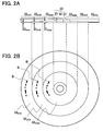
- FIG. 2A is a schematic cross-sectional view showing structure of the optical-pickup-adjustment optical disk according to the first embodiment
- FIG. 2B is a schematic plan view of the optical-pickup-adjustment optical disk according to the first embodiment when viewed from underside in FIG. 2A ;
- FIG. 3 is a diagram schematically showing a cross-sectional shape of the optical-pickup-adjustment optical disk according to the first embodiment of the present invention, and a plan view of the optical pickup device, to which the adjustment method using a middle-depth information recording layer of the optical-pickup-adjustment optical disk is applied;
- FIG. 4A shows a shape of a photosensitive surface of a light detector of the optical pickup device according to the first embodiment and an irradiation position of a laser beam
- FIG. 4B shows a focus error signal characteristic in the case of FIG. 4A
- FIG. 4C shows the shape of the photosensitive surface of the light detector of the optical pickup device according to the first embodiment and an irradiation position of a laser beam
- FIG. 4D shows a focus error signal characteristic in the case of FIG. 4C ;
- FIG. 5 is a diagram schematically showing a cross-sectional shape of the optical-pickup-adjustment optical disk according to the first embodiment of the present invention, and a plan view of the optical pickup device, to which a test using a maximum-depth information recording layer of the optical-pickup-adjustment optical disk is applied;
- FIG. 6 is a diagram schematically showing a cross-sectional shape of the optical-pickup-adjustment optical disk according to the first embodiment of the present invention, and a plan view of the optical pickup device, to which a test using a minimum-depth information recording layer of the optical-pickup-adjustment optical disk is applied;
- FIG. 7 is a diagram showing a shape of the photosensitive surface of the light detector of the optical pickup device according to the first embodiment and irradiation positions of a laser beam when a collimator lens moves;
- FIG. 8 is a flowchart schematically showing the method of adjusting an optical pickup device according to the first embodiment
- FIG. 9 is a cross-sectional view schematically showing an optical-pickup-adjustment optical disk according to the second embodiment of the present invention.
- FIG. 10 is a cross-sectional view schematically showing an optical-pickup-adjustment optical disk according to the third embodiment of the present invention.
- FIG. 1 is a diagram schematically showing a cross-sectional shape of an optical-pickup-adjustment optical disk 30 according to the first embodiment of the present invention, a plan shape of an optical pickup device 10 applied to an adjustment method according to the first embodiment, and structure of an adjustment device 20 used for performing a method of adjusting an optical pickup device according to the first embodiment.
- an optical pickup device is constructed or assembled as shown in FIG. 1 and then the constructed optical pickup device 10 is connected to an adjustment device 20 , and an optical-pickup-adjustment optical disk 30 is loaded on a spindle motor 28 of the adjustment device 20 .
- the optical pickup device 10 is in conformity with the multilayer optical disk standard.
- the optical pickup device 10 irradiates an optical disk including the multilayer information recording layers formed on a side of an inner surface of a transparent protective substrate with a laser beam advancing in the same direction through the protective substrate, and detects the laser beam reflected from any of the multilayer information recording layers.
- the optical disk standard for an optical disk in or from which a signal is recorded or reproduced by the optical pickup device 10 , prescribes at least a maximum-depth information recording layer having a maximum depth, which is a distance from an outer surface of the protective substrate to the maximum-depth information recording layer, and a minimum-depth information recording layer having a minimum depth, which is a distance from an outer surface of the protective substrate to the minimum-depth information recording layer.
- the optical disk standard for an optical disk, in or from which a signal is recorded or reproduced by the optical pickup device 10 prescribes another information recording layer or layers in addition to the maximum-depth information recording layer and the minimum-depth information recording layer, that is, prescribes three or more information recording layers.
- the optical pickup device 10 includes a semiconductor laser 11 which emits a laser beam L 1 , a beam splitter 12 , a collimator lens optical system 13 , an object lens 14 , a cylindrical lens 15 , and a light detector 16 , as its main constituent elements.
- the collimator lens optical system 13 includes a collimator lens 131 , a lens holder 132 which holds the collimator lens 131 , guide shafts 133 which support the lens holder 132 so as to be able to be moved in a direction of an arrow D A , a motor 134 , and a screw shaft 135 which engages with a screw hole of the lens holder 132 and is coupled to a shaft of the motor 134 .
- the lens holder 132 , the guide shaft 133 , the motor 134 , and the screw shaft 135 form a collimator lens movement mechanism for causing the collimator lens 131 to move in a direction of an arrow D A substantially the same direction as a direction of the optical axis (hereinafter also referred to as “an optical axis of an object lens”) AX of the optical system including the elements of the semiconductor laser 11 to the object lens 14 .
- the screw shaft 135 is rotated by the motor 134 , the lens holder 132 slides along the guide shaft 133 in a direction of an arrow D A .
- a laser beam L 1 emitted from the semiconductor laser 11 passes through the beam splitter 12 to enter the collimator lens 131 .
- a laser beam L 1 is converted into the approximately parallel light beam by the collimator lens 131 and enters the object lens 14 to be focused in the optical-pickup-adjustment optical disk 30 .
- a laser beam L 2 reflected by the optical-pickup-adjustment optical disk 30 advances in a reverse direction, passes through the object lens 14 and the collimator lens 131 , is reflected by the beam splitter 12 , passes through the cylindrical lens 15 , and then impinges on the light detector 16 .
- the adjustment device 20 includes a reproduction signal detection circuit 21 which detects a reproduction signal from a signal output from the light detector 16 ; a control signal detection circuit 22 which detects a control signal from a signal output from the light detector 16 ; a signal correction circuit 23 which receives a reproduction signal output from the reproduction signal detection circuit 21 ; a light detector adjustment circuit 24 a which receives the reproduction signal output from the reproduction signal detection circuit 21 and a control signal output from the control signal detection circuit 22 and generates an adjustment signal; and a light detector adjustment mechanism 24 b which receives the adjustment signal output from the light detector adjustment circuit 24 a and includes, for example, a stepping motor and other components.
- the light detector adjustment mechanism 24 b is connected to a position adjustment mechanism (shown by the broken line) associated with the light detector 16 , and is adjusted in accordance with the adjustment signal output from the light detector adjustment circuit 24 a to adjust a position of the light detector 16 .
- the adjustment device 20 includes a lens movement circuit 25 which receives a signal output from the signal correction circuit 23 and outputs a lens movement signal to the motor 134 of the optical pickup device 10 ; a layer selection signal generator 26 ; a spindle motor movement circuit 27 a ; a spindle motor movement mechanism 27 b which operates on the basis of a signal output from the spindle motor movement circuit 27 a ; and a spindle motor 28 which rotates the optical disk put on the spindle motor movement mechanism 27 b .
- the signal output from the lens movement circuit 25 is input to the motor 134 of the optical pickup device 10 .
- the layer selection signal generator 26 outputs a signal relating to a selected layer of the optical-pickup-adjustment optical disk 30 generated by a system controller, not shown in the figure, to the lens movement circuit 25 and the spindle motor movement circuit 27 a , for example.
- a signal output from the spindle motor movement circuit 27 a is input to the spindle motor movement mechanism 27 b , and the spindle motor movement mechanism 27 b can move the spindle motor 28 in a direction of an arrow D B parallel to a radial direction of the optical-pickup-adjustment optical disk 30 .
- FIG. 2A is a schematic cross-sectional view showing structure of the optical-pickup-adjustment optical disk according to the first embodiment
- FIG. 2B is a schematic plan view of the optical-pickup-adjustment optical disk according to the first embodiment when viewed from underside in FIG. 2A .
- the optical-pickup-adjustment optical disk 30 includes a transparent protective substrate 31 , an information recording layer 32 formed on a side of an inner surface of the protective substrate 31 , and a protective layer 33 covering the information recording layer 32 .
- the information recording layer 32 includes an optical-pickup-adjustment maximum-depth information recording layer having a depth D max which is the same as that of the maximum-depth information recording layer prescribed by the optical disk standard; an optical-pickup-adjustment minimum-depth information recording layer 32 min having a depth D min which is the same as that of the minimum-depth information recording layer prescribed by the optical disk standard; and an optical-pickup-adjustment middle-depth information recording layer 32 mid having a depth D mid which is a middle of the depth D max of the maximum-depth information recording layer 32 max prescribed by the optical disk standard and the depth D min of the minimum-depth information recording layer 32 min prescribed by the optical disk standard.
- a depth of an information recording layer is equivalent to a thickness of the protective substrate 31 , namely, a distance from an outer surface of the protective substrate 31 to the information recording layer.
- each component of the optical-pickup-adjustment optical disk such as the information recording layers is formed in conformity with any of the various kinds of the optical disk (e.g., CD, DVD, HD-DVD, or Blu-ray disc) standards, and therefore formed by substantially the same structure and materials as the corresponding optical disk.
- the optical-pickup-adjustment maximum-depth information recording layer 32 max , the optical-pickup-adjustment middle-depth information recording layer 32 mid , and the optical-pickup-adjustment minimum-depth information recording layer 32 min are arranged in a radial direction from a side of a center of the optical-pickup-adjustment optical disk 30 toward outside.
- An optical-pickup-adjustment signal S (e.g., pits) used for adjusting an optical pickup device 10 are recorded in the optical-pickup-adjustment maximum-depth information recording layer 32 max , the optical-pickup-adjustment middle-depth information recording layer 32 mid , and the optical-pickup-adjustment minimum-depth information recording layer 32 min .
- FIGS. 2A and 2B show three different depths of the information recording layers, the optical-pickup-adjustment optical disk may have another information recording layer other than the above-mentioned three information recording layers having different depths.
- the arrangement of the information recording layers is not limited to an example shown in FIGS. 2A and 2B .
- the optical pickup device 10 to be adjusted is connected to the adjustment device 20 .
- the optical-pickup-adjustment optical disk 30 is loaded in the adjustment device 20 .
- a state after the loading is shown in FIG. 1 .
- the optical-pickup-adjustment middle-depth information recording layer 32 mid of the optical-pickup-adjustment optical disk 30 is selected in accordance with the layer selection signal output from the layer selection signal generator 26 , and then the spindle motor movement mechanism 27 b moves the optical-pickup-adjustment optical disk 30 in accordance with a signal output from the spindle motor movement circuit 27 a in such a way that the object lens 14 faces the optical-pickup-adjustment middle-depth information recording layer 32 mid of the optical-pickup-adjustment optical disk 30 .
- the spindle motor 28 rotates the optical-pickup-adjustment optical disk 30 .
- the optical pickup device 10 causes the motor 134 of the collimator lens optical system 13 to operate in accordance with an instruction output from the layer selection signal generator 26 , thereby moving the collimator lens 131 in a direction of an optical axis to a position corresponding to a depth of the optical-pickup-adjustment middle-depth information recording layer 32 mid , that is, the thickness D mid of the protective substrate 31 (P mid in FIG. 3 described below).
- the semiconductor laser 11 emits a laser beam L 1
- the light detector 16 receives the laser beam L 2 reflected from the middle-depth information recording layer 32 mid of the optical-pickup-adjustment optical disk 30 .
- the detection optical system for the reflected laser beam L 2 adopts a focus detection method based on the known astigmatism scheme using the cylindrical lens 15 .
- the light detector 16 outputs an electrical signal having intensity in accordance with the received laser beam L 2 to the reproduction signal detection circuit 21 and the control signal detection circuit 22 .
- the reproduction signal detection circuit 21 and the control signal detection circuit 22 detect a control signal such as the reproduction signal and the focus error signal, the light detector adjustment circuit 24 a calculates an optimum position of the light detector 16 , which realizes an optimum positional relationship between the reflected laser beam L 2 and the light detector 16 , and then the light detector adjustment mechanism 24 b operates so as to move the light detector 16 to an optimum position.
- quality of the reproduction signal is adjusted by adjusting the optical aberration in order to obtain more improvement of quality of the reproduction signal as follows.
- the signal correction circuit 23 analyzes quality of the reproduction signal output from the reproduction signal detection circuit 21 to output a result of the analysis to the lens movement mechanism 25 , and the lens movement mechanism 25 causes the collimator lens 131 to move in a direction of an arrow D A parallel to the movement axis 136 so as to obtain the highest quality of the reproduction signal.
- FIG. 1 indicates a case where the movement axis 136 of the collimator lens 131 coincides with the optical axis AX of the object lens 14 , there is a little deviation between them as shown in FIG. 3 described below.
- the motor 134 of the collimator lens optical system 13 is driven in accordance with a signal output from the lens movement circuit 25 , the screw shaft 135 rotates in accordance with operation of the motor 134 , the lens holder 132 moves along the guide shaft 133 in a direction of an arrow D A , and therefore the collimator lens 131 is adjusted so as to move the optimum position in view of aberration correction.
- the position adjustment of the light detector 16 is performed using the optical-pickup-adjustment middle-depth information recording layer 32 mid of the optical-pickup-adjustment optical disk 30 .
- the position adjustment of the light detector 16 can be performed using any information recording layer of the optical-pickup-adjustment optical disk 30 without any problems.
- quality of the control signal such as a reproduction signal and a focus error signal is checked using the optical-pickup-adjustment maximum-depth information recording layer 32 max and the optical-pickup-adjustment minimum-depth information recording layer 32 min of the optical-pickup-adjustment optical disk 30 .
- the collimator lens 131 is moved in a direction of an arrow D A along the movement axis 136 in such a way that the highest quality of the reproduction signal is obtained for each of the optical-pickup-adjustment maximum-depth information recording layer 32 max and the optical-pickup-adjustment minimum-depth information recording layer 32 min .
- the collimator lens 131 moves away from the object lens 14 (a case shown in FIG. 5 described below).
- the thickness of the protective substrate is small in a region of the optical-pickup-adjustment minimum-depth information recording layer 32 min , when the optical-pickup-adjustment minimum-depth information recording layer 32 min is used for position adjustment, the collimator lens 131 moves toward the object lens 14 (a case shown in FIG. 6 described below).
- FIG. 3 is a diagram schematically showing a plan view of the optical pickup device, to which the adjustment method using the optical-pickup-adjustment middle-depth information recording layer 32 mid of the optical-pickup-adjustment optical disk 30 is applied.
- FIG. 3 does not show the adjustment device 20 shown in FIG. 1
- the optical pickup device 10 is connected to the adjustment device 20 in a similar manner to the case shown in FIG. 1 .
- FIG. 3 shows a case where the collimator lens optical system 13 of the optical pickup device 10 is inclined with respect to an ideal arrangement.
- Such inclination or deviation of parallelism is influenced by the play between the lens holder 132 and the guide shaft 133 .
- This inclination of the movement axis 136 of the collimator lens 131 with respect to the optical axis AX leads to variation of a direction of an arrow D C between a position P max which is a position of the collimator lens 131 suitable for the depth D max of the optical-pickup-adjustment maximum-depth information recording layer 32 max (the thickness of the protective substrate 31 of the optical-pickup-adjustment maximum-depth information recording layer 32 max ) and a position P min which is a position of the collimator lens 131 suitable for the depth D min of the optical-pickup-adjustment minimum-depth information recording layer 32 min (the thickness of the protective substrate 31 of the optical-pickup-adjustment minimum-depth information recording layer 32 min ).
- FIG. 4A shows a shape of a photosensitive surface 10 a of the light detector of the optical pickup device according to the first embodiment and an irradiation position of a laser beam
- FIG. 4B shows a focus error signal characteristic in the case of FIG. 4A
- FIG. 4C shows the shape of the photosensitive surface 10 a of the light detector of the optical pickup device according to the first embodiment and an irradiation position of a laser beam
- FIG. 4D shows a focus error signal characteristic in the case of FIG. 4C
- FIGS. 4A and 4B show a case where the position adjustment of the light detector 16 is performed when the movement axis 136 of the collimator lens 131 coincides with the optical axis AX.
- FIG. 4C and 4D show a case where the collimator lens 131 is moved from a position of FIG. 4A so as to be suitable for a thickness of another protective substrate while accompanying the variation of a direction of an arrow D C perpendicular to the optical axis AX.
- the photosensitive surface 10 a of the light detector 16 is divided into four square photosensitive areas (a two-by-two matrix) so as to make it possible to perform the focus error detection based on the astigmatism scheme.
- the divided four photosensitive areas are assigned ‘A’ to ‘D’ respectively, intensities of the detection signals output from the divided four photosensitive areas are also indicated by A to D respectively in the following description.
- FIG. 1 shows that the photosensitive surface 10 a of the light detector 16 is divided into four square photosensitive areas (a two-by-two matrix) so as to make it possible to perform the focus error detection based on the astigmatism scheme.
- the focus error signal includes an offset component ‘d’, a focus error corresponding to the offset component ‘d’ occurs, and when amount of the focus error becomes large, the focus error interferes with the recording or reproducing of information.
- FIG. 5 is a diagram showing a cross-sectional shape of the optical-pickup-adjustment optical disk 30 and a plan view showing a position of the collimator lens 131 in the first embodiment of the present invention, when the adjustment device 20 selects the optical-pickup-adjustment maximum-depth information recording layer 32 max formed on the protective substrate having a thickness D max , which corresponds to the deepest layer of an optical disk having two layers prescribed by the optical disk standard. Further, FIG.
- FIG. 6 is a diagram showing a cross-sectional shape of the optical-pickup-adjustment optical disk 30 and a plan view showing a position of the collimator lens 131 in the first embodiment of the present invention, when the adjustment device 20 selects the optical-pickup-adjustment minimum-depth information recording layer 32 min formed on the protective substrate having a thickness D min , which corresponds to the shallowest layer of an optical disk having two layers prescribed by the optical disk standard.
- the collimator lens 131 is moved to the position P max in FIG. 5 , and is moved to the position P min in FIG. 6 . As shown in FIG. 3 , the position P max and the position P min are positioned on opposite sides with respect to the position P mid of the collimator lens 131 when the optical-pickup-adjustment middle-depth information recording layer 32 mid is selected.
- an amount of displacement of the collimator lens 131 in a direction perpendicular to the optical axis AX resulting from the movement of the collimator lens 131 from the position P mid to the position P max or from the position P mid to the position P min is approximately half of an amount of displacement of the collimator lens 131 in a direction perpendicular to the optical axis AX resulting from the movement of the collimator lens 131 from the position P max to the position P min .
- FIG. 7 is a diagram showing a shape of the photosensitive surface 10 a of the light detector 10 of the optical pickup device according to the first embodiment and irradiation positions of a laser beam L 1 when the collimator lens moves.
- L max denotes a position of distribution of the laser beam L 1 when the light detector 16 is adjusted under the condition that the collimator lens 131 is at the position P max .
- L max and L min denote positions of distribution of the laser beam L 1 when the light detector 16 is adjusted under the condition that the collimator lens 131 is at the position P max and the position P min respectively. Since directions of displacement of distribution of the laser beam L 1 under the condition that the collimator lens 131 is at the position P max or position P min , are opposite to each other, an amount of displacement becomes approximately half for the above-described reason.
- the above-described method of adjusting an optical pickup device of the first embodiment will be described while comparing it with the conventional method of adjusting. Since the conventional optical-pickup-adjustment optical disk includes only an information recording layer or layers having a depth or depths prescribed by the optical disk standard, the position of the light detector is adjusted after the selection of any of the information recording layers having depths prescribed with the optical disk standard. Therefore, when the collimator lens 131 is moved after the selection of the other information recording layer having a different depth that was not selected in the previous adjustment, there is a problem that the irradiation position of the laser beam L 2 impinging on the light detector 16 is largely deviated from a center of the photosensitive surface 10 a , as shown in FIGS. 4C and 4D .
- the optical-pickup-adjustment optical disk includes an optical-pickup-adjustment middle-depth information recording layer 32 mid having a middle depth of the maximum depth D max of the optical-pickup-adjustment maximum-depth information recording layer 32 max and the minimum depth D min of the optical-pickup-adjustment minimum depth information recording layer 32 min in addition to the optical-pickup-adjustment maximum-depth information recording layer 32 max and the optical-pickup-adjustment minimum depth information recording layer 32 min and the position of the collimator lens is adjusted using the optical-pickup-adjustment middle-depth information recording layer 32 mid , a deviation of the irradiation position of the laser beam L 1 impinging on the light detector 16 , from a center the photosensitive surface can be reduced to a half level.
- FIG. 8 is a flowchart showing the method of adjusting an optical pickup device according to the first embodiment of the present invention.
- position of the light detector 16 is adjusted using the optical-pickup-adjustment middle-depth information recording layer 32 mid having a middle depth D mid of a plurality of depths (a plurality of thicknesses of the protective substrate) prescribed by the optical disk standard.
- the adjustment device 20 moves the optical-pickup-adjustment optical disk 30 in a radial direction, for example, quality of a signal output from the light detector 16 is tested using the optical-pickup-adjustment maximum-depth information recording layer 32 max prescribed by the optical disk standard.
- the adjustment device 20 moves the optical-pickup-adjustment optical disk 30 in a radial direction, for example, quality of a signal output from the light detector 16 is tested using the optical-pickup-adjustment minimum-depth information recording layer 32 mid prescribed by the optical disk standard.
- step ST 4 pass/fail decisions of quality of the signals output from the light detector 16 in steps ST 2 and ST 3 are performed, if both tests are passed, the adjustment is terminated.
- any of the tests is not passed, for example, processing advances to step ST 1 and the readjustment of the light detector 16 is started.
- a predetermined times for example, twice or more, it seems that there is a problem of positioning accuracy of the collimator lens optical system 13 and a deviation of the movement axis 136 of the collimator lens 131 from the optical axis AX is originally large.
- step ST 5 number of the adjustment steps is checked. If the test in the first adjustment is failed, position of the light detector 16 is readjusted. If the test in the second adjustment is failed, positions of components of the collimator lens optical system 13 are readjusted and then readjustment of the position of the light detector 16 is started.
- the optical-pickup-adjustment optical disk should be formed so as to includes an optical-pickup-adjustment maximum-depth information recording layer having the deepest depth, an optical-pickup-adjustment minimum-depth information recording layer having the shallowest depth, and an optical-pickup-adjustment middle-depth information recording layer having a middle depth of the deepest depth and the shallowest depth.
- optical-pickup-adjustment maximum-depth information recording layer 32 max the optical-pickup-adjustment middle-depth information recording layer 32 mid , and the optical-pickup-adjustment minimum-depth information recording layer 32 min are arranged in an order from a side of a center of the optical disk toward outside has been described in the above description, arrangement of the information recording layers is not limited to the above-mentioned example.
- the focus error detection scheme is not limited to the astigmatism scheme.
- FIG. 9 is a cross-sectional view schematically showing structure of an optical-pickup-adjustment optical disk 30 a according to the second embodiment of the present invention.
- the optical-pickup-adjustment optical disk 30 a includes a transparent protective substrate 31 a , an information recording layer 32 a formed on an inside surface of the protective substrate 31 a , and a protective layer 33 a covering the information recording layer 32 a .
- the information recording layer 32 a includes an optical-pickup-adjustment middle-depth information recording layer 32 mid which is formed at a middle depth D mid of a depth D max of the maximum-depth information recording layer and a depth D min of the minimum-depth information recording layer prescribed by the optical disk standard. As shown in FIG.
- the optical-pickup-adjustment optical disk 30 a according to the second embodiment is different from the optical-pickup-adjustment optical disk 30 according to the first embodiment in a point that it does not include an optical-pickup-adjustment maximum-depth information recording layer 32 max and an optical-pickup-adjustment minimum-depth information recording layer 32 min , which correspond to a maximum-depth information recording layer and a minimum-depth information recording defined by the optical disk standard.
- the optical-pickup-adjustment optical disk 30 a according to the second embodiment, a method of adjusting an optical pickup device using it, and a method of producing an optical pickup device using the method of adjusting an optical pickup device are useful in a case where it is assured that the position of the light detector can be adequately set only by adjusting the light detector using the middle-depth information recording layer 32 mid .
- a verification test using an optical disk including an information recording layer defined by the optical disk standard can be omitted.
- the second embodiment is substantially the same as the first embodiment.
- FIG. 10 is a cross-sectional view schematically showing structure of an optical-pickup-adjustment optical disk 30 b according to the third embodiment of the present invention.
- the optical-pickup-adjustment optical disk 30 b according to the third embodiment includes a transparent protective substrate 31 b , an information recording layer 32 b formed on an inside surface of the protective substrate 31 b , and a protective layer 33 b covering the information recording layer 32 b .
- the optical-pickup-adjustment optical disk 30 b according to the third embodiment is divided into a region R 1 corresponding to the first optical disk standard and disposed on an outer side region in a radial direction of the optical disk and a region R 2 corresponding to the second optical disk standard and disposed on a center side region in a radial direction of the optical disk.
- the first optical disk standard is, for example, in conformity with the Blu-ray disc standard as one of the blue DVD standard
- the second optical disk standard is, for example, in conformity with red DVD standard.
- the first optical disk standard and the second optical disk standard may be standards prescribing different optical conditions in a wavelength of semiconductor laser and/or a numerical aperture of the object lens.
- number of the regions corresponding to the optical disk standards and provided in the optical-pickup-adjustment optical disk 30 b may be three or more.
- the region R 1 corresponding to the first optical disk standard or the region R 2 corresponding to the second optical disk standard may have substantially the same structure as that of the above-mentioned second embodiment.
- the optical-pickup-adjustment optical disk 30 b includes an optical-pickup-adjustment maximum-depth information recording layer 32 max1 , an optical-pickup-adjustment minimum-depth information recording layer 32 min1 , and an optical-pickup-adjustment middle-depth information recording layer 32 mid1 .
- the optical-pickup-adjustment maximum-depth information recording layer 32 max1 is formed within the region R 1 corresponding to the first optical disk standard so as to have the same depth D max1 as that of the maximum-depth information recording layer prescribed by the first optical disk standard.
- the optical-pickup-adjustment minimum-depth information recording layer 32 min1 is formed within the region R 1 corresponding to the first optical disk standard so as to have the same depth D min1 as that of the minimum-depth information recording layer prescribed by the first optical disk standard.
- the optical-pickup-adjustment middle-depth information recording layer 32 mid1 is formed within the region R 1 corresponding to the first optical disk standard so as to have a depth D mid1 that is a middle depth of the depth D max1 of the optical-pickup-adjustment maximum-depth information recording layer 32 max1 and the depth D min1 of the optical-pickup-adjustment minimum-depth information recording layer 32 min1 .
- the optical-pickup-adjustment optical disk 30 b includes an optical-pickup-adjustment maximum-depth information recording layer 32 max2 , an optical-pickup-adjustment minimum-depth information recording layer 32 min2 , and an optical-pickup-adjustment middle-depth information recording layer 32 mid2 .
- the optical-pickup-adjustment maximum-depth information recording layer 32 max2 is formed within the region R 2 corresponding to the second optical disk standard so as to have the same depth D max2 as that of the maximum-depth information recording layer defined by the second optical disk standard.
- the minimum-depth information recording layer 32 min2 is formed within the region R 2 corresponding to the second optical disk standard so as to have the same depth D min2 as that of the minimum-depth information recording layer defined by the second optical disk standard.
- the optical-pickup-adjustment middle-depth information recording layer 32 mid2 is formed within the region R 2 corresponding to the second optical disk standard so as to have a depth D mid2 that is a middle depth of the depth D max2 of the optical-pickup-adjustment maximum-depth information recording layer 32 max1 and the depth D min2 of the optical-pickup-adjustment minimum-depth information recording layer 32 min2 .
- an advantage can be obtained that various adjustment using a plurality of optical disk standards can be performed without changing the optical-pickup-adjustment optical disk.
- the second embodiment is substantially the same as the first or second embodiment.
Landscapes
- Physics & Mathematics (AREA)
- Optics & Photonics (AREA)
- Moving Of The Head For Recording And Reproducing By Optical Means (AREA)
- Optical Head (AREA)
- Optical Recording Or Reproduction (AREA)
- Manufacturing Optical Record Carriers (AREA)
Abstract
Description
FE=(A+C)−(B+D).
It is possible not to cause the offset component of the focus error signal based on the astigmatism scheme using the above equation to be generated.
Claims (10)
Applications Claiming Priority (2)
| Application Number | Priority Date | Filing Date | Title |
|---|---|---|---|
| JP2007-044918 | 2007-02-26 | ||
| JP2007044918A JP4290743B2 (en) | 2007-02-26 | 2007-02-26 | Optical pickup adjusting optical disk and optical pickup device adjusting method |
Publications (2)
| Publication Number | Publication Date |
|---|---|
| US20080205235A1 US20080205235A1 (en) | 2008-08-28 |
| US7782730B2 true US7782730B2 (en) | 2010-08-24 |
Family
ID=39715750
Family Applications (1)
| Application Number | Title | Priority Date | Filing Date |
|---|---|---|---|
| US12/071,131 Expired - Fee Related US7782730B2 (en) | 2007-02-26 | 2008-02-15 | Optical-pickup-adjustment optical disk, method of adjusting optical pickup device, and method of producing optical pickup device |
Country Status (3)
| Country | Link |
|---|---|
| US (1) | US7782730B2 (en) |
| JP (1) | JP4290743B2 (en) |
| CN (1) | CN101256791B (en) |
Citations (6)
| Publication number | Priority date | Publication date | Assignee | Title |
|---|---|---|---|---|
| JP2001043574A (en) | 1999-07-30 | 2001-02-16 | Sony Corp | Reference disk, method for adjusting optical pickup and method for adjusting disk device |
| JP2002100061A (en) | 2000-09-22 | 2002-04-05 | Sony Corp | Optical head, optical information reproducing device and optical information recording device |
| JP2004039171A (en) | 2002-07-05 | 2004-02-05 | Tdk Corp | Disk and method for adjusting optical pickup device, method for manufacturing optical pickup device and method for manufacturing optical reproducing device, reproducing device using optical pickup device |
| JP2004185758A (en) | 2002-12-05 | 2004-07-02 | Sharp Corp | Optical pickup apparatus and manufacturing method thereof |
| JP2005327395A (en) | 2004-05-14 | 2005-11-24 | Sony Corp | Optical pickup and recording and/or reproducing device using the same |
| US20080186836A1 (en) * | 2006-12-29 | 2008-08-07 | Toshiyasu Tanaka | Optical pickup and optical disc drive |
Family Cites Families (1)
| Publication number | Priority date | Publication date | Assignee | Title |
|---|---|---|---|---|
| ATE225979T1 (en) * | 1995-07-31 | 2002-10-15 | Koninkl Philips Electronics Nv | OPTICAL SCANNING DEVICE FOR MULTI-LAYER RECORDING MEDIUM WITH FOCUSING CONTROL CIRCUIT |
-
2007
- 2007-02-26 JP JP2007044918A patent/JP4290743B2/en not_active Expired - Fee Related
-
2008
- 2008-02-15 US US12/071,131 patent/US7782730B2/en not_active Expired - Fee Related
- 2008-02-26 CN CN2008100822176A patent/CN101256791B/en not_active Expired - Fee Related
Patent Citations (6)
| Publication number | Priority date | Publication date | Assignee | Title |
|---|---|---|---|---|
| JP2001043574A (en) | 1999-07-30 | 2001-02-16 | Sony Corp | Reference disk, method for adjusting optical pickup and method for adjusting disk device |
| JP2002100061A (en) | 2000-09-22 | 2002-04-05 | Sony Corp | Optical head, optical information reproducing device and optical information recording device |
| JP2004039171A (en) | 2002-07-05 | 2004-02-05 | Tdk Corp | Disk and method for adjusting optical pickup device, method for manufacturing optical pickup device and method for manufacturing optical reproducing device, reproducing device using optical pickup device |
| JP2004185758A (en) | 2002-12-05 | 2004-07-02 | Sharp Corp | Optical pickup apparatus and manufacturing method thereof |
| JP2005327395A (en) | 2004-05-14 | 2005-11-24 | Sony Corp | Optical pickup and recording and/or reproducing device using the same |
| US20080186836A1 (en) * | 2006-12-29 | 2008-08-07 | Toshiyasu Tanaka | Optical pickup and optical disc drive |
Also Published As
| Publication number | Publication date |
|---|---|
| CN101256791A (en) | 2008-09-03 |
| CN101256791B (en) | 2011-02-09 |
| US20080205235A1 (en) | 2008-08-28 |
| JP4290743B2 (en) | 2009-07-08 |
| JP2008210433A (en) | 2008-09-11 |
Similar Documents
| Publication | Publication Date | Title |
|---|---|---|
| US20040196766A1 (en) | Focal point adjusting method, and optical pickup device | |
| US20070274188A1 (en) | Multi-Layer Disk-Use Optical Pickup Device | |
| EP1589529A2 (en) | Method for adjusting focus or tracking detection unit, and optical disc device | |
| EP1782422A1 (en) | Optical scanning device | |
| US7295497B2 (en) | Optical disk device and tilt correction method thereof | |
| US8072868B2 (en) | Optical pickup and information device for reducing an influence of stray light in an information recording medium | |
| KR100522594B1 (en) | Compatible optical pickup and optical recording/reproducing apparatus employing the same | |
| US8098555B2 (en) | Optical disk device with coma aberration correction | |
| US7782730B2 (en) | Optical-pickup-adjustment optical disk, method of adjusting optical pickup device, and method of producing optical pickup device | |
| US7345961B2 (en) | Information medium apparatus and information medium starting method | |
| JP2002334474A (en) | Aberration detecting method, optical recording and reproducing method using this detecting method and device therefor | |
| US20070274174A1 (en) | Optical disk device and optical disk gain adjusting method | |
| US20070183292A1 (en) | Pickup apparatus for multi-layer optical disc | |
| JP4093209B2 (en) | Optical pickup device and optical disk device | |
| US8514684B2 (en) | Multilayer optical disc for easy positioning of a focused beam | |
| JP4674577B2 (en) | Film thickness determination apparatus and film thickness determination method | |
| US20080298205A1 (en) | Optical disc apparatus and optical disc distinguishing method | |
| JP4376786B2 (en) | Spherical aberration detection | |
| US8335141B2 (en) | Optical disc discrimination method, optical disc device and integrated circuit | |
| US20060023609A1 (en) | Optical pickup apparatus, optical recording and reproducing apparatus and optical recording and reproducing method | |
| JP6288233B2 (en) | Optical pickup device and optical disk device | |
| US7916618B2 (en) | Optical pickup and information device | |
| JP6064760B2 (en) | Optical pickup device and optical disk device | |
| JP2006302420A (en) | Optical disk recording and reproducing method | |
| KR100949924B1 (en) | Adjusting device |
Legal Events
| Date | Code | Title | Description |
|---|---|---|---|
| AS | Assignment |
Owner name: MITSUBUSHI ELECTRIC CORPORATION, JAPAN Free format text: ASSIGNMENT OF ASSIGNORS INTEREST;ASSIGNORS:SHINODA, MASAHISA;MATSUBARA, DAISUKE;NAKAI, KENYA;AND OTHERS;REEL/FRAME:020564/0742;SIGNING DATES FROM 20080115 TO 20080116 Owner name: MITSUBUSHI ELECTRIC CORPORATION,JAPAN Free format text: ASSIGNMENT OF ASSIGNORS INTEREST;ASSIGNORS:SHINODA, MASAHISA;MATSUBARA, DAISUKE;NAKAI, KENYA;AND OTHERS;SIGNING DATES FROM 20080115 TO 20080116;REEL/FRAME:020564/0742 Owner name: MITSUBUSHI ELECTRIC CORPORATION, JAPAN Free format text: ASSIGNMENT OF ASSIGNORS INTEREST;ASSIGNORS:SHINODA, MASAHISA;MATSUBARA, DAISUKE;NAKAI, KENYA;AND OTHERS;SIGNING DATES FROM 20080115 TO 20080116;REEL/FRAME:020564/0742 |
|
| FEPP | Fee payment procedure |
Free format text: PAYOR NUMBER ASSIGNED (ORIGINAL EVENT CODE: ASPN); ENTITY STATUS OF PATENT OWNER: LARGE ENTITY |
|
| STCF | Information on status: patent grant |
Free format text: PATENTED CASE |
|
| FPAY | Fee payment |
Year of fee payment: 4 |
|
| MAFP | Maintenance fee payment |
Free format text: PAYMENT OF MAINTENANCE FEE, 8TH YEAR, LARGE ENTITY (ORIGINAL EVENT CODE: M1552) Year of fee payment: 8 |
|
| FEPP | Fee payment procedure |
Free format text: MAINTENANCE FEE REMINDER MAILED (ORIGINAL EVENT CODE: REM.); ENTITY STATUS OF PATENT OWNER: LARGE ENTITY |
|
| LAPS | Lapse for failure to pay maintenance fees |
Free format text: PATENT EXPIRED FOR FAILURE TO PAY MAINTENANCE FEES (ORIGINAL EVENT CODE: EXP.); ENTITY STATUS OF PATENT OWNER: LARGE ENTITY |
|
| STCH | Information on status: patent discontinuation |
Free format text: PATENT EXPIRED DUE TO NONPAYMENT OF MAINTENANCE FEES UNDER 37 CFR 1.362 |
|
| FP | Lapsed due to failure to pay maintenance fee |
Effective date: 20220824 |