US7775131B2 - Actuator for a motor vehicle seat - Google Patents
Actuator for a motor vehicle seat Download PDFInfo
- Publication number
- US7775131B2 US7775131B2 US11/413,299 US41329906A US7775131B2 US 7775131 B2 US7775131 B2 US 7775131B2 US 41329906 A US41329906 A US 41329906A US 7775131 B2 US7775131 B2 US 7775131B2
- Authority
- US
- United States
- Prior art keywords
- gear
- combination
- set forth
- spindle
- retainer
- Prior art date
- Legal status (The legal status is an assumption and is not a legal conclusion. Google has not performed a legal analysis and makes no representation as to the accuracy of the status listed.)
- Active, expires
Links
- 230000013011 mating Effects 0.000 claims abstract description 4
- 229910052751 metal Inorganic materials 0.000 claims description 5
- 239000002184 metal Substances 0.000 claims description 5
- 230000004323 axial length Effects 0.000 claims description 4
- 239000000463 material Substances 0.000 claims description 3
- 239000004411 aluminium Substances 0.000 description 4
- 229910052782 aluminium Inorganic materials 0.000 description 4
- XAGFODPZIPBFFR-UHFFFAOYSA-N aluminium Chemical compound [Al] XAGFODPZIPBFFR-UHFFFAOYSA-N 0.000 description 4
- 238000004519 manufacturing process Methods 0.000 description 4
- 238000010276 construction Methods 0.000 description 1
- 230000001419 dependent effect Effects 0.000 description 1
- 230000018109 developmental process Effects 0.000 description 1
- 238000011031 large-scale manufacturing process Methods 0.000 description 1
- 238000000034 method Methods 0.000 description 1
- 230000000717 retained effect Effects 0.000 description 1
- 238000005096 rolling process Methods 0.000 description 1
Images


Classifications
-
- B—PERFORMING OPERATIONS; TRANSPORTING
- B60—VEHICLES IN GENERAL
- B60N—SEATS SPECIALLY ADAPTED FOR VEHICLES; VEHICLE PASSENGER ACCOMMODATION NOT OTHERWISE PROVIDED FOR
- B60N2/00—Seats specially adapted for vehicles; Arrangement or mounting of seats in vehicles
- B60N2/02—Seats specially adapted for vehicles; Arrangement or mounting of seats in vehicles the seat or part thereof being movable, e.g. adjustable
- B60N2/0224—Non-manual adjustments, e.g. with electrical operation
- B60N2/02246—Electric motors therefor
- B60N2/02253—Electric motors therefor characterised by the transmission between the electric motor and the seat or seat parts
-
- F—MECHANICAL ENGINEERING; LIGHTING; HEATING; WEAPONS; BLASTING
- F16—ENGINEERING ELEMENTS AND UNITS; GENERAL MEASURES FOR PRODUCING AND MAINTAINING EFFECTIVE FUNCTIONING OF MACHINES OR INSTALLATIONS; THERMAL INSULATION IN GENERAL
- F16H—GEARING
- F16H1/00—Toothed gearings for conveying rotary motion
- F16H1/02—Toothed gearings for conveying rotary motion without gears having orbital motion
- F16H1/04—Toothed gearings for conveying rotary motion without gears having orbital motion involving only two intermeshing members
- F16H1/12—Toothed gearings for conveying rotary motion without gears having orbital motion involving only two intermeshing members with non-parallel axes
- F16H1/16—Toothed gearings for conveying rotary motion without gears having orbital motion involving only two intermeshing members with non-parallel axes comprising worm and worm-wheel
-
- Y—GENERAL TAGGING OF NEW TECHNOLOGICAL DEVELOPMENTS; GENERAL TAGGING OF CROSS-SECTIONAL TECHNOLOGIES SPANNING OVER SEVERAL SECTIONS OF THE IPC; TECHNICAL SUBJECTS COVERED BY FORMER USPC CROSS-REFERENCE ART COLLECTIONS [XRACs] AND DIGESTS
- Y10—TECHNICAL SUBJECTS COVERED BY FORMER USPC
- Y10T—TECHNICAL SUBJECTS COVERED BY FORMER US CLASSIFICATION
- Y10T74/00—Machine element or mechanism
- Y10T74/18—Mechanical movements
- Y10T74/18568—Reciprocating or oscillating to or from alternating rotary
- Y10T74/18576—Reciprocating or oscillating to or from alternating rotary including screw and nut
-
- Y—GENERAL TAGGING OF NEW TECHNOLOGICAL DEVELOPMENTS; GENERAL TAGGING OF CROSS-SECTIONAL TECHNOLOGIES SPANNING OVER SEVERAL SECTIONS OF THE IPC; TECHNICAL SUBJECTS COVERED BY FORMER USPC CROSS-REFERENCE ART COLLECTIONS [XRACs] AND DIGESTS
- Y10—TECHNICAL SUBJECTS COVERED BY FORMER USPC
- Y10T—TECHNICAL SUBJECTS COVERED BY FORMER US CLASSIFICATION
- Y10T74/00—Machine element or mechanism
- Y10T74/18—Mechanical movements
- Y10T74/18568—Reciprocating or oscillating to or from alternating rotary
- Y10T74/18792—Reciprocating or oscillating to or from alternating rotary including worm
-
- Y—GENERAL TAGGING OF NEW TECHNOLOGICAL DEVELOPMENTS; GENERAL TAGGING OF CROSS-SECTIONAL TECHNOLOGIES SPANNING OVER SEVERAL SECTIONS OF THE IPC; TECHNICAL SUBJECTS COVERED BY FORMER USPC CROSS-REFERENCE ART COLLECTIONS [XRACs] AND DIGESTS
- Y10—TECHNICAL SUBJECTS COVERED BY FORMER USPC
- Y10T—TECHNICAL SUBJECTS COVERED BY FORMER US CLASSIFICATION
- Y10T74/00—Machine element or mechanism
- Y10T74/21—Elements
- Y10T74/2186—Gear casings
Definitions
- the invention relates to an actuator for a motor vehicle seat, more specifically for a motor vehicle seat as set forth in the preamble of patent claim 1 .
- Such an actuator has been known from WO 86/06036, where it is more specifically illustrated in FIG. 4 .
- a similar actuator can also be seen from FIG. 4 of U.S. Pat. No. 3,617,021 in particular.
- WO 03/068551 also shows an equivalent actuator.
- Actuators of this type are quite usual in prior art and have proved efficient. The reader is additionally referred to U.S. Pat. No. 6,073,893 and to U.S. Pat. No. 6,322,146 B1.
- the gear housing and the gear retainer must be matched, using complex methods. This requires considerable effort and expense, in particular as far as the gear retainer is concerned.
- the gear housing is mostly composed of discrete housing parts made from metal or from a plastic material. At the interface of the parts to be joined, joint mismatch results in a step being formed and in the housing being inaccurately mounted in the gear retainer.
- the gear retainer must be matched accordingly and may for example be made from two parts that are assembled individually.
- the invention therefore aims at developing the actuators already existing in many different implementations and at providing an actuator that is, as far as practicable, easy to manufacture industrially, suitable for large-scale production, that requires least possible matching of the respective parts and can be manufactured at a low cost.
- the actuator herein described comprising an electric motor having an output shaft; a gear connected to the output shaft and including a gear housing having two partially cylindrical exterior surfaces; and a spindle that communicates with the gear and runs transversely with respect to the output shaft, the spindle defining a threading.
- the actuator comprises a gear retainer that (a) forms a surrounding grip around the gear housing, in which (b) the gear housing is held pivotal about a pivot axis that runs parallel to the output shaft, that (c) has two partially cylindrical interior surfaces, each mating the exterior surfaces against which they fit, and that (d) includes a recess or two recesses for the passage of the spindle, wherein the gear retainer defines fastening holes running parallel to the pivot axis.
- the gear retainer is made from a precisely imposed component part, said gear retainer being more specifically preferred to be a cut piece of an extruded profile made from aluminium.
- a gear retainer can be manufactured with high precision at a low cost.
- the gear retainer needs no longer be individually matched with the respective gear housing.
- the tube-like profile piece from which the gear retainer is cut to length may be configured to be an annular closed part.
- the fastening holes may be formed directly during manufacturing and advantageously extend over the entire axial length of the gear retainer. Any number of fastening holes can be formed, with two or three fastening holes being preferably provided.
- the actuator can be solidly connected to a component part of the motor vehicle seat, more specifically to a side part or another part of an underframe such as a rail of a longitudinal guide.
- the gear housing is configured such that a respective portion of the gear housing forms at least one complete partially cylindrical exterior surface, with the two partially cylindrical exterior surfaces being preferably implemented from one single component part of the gear housing.
- the other parts of the gear housing are matched accordingly and permit to close the gear housing so as to completely include the gear parts.
- FIG. 1 is a perspective illustration of an actuator with a continuous, movable spindle
- FIG. 2 is an illustration like FIG. 1 , but with a rotatable, stationary spindle;
- FIG. 3 is a perspective illustration of a gear retainer made from a sheet metal blank, of a side part of a motor vehicle seat and of two fastening screws;
- FIG. 4 is a perspective illustration similar to FIG. 3 of a gear retainer composed of a portion of an extruded aluminium profile in the shape of a channel on the one side and of a closure part on the other side;
- FIG. 5 is an illustration similar to FIG. 4 of a portion of an extruded aluminium profile with associated closure part in another implementation
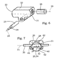
- FIG. 6 is a perspective illustration of a gear housing with integrally connected exterior surfaces
- FIG. 7 is a front view of an actuator with an electric motor and an adjustable spindle, said actuator having the output shaft located in the center of the gear housing.
- FIGS. 1 and 2 show two different complete actuators for a motor vehicle, more specifically for a motor vehicle seat.
- An electric motor 20 with an attached reduction gear 22 has an output shaft 24 that is non-rotatably linked to an endless screw 23 that engages a spindle nut 26 .
- Said spindle nut 26 is part of a gear 28 and engages a spindle 30 ; it forms a surrounding grip around spindle 30 .
- Gear 28 further has a gear housing 32 . It is preferably made from a plastic material and can be made from one piece as shown in FIG. 6 , although it usually is composed of two or more housing parts. It may also be manufactured from a metal.
- the gear housing 32 has two partially cylindrical exterior surfaces 31 , 33 that are centered on a common pivot axis or central axis 34 .
- the two partially cylindrical exterior surfaces 31 , 33 are located at opposing 180 degree positions. A reduction gear needs not be provided, it may be eliminated.
- a gear retainer 40 forms a surrounding grip around the gear housing 32 .
- the gear housing 32 is carried and retained therein so as to be pivotal about the pivot axis 34 .
- the pivot axis 34 runs parallel to the output shaft 24 , FIG. 2 also showing the axial line 25 of the output shaft 24 .
- the gear retainer 40 has two partially cylindrical interior surfaces 42 , 43 . They are centered on the pivot axis 34 .
- the two partially cylindrical exterior surfaces 31 , 33 are also centered on the pivot axis 34 .
- the two partially cylindrical interior surfaces 42 , 43 match the two partially cylindrical exterior surfaces 31 , 33 , the surfaces respectively forming pairs 31 , 42 and 33 , 43 and being directly adjacent.
- the gear retainer 40 has at least one passageway or recess 44 for the spindle; in the implementation shown in FIG. 1 , there are provided two substantially opposing recesses 44 , in the implementation shown in FIG. 2 , there is provided only one recess 44 . In the implementations shown in the FIGS. 3 through 5 , there are respectively provided 2 opposing recesses 44 .
- the recesses extend in the circumferential direction, meaning peripherally about the pivot axis 34 , in an angular range leaving free the desired pivot angle for the spindle 30 to pivot about with respect to the gear retainer 40 .
- the maximum pivot angle is for example 30°, it may also be smaller.
- the gear retainer 40 is made from a portion of an extruded aluminium profile.
- a corresponding profile is simply cut to length and the at least one recess 44 is formed therein.
- the extruded profile innately has fastening holes 46 formed therein during manufacturing, said holes extending over the entire axial length and running parallel to the pivot axis 34 .
- these fastening holes 46 are located outside the inner volume of the gear retainer 40 . They may however also be provided in part or in whole in the inner volume, the exemplary embodiment shown in FIG. 7 for example offering enough space in the lower part inside the circular inner volume of the gear retainer 40 .
- the fastening holes 46 serve to connect the gear retainer 40 to a portion of the motor vehicle seat, for example to a side part 54 . Both the gear 28 and the electric motor 20 are fastened via the gear retainer 40 . In this case, the electric motor 20 needs no further fastening of its own.
- the gear housing 32 is made from a sheet metal blank 48 , which is rectangular. It is given the shape shown in FIG. 3 and is rolled for example.
- the fastening holes 46 are thereby also formed in the border regions.
- the passageways 44 may be formed therein prior to the rolling process or thereafter.
- the gear retainers 40 discussed hereto before are made from one piece. This also applies to the gear housing 32 shown in FIG. 7 .
- the two implementations illustrated in the FIGS. 4 and 5 show two-part gear housings 32 .
- a closure part 50 is still added to the actual gear housing 32 .
- the actual gear housings 32 in the embodiment shown in the FIGS. 4 or 5 are portions of an appropriate extruded profile in which the passageways 44 are formed separately.
- the free profile ends of the actual gear retainer 40 shown in FIG. 4 have outwardly directed lugs.
- the approximately roof-shaped closure part 50 has inwardly directed border regions for engaging behind said profile ends. A pre-bias may thus be introduced into the gear retainer 40 .
- the closure part 50 may also be slightly wedge-shaped.
- the closure part 50 is a bracket which concurrently forms nuts for fastening screws 52 .
- the gear retainer 40 forms a closed ring. This also applies to the exemplary implementation shown in FIG. 7 .
- the gear retainer 40 is not a completely closed ring but extends over far more than 270°.
- the fastening holes 46 are located on the profile ends.
- the actual gear retainer 40 is configured similar to the gear retainer 40 shown in FIG. 3 , this time however, it forms a closed ring thanks to the closure part 50 .
- the pivot axis 34 intersects the axial line 29 of the spindle 30 .
- this is also the case in the exemplary implementation shown in FIG. 1 .
- the axial line 29 of spindle 30 does not intersect the pivot axis 34
- pivot axis 34 rather coincides with the axial line 25 of the output shaft 24 .
- the advantage thereof is that the electric motor 20 may be secured separately at an appropriate location and does not necessarily move together with the gear 28 as this is the case in the implementations shown in FIG. 1 and in FIG. 2 for example. As a result, no space has to be left free for the electric motor 20 to move.
- the electric feeders of the electric motor 20 need not be movable for adjustment.
- the two partially cylindrical interior surfaces 42 , 44 of the gear retainer 40 are formed on one single component part, namely on the gear retainer 40 of the exemplary implementations shown in the FIGS. 1 , 2 , 3 and 7 or on the actual gear retainer 40 of the exemplary implementations shown in the FIGS. 4 and 5 .
- Such an integral embodiment of the two partially cylindrical interior surfaces 42 , 43 is advantageous and increases the precision, but it is not absolutely necessary.
- the gear housing 32 is realized by a single component part, such a construction is known from U.S. Pat. No. 4,802,374, see FIG. 5 thereof.
- the two partially cylindrical exterior surfaces 31 , 33 are now additionally formed on the one-piece gear housing 32 .
- the gear housing 32 shown in FIG. 6 is directly suitable for use in the exemplary implementation shown in FIG. 1 or 2 for example.
- FIG. 3 shows a side part 54 of a motor vehicle seat.
- This side part 54 stands for any part of the motor vehicle seat that is intended to be adjusted with respect to another part or with respect to which another part is intended to be adjusted.
- the side part 54 there are provided two holes that can be seen from FIG. 3 , they are directly aligned with the fastening holes 46 through which the two fastening screws 52 extend.
- the electric motor 20 is located on the same side of the side part 54 as the gear retainer 40 shown.
- a window 56 for the output shaft 24 is provided in the side part 54 .
- the side part 54 has a retaining device 64 for the gear retainer.
- a receiving part 58 is disposed on the spindle 30 which in this exemplary implementation is stationary but rotated through the gear 28 . It has holes through which it can be fastened to a part that is to be adjusted.
- FIG. 1 there is provided a corresponding retaining member 60 .
- FIG. 7 shows limit stops 62 that bound the pivot range of the gear 28 within the gear retainer 40 in at least one pivot direction about the pivot axis 34 .
Landscapes
- Engineering & Computer Science (AREA)
- Aviation & Aerospace Engineering (AREA)
- Transportation (AREA)
- Mechanical Engineering (AREA)
- Seats For Vehicles (AREA)
- Gear Transmission (AREA)
- Chairs For Special Purposes, Such As Reclining Chairs (AREA)
- General Details Of Gearings (AREA)
Abstract
Description
Claims (22)
Applications Claiming Priority (3)
| Application Number | Priority Date | Filing Date | Title |
|---|---|---|---|
| DE102005020171.7 | 2005-04-28 | ||
| DE102005020171 | 2005-04-28 | ||
| DE102005020171 | 2005-04-28 |
Publications (2)
| Publication Number | Publication Date |
|---|---|
| US20060260424A1 US20060260424A1 (en) | 2006-11-23 |
| US7775131B2 true US7775131B2 (en) | 2010-08-17 |
Family
ID=37395894
Family Applications (1)
| Application Number | Title | Priority Date | Filing Date |
|---|---|---|---|
| US11/413,299 Active 2027-07-05 US7775131B2 (en) | 2005-04-28 | 2006-04-28 | Actuator for a motor vehicle seat |
Country Status (4)
| Country | Link |
|---|---|
| US (1) | US7775131B2 (en) |
| JP (1) | JP2006306391A (en) |
| CN (1) | CN100478214C (en) |
| FR (1) | FR2885086B1 (en) |
Cited By (6)
| Publication number | Priority date | Publication date | Assignee | Title |
|---|---|---|---|---|
| US20100261566A1 (en) * | 2007-12-12 | 2010-10-14 | Zf Friedrichshafen Ag | Electric drive for a mobile vehicle |
| US20120325033A1 (en) * | 2010-02-11 | 2012-12-27 | Stefan Bosecker | Spindle gear unit having reinforcement |
| US20130015313A1 (en) * | 2011-07-16 | 2013-01-17 | Andreas Schmid | Adjustable system |
| US20170008423A1 (en) * | 2014-01-31 | 2017-01-12 | Johnson Controls Metals and Mechanisms GmbH & Co. KG | Actuator for a motor vehicle, in particular for a motor vehicle seat |
| USD874352S1 (en) * | 2017-04-20 | 2020-02-04 | Mackenzie Atlantic Tool & Die/Machining Ltd. | Slouch correction actuator |
| EP3665038B1 (en) * | 2017-08-11 | 2023-08-16 | KEIPER Seating Mechanisms Co., Ltd. | Longitudinal adjuster for a vehicle seat |
Families Citing this family (12)
| Publication number | Priority date | Publication date | Assignee | Title |
|---|---|---|---|---|
| DE102006027523A1 (en) * | 2006-06-14 | 2008-01-10 | Rk Rose + Krieger Gmbh Verbindungs- Und Positioniersysteme | linear unit |
| DE102008017017A1 (en) * | 2007-06-19 | 2008-12-24 | C. Rob. Hammerstein Gmbh & Co. Kg | Actuator for a motor vehicle with a transmission housing |
| FR2921595B1 (en) * | 2007-09-27 | 2016-01-15 | Hammerstein Gmbh C Rob | ADJUSTING DEVICE FOR A MOTOR VEHICLE SEAT COMPRISING AN ELECTRIC MOTOR AND A GEAR RELATING THERETO |
| DE102008036644A1 (en) | 2007-09-27 | 2009-04-02 | C. Rob. Hammerstein Gmbh & Co. Kg | Adjustment device for a motor vehicle seat with an electric motor with a transmission connected thereto |
| DE102008028726A1 (en) | 2007-09-27 | 2009-04-02 | C. Rob. Hammerstein Gmbh & Co. Kg | Adjusting device for adjusting head rest of motor vehicle seat, has crash sensor emitting signal during excess voltage in driving condition, where excess voltage amounts to specific percentage of value of normal operating voltage |
| FR2926040A1 (en) | 2008-01-08 | 2009-07-10 | Hammerstein Gmbh C Rob | MOTORIZED DEVICE FOR THE LONGITUDINAL ADJUSTMENT OF A SEAT OF A MOTOR VEHICLE |
| CN102131674B (en) * | 2008-08-19 | 2014-05-14 | C.劳勃.汉默斯坦两合有限公司 | Base frame of vehicle seat comprising two pairs of rails, rockers and one seat support |
| DE102010000715A1 (en) * | 2010-01-07 | 2011-07-14 | Robert Bosch GmbH, 70469 | Fixing a stop washer |
| DE102010041570A1 (en) * | 2010-09-28 | 2012-03-29 | Brose Fahrzeugteile Gmbh & Co. Kommanditgesellschaft, Coburg | Adjusting device with a spindle gear |
| DE102016225835A1 (en) | 2016-09-21 | 2018-03-22 | Adient Luxembourg Holding S.a.r.l. | ADJUSTMENT DEVICE FOR A VEHICLE SEAT, AND METHOD FOR MOUNTING AN ADJUSTMENT DEVICE |
| US11713609B2 (en) | 2019-11-01 | 2023-08-01 | Magna Closures Inc. | Powered door unit with improved mounting arrangement |
| DE102021108767A1 (en) | 2021-04-08 | 2022-10-13 | Sitech Sitztechnik Gmbh | seat rail |
Citations (25)
| Publication number | Priority date | Publication date | Assignee | Title |
|---|---|---|---|---|
| US3617021A (en) | 1969-08-11 | 1971-11-02 | Dura Corp | Vehicle seat supporting and adjusting mechanism |
| US4108021A (en) * | 1975-12-18 | 1978-08-22 | Jeep Corporation | Transfer case |
| US4172367A (en) * | 1977-05-16 | 1979-10-30 | Mccusker James D | Torque tube and method for mounting and maintaining power transmitting forces |
| US4216624A (en) * | 1978-03-21 | 1980-08-12 | Rockwell-Golde, G.M.B.H. | Window winder for slidable windows, especially for automobiles |
| WO1986006036A1 (en) | 1985-04-18 | 1986-10-23 | Equipements Automobiles Marchal | Control device for displacing an element, particularly a seat or parts of a seat of a motor vehicle with respect to a frame |
| US4947699A (en) * | 1985-09-10 | 1990-08-14 | Viktor Zupancic | Worm reduction gear assembly |
| US5052752A (en) * | 1990-06-21 | 1991-10-01 | Fisher Dynamics Corporation | Infinitely adjustable linear seat recliner |
| US5163335A (en) * | 1991-07-15 | 1992-11-17 | Patrick D. Isom | Universal starter motor assembly |
| US5199764A (en) * | 1989-07-24 | 1993-04-06 | Fisher Dynamics Corporation | Power linear seat recliner |
| US5259257A (en) * | 1991-10-31 | 1993-11-09 | Ikeda Bussan Co., Ltd. | Power slider |
| US5957117A (en) * | 1997-08-07 | 1999-09-28 | Siemens Canada Limited | Automotive emission control valve assembly |
| US6073893A (en) | 1997-08-18 | 2000-06-13 | Aisin Seiki Kabushiki Kaisha | Power seat device |
| US6081647A (en) * | 1998-01-05 | 2000-06-27 | Molex Incorporated | Fiber optic connector receptacle |
| US6260922B1 (en) * | 1998-08-12 | 2001-07-17 | Ernst-Reiner Frohnhaus | Vehicle seat with an adjusting device provided with a spindle and an associated spindle nut |
| US6322146B1 (en) | 2000-02-14 | 2001-11-27 | Fisher Dynamics Corporation | Linear recliner with plastic housing |
| US20020073790A1 (en) * | 2000-12-19 | 2002-06-20 | Martin Wiesler | Transmission-drive unit, in particular for a seat adjustment or servo steering with at least one supporting element |
| US6575421B1 (en) * | 1999-11-25 | 2003-06-10 | C. Rob. Hammerstein Gmbh & Co. Kg | Adjusting device for a vehicle seat with a spindle and an associated spindle nut |
| WO2003068551A1 (en) | 2002-02-13 | 2003-08-21 | Brose Fahrzeugteile Gmbh & Co. Kg, Coburg | Spindle or worm drive for adjustment devices in motor vehicles |
| US20040188589A1 (en) * | 2003-03-27 | 2004-09-30 | Unisia Jkc Steering Systems Co., Ltd. | Structure for fixing steering-gear housing |
| US20050044974A1 (en) * | 2003-08-27 | 2005-03-03 | Lear Corporation | Drive Nut with Structural Extrusion Drive Area for Vehicle Seat Adjuster |
| US6915998B2 (en) * | 2002-07-06 | 2005-07-12 | Keiper Gmbh & Co. Kg | Longitudinal adjuster for a vehicle seat |
| US20060060015A1 (en) * | 2004-09-21 | 2006-03-23 | Wolfram Hofschulte | Gearing mechanism and vehicle seat with such a gearing mechanism |
| US7048244B2 (en) * | 2003-01-29 | 2006-05-23 | Dura Global Technologies, Inc. | Seat track assembly and method of manufacture |
| US7051986B1 (en) * | 1998-04-06 | 2006-05-30 | Brose Fahrzeugteile Gmbh & Co., Kg | Spindle and worm drive for adjusting devices in motor vehicles |
| US7340974B2 (en) * | 2003-02-24 | 2008-03-11 | C. Rob. Hammerstein Gmbh & Co. Kg | Spindle gear for an adjusting device in a motor vehicle seat |
Family Cites Families (1)
| Publication number | Priority date | Publication date | Assignee | Title |
|---|---|---|---|---|
| US6073983A (en) * | 1999-06-02 | 2000-06-13 | Schroeder; James A. | Magnetic remote-retrieval device |
-
2006
- 2006-04-27 CN CNB2006100799147A patent/CN100478214C/en not_active Expired - Fee Related
- 2006-04-27 FR FR0651496A patent/FR2885086B1/en active Active
- 2006-04-28 US US11/413,299 patent/US7775131B2/en active Active
- 2006-04-28 JP JP2006127042A patent/JP2006306391A/en active Pending
Patent Citations (28)
| Publication number | Priority date | Publication date | Assignee | Title |
|---|---|---|---|---|
| US3617021A (en) | 1969-08-11 | 1971-11-02 | Dura Corp | Vehicle seat supporting and adjusting mechanism |
| US4108021A (en) * | 1975-12-18 | 1978-08-22 | Jeep Corporation | Transfer case |
| US4172367A (en) * | 1977-05-16 | 1979-10-30 | Mccusker James D | Torque tube and method for mounting and maintaining power transmitting forces |
| US4216624A (en) * | 1978-03-21 | 1980-08-12 | Rockwell-Golde, G.M.B.H. | Window winder for slidable windows, especially for automobiles |
| WO1986006036A1 (en) | 1985-04-18 | 1986-10-23 | Equipements Automobiles Marchal | Control device for displacing an element, particularly a seat or parts of a seat of a motor vehicle with respect to a frame |
| US4802374A (en) * | 1985-04-18 | 1989-02-07 | Equipments Automobiles Marchal | Device for controlling the displacement of an element, in particular of a seat or parts of a seat of a motor vehicle, in relation to a base |
| US4947699A (en) * | 1985-09-10 | 1990-08-14 | Viktor Zupancic | Worm reduction gear assembly |
| US5199764A (en) * | 1989-07-24 | 1993-04-06 | Fisher Dynamics Corporation | Power linear seat recliner |
| US5052752A (en) * | 1990-06-21 | 1991-10-01 | Fisher Dynamics Corporation | Infinitely adjustable linear seat recliner |
| US5163335A (en) * | 1991-07-15 | 1992-11-17 | Patrick D. Isom | Universal starter motor assembly |
| US5259257A (en) * | 1991-10-31 | 1993-11-09 | Ikeda Bussan Co., Ltd. | Power slider |
| US5957117A (en) * | 1997-08-07 | 1999-09-28 | Siemens Canada Limited | Automotive emission control valve assembly |
| US6073893A (en) | 1997-08-18 | 2000-06-13 | Aisin Seiki Kabushiki Kaisha | Power seat device |
| US6081647A (en) * | 1998-01-05 | 2000-06-27 | Molex Incorporated | Fiber optic connector receptacle |
| US7051986B1 (en) * | 1998-04-06 | 2006-05-30 | Brose Fahrzeugteile Gmbh & Co., Kg | Spindle and worm drive for adjusting devices in motor vehicles |
| US7143513B2 (en) * | 1998-04-06 | 2006-12-05 | Brose Fahrzeugteile Gmbh & Co. Kg, Coburg | Method of forming a housing for gear elements |
| US6260922B1 (en) * | 1998-08-12 | 2001-07-17 | Ernst-Reiner Frohnhaus | Vehicle seat with an adjusting device provided with a spindle and an associated spindle nut |
| US6575421B1 (en) * | 1999-11-25 | 2003-06-10 | C. Rob. Hammerstein Gmbh & Co. Kg | Adjusting device for a vehicle seat with a spindle and an associated spindle nut |
| US6322146B1 (en) | 2000-02-14 | 2001-11-27 | Fisher Dynamics Corporation | Linear recliner with plastic housing |
| US20020073790A1 (en) * | 2000-12-19 | 2002-06-20 | Martin Wiesler | Transmission-drive unit, in particular for a seat adjustment or servo steering with at least one supporting element |
| WO2003068551A1 (en) | 2002-02-13 | 2003-08-21 | Brose Fahrzeugteile Gmbh & Co. Kg, Coburg | Spindle or worm drive for adjustment devices in motor vehicles |
| US20050126333A1 (en) * | 2002-02-13 | 2005-06-16 | Dittmar Dohles | Spindle or worm drive for adjustment devices in motor vehicles |
| US6915998B2 (en) * | 2002-07-06 | 2005-07-12 | Keiper Gmbh & Co. Kg | Longitudinal adjuster for a vehicle seat |
| US7048244B2 (en) * | 2003-01-29 | 2006-05-23 | Dura Global Technologies, Inc. | Seat track assembly and method of manufacture |
| US7340974B2 (en) * | 2003-02-24 | 2008-03-11 | C. Rob. Hammerstein Gmbh & Co. Kg | Spindle gear for an adjusting device in a motor vehicle seat |
| US20040188589A1 (en) * | 2003-03-27 | 2004-09-30 | Unisia Jkc Steering Systems Co., Ltd. | Structure for fixing steering-gear housing |
| US20050044974A1 (en) * | 2003-08-27 | 2005-03-03 | Lear Corporation | Drive Nut with Structural Extrusion Drive Area for Vehicle Seat Adjuster |
| US20060060015A1 (en) * | 2004-09-21 | 2006-03-23 | Wolfram Hofschulte | Gearing mechanism and vehicle seat with such a gearing mechanism |
Cited By (10)
| Publication number | Priority date | Publication date | Assignee | Title |
|---|---|---|---|---|
| US20100261566A1 (en) * | 2007-12-12 | 2010-10-14 | Zf Friedrichshafen Ag | Electric drive for a mobile vehicle |
| US8439786B2 (en) * | 2007-12-12 | 2013-05-14 | Zf Friedrichshafen Ag | Electric drive for a mobile vehicle |
| US20120325033A1 (en) * | 2010-02-11 | 2012-12-27 | Stefan Bosecker | Spindle gear unit having reinforcement |
| US9145068B2 (en) * | 2010-02-11 | 2015-09-29 | Brose Fahrzeugteile Gmbh & Co. Kg, Coburg | Spindle gear unit having reinforcement |
| US20130015313A1 (en) * | 2011-07-16 | 2013-01-17 | Andreas Schmid | Adjustable system |
| US20170008423A1 (en) * | 2014-01-31 | 2017-01-12 | Johnson Controls Metals and Mechanisms GmbH & Co. KG | Actuator for a motor vehicle, in particular for a motor vehicle seat |
| US10688883B2 (en) * | 2014-01-31 | 2020-06-23 | Johnson Controls Metals and Mechanisms GmbH & Co. KG | Actuator for a motor vehicle, in particular for a motor vehicle seat |
| USD874352S1 (en) * | 2017-04-20 | 2020-02-04 | Mackenzie Atlantic Tool & Die/Machining Ltd. | Slouch correction actuator |
| EP3665038B1 (en) * | 2017-08-11 | 2023-08-16 | KEIPER Seating Mechanisms Co., Ltd. | Longitudinal adjuster for a vehicle seat |
| US11745625B2 (en) * | 2017-08-11 | 2023-09-05 | Keiper Seating Mechanisms Co., Ltd. | Longitudinal adjuster for a vehicle seat |
Also Published As
| Publication number | Publication date |
|---|---|
| JP2006306391A (en) | 2006-11-09 |
| FR2885086A1 (en) | 2006-11-03 |
| CN100478214C (en) | 2009-04-15 |
| US20060260424A1 (en) | 2006-11-23 |
| FR2885086B1 (en) | 2012-01-13 |
| CN1865039A (en) | 2006-11-22 |
Similar Documents
| Publication | Publication Date | Title |
|---|---|---|
| US7775131B2 (en) | Actuator for a motor vehicle seat | |
| US10100906B2 (en) | Spindle drive for an adjustment element of a motor vehicle | |
| CN103095041A (en) | Geared decelerated motor | |
| US20170015345A1 (en) | Steering column for a motor vehicle | |
| DE10247311A1 (en) | Pressure sensor to be mounted in a pneumatic tire and its support | |
| DE102014113842B4 (en) | derailleur | |
| US6718593B2 (en) | Wiper device | |
| DE102009017054A1 (en) | Steering column for motor vehicles | |
| EP2723588B1 (en) | Rolling piston for a rolling lobe air spring | |
| US20080178701A1 (en) | Tilt-and-telescope steering apparatus | |
| US8944208B2 (en) | Power steering apparatus | |
| EP2233381A1 (en) | Cost-effective gear rack steering gear | |
| JPH07301230A (en) | Plastic bearing for stabilizer in automobile | |
| EP2399780A1 (en) | External rear view mirror | |
| EP3350034A1 (en) | Bearing device and electromechanical brake force booster | |
| EP0794106B2 (en) | Subframe for the steered wheels of a motor vehicle | |
| US10994649B2 (en) | Adjusting screw | |
| DE102011002888B4 (en) | Adapter for precise and positionally accurate mounting of a mirror unit, exterior mirror assembly, set of adapters and method of attachment | |
| KR20090092951A (en) | A gear box of seat sliding device for a car | |
| DE2916970C3 (en) | Automotive headlights | |
| US7458628B2 (en) | Vehicle sun visors with support rods | |
| WO2016141937A1 (en) | Linear actuating drive and method for assembling an actuating drive | |
| DE102015213356A1 (en) | Driven torsion beam axle of a vehicle with two trailing arms | |
| DE102012011601A1 (en) | Constraint free fastening system, particularly for attaching steering gear housing at vehicle body, has component with two fastening feet, while another component is provided with two receptacles | |
| EP1516782B1 (en) | Actuator for a headlamp |
Legal Events
| Date | Code | Title | Description |
|---|---|---|---|
| AS | Assignment |
Owner name: C. ROB HAMMERSTEIN GMBH & CO. KG, GERMANY Free format text: ASSIGNMENT OF ASSIGNORS INTEREST;ASSIGNORS:BECKER, BURKHARD;BENEKER, DR. WILFRIED;REEL/FRAME:017941/0282 Effective date: 20060404 |
|
| STCF | Information on status: patent grant |
Free format text: PATENTED CASE |
|
| FPAY | Fee payment |
Year of fee payment: 4 |
|
| MAFP | Maintenance fee payment |
Free format text: PAYMENT OF MAINTENANCE FEE, 8TH YEAR, LARGE ENTITY (ORIGINAL EVENT CODE: M1552) Year of fee payment: 8 |
|
| AS | Assignment |
Owner name: JOHNSON CONTROLS METALS AND MECHANISMS GMBH & CO. KG, GERMANY Free format text: CHANGE OF NAME;ASSIGNOR:C. ROB. HAMMERSTEIN GMBH & CO. KG;REEL/FRAME:055026/0770 Effective date: 20170421 |
|
| AS | Assignment |
Owner name: ADIENT LUXEMBOURG HOLDING S.A R.L., LUXEMBOURG Free format text: ASSIGNMENT OF ASSIGNORS INTEREST;ASSIGNOR:JOHNSON CONTROLS METALS AND MECHANISMS GMBH & CO. KG;REEL/FRAME:055170/0344 Effective date: 20200724 |
|
| AS | Assignment |
Owner name: KEIPER SEATING MECHANISMS CO., LTD., CHINA Free format text: CHANGE OF NAME;ASSIGNOR:ADIENT YANFENG SEATING MECHANISM CO., LTD;REEL/FRAME:057037/0905 Effective date: 20210118 Owner name: ADIENT YANFENG SEATING MECHANISM CO., LTD, CHINA Free format text: NUNC PRO TUNC ASSIGNMENT;ASSIGNOR:ADIENT LUXEMBOURG HOLDING S.A.R.L.;REEL/FRAME:057037/0931 Effective date: 20210728 |
|
| MAFP | Maintenance fee payment |
Free format text: PAYMENT OF MAINTENANCE FEE, 12TH YEAR, LARGE ENTITY (ORIGINAL EVENT CODE: M1553); ENTITY STATUS OF PATENT OWNER: LARGE ENTITY Year of fee payment: 12 |