US77742A - Self and bradfobd stetson - Google Patents
Self and bradfobd stetson Download PDFInfo
- Publication number
- US77742A US77742A US77742DA US77742A US 77742 A US77742 A US 77742A US 77742D A US77742D A US 77742DA US 77742 A US77742 A US 77742A
- Authority
- US
- United States
- Prior art keywords
- tool
- post
- socket
- self
- bradfobd
- Prior art date
- Legal status (The legal status is an assumption and is not a legal conclusion. Google has not performed a legal analysis and makes no representation as to the accuracy of the status listed.)
- Expired - Lifetime
Links
- 101100187684 Drosophila melanogaster Ntmt gene Proteins 0.000 description 1
- 150000001875 compounds Chemical class 0.000 description 1
- 238000010276 construction Methods 0.000 description 1
- 230000013011 mating Effects 0.000 description 1
Images
Classifications
-
- B—PERFORMING OPERATIONS; TRANSPORTING
- B23—MACHINE TOOLS; METAL-WORKING NOT OTHERWISE PROVIDED FOR
- B23B—TURNING; BORING
- B23B29/00—Holders for non-rotary cutting tools; Boring bars or boring heads; Accessories for tool holders
- B23B29/04—Tool holders for a single cutting tool
-
- Y—GENERAL TAGGING OF NEW TECHNOLOGICAL DEVELOPMENTS; GENERAL TAGGING OF CROSS-SECTIONAL TECHNOLOGIES SPANNING OVER SEVERAL SECTIONS OF THE IPC; TECHNICAL SUBJECTS COVERED BY FORMER USPC CROSS-REFERENCE ART COLLECTIONS [XRACs] AND DIGESTS
- Y10—TECHNICAL SUBJECTS COVERED BY FORMER USPC
- Y10T—TECHNICAL SUBJECTS COVERED BY FORMER US CLASSIFICATION
- Y10T82/00—Turning
- Y10T82/25—Lathe
- Y10T82/2585—Tool rest
- Y10T82/2591—Tool post
Definitions
- Figure 2 is a perspective view of the same on a reduced scale.
- the object of invention is toA construct a. tool-post for lathes, planing-machines, die., in -Such a. manner as to enable the point of the cutting-tool tohe readily adj usted in any desired position relatively to the material to be operatednpou'; and the invention consists in attaching the tool-postte the base-plate by means of n. balland-socket joint, in combination with a collnr, fitting upon the outer surface nf the socket portion, thus forming a double bearing.
- wbichpasses through a. slot in the upper portion ofthe post and is held in position by means of a .screw passing through the top of theA post in the usual manner.
- A represents the baise-plate, provided with o hole, a, for tho reception of a holt
- one end of the bcse-plaitc is a hemispherical casing or socket, A', provided with au opening at the top.
- A' hemispherical casing or socket
- i Within this socket is tted Ithe lower portion ot ⁇ the tool-post, forming a. half ball-socket joint.
- the collar C On the outer upper portion of' the socket A is supported the collar C, ⁇ its'contact surface being curved to correspond with the curvedA surface of the said socket.
- Thepp'ortion A serves thc' double purpose of a. ball' and socklet, constituting n socket to the portion B' ot" the tool-post, und as a. ball to the collar-'0, the latter being then the socket, thus forming a double or compound ball-und-'sockct joint.
- D is the cutting-tool, which passes through n slot inthe tool-post, and rests upon the upper surface of the collar C. Fis the screw, which passes down through the upper portion ot the tool-post,-a;ndbearing upon the cutting-tool, secures all the parts in position.
- the tool-post B may be turned and inclined in any direction, so 'as tu adapt the -point of fthe cutting-tool to any position that may bo required, by simply loosening the 'screw F; and upon ⁇ tightening the screw, it will be firmly held in position. g.
- the device is applicable to ironzmd wood-turninglathes, iron-planers, und 'shapingmachines Having thus described my invention, what I claim as new, and desire to secure by Letters Patent, is
Landscapes
- Engineering & Computer Science (AREA)
- Mechanical Engineering (AREA)
- Treatment Of Fiber Materials (AREA)
Description
i @uitrit -tstrs afrltt'ffire.
SELF AND BRADFORD S'IETSONQOF' SAM-E PLAGE.
Letters Patent No. 77,742, `dated May 1 2, 1868.
IMPROVEMENT IN TOOL-POST FOR LAfIHB 0R PLANINGfMIAGHINES.
@he ,Stlgrhnlc nfrrrrt tu in their @titers ntmt mit mating mrt at ille time.
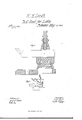
Be it known that I, WILL-IAM H. LEACH, of Uxbridge, in the county of Worcester, and State of Massachusetts, have invented n new andirnproved Tool-Post for Lathes, Flaming-Machines, &c., of which the followinglis affull, clear, und exact description, reference being had to the accompanying drawings, making a.4 part of this speciication, in whicb Figure 1 represents n. vertical'seetion of n tool-post embodying my invention.
Figure 2 is a perspective view of the same on a reduced scale. y
The object of invention is toA construct a. tool-post for lathes, planing-machines, die., in -Such a. manner as to enable the point of the cutting-tool tohe readily adj usted in any desired position relatively to the material to be operatednpou'; and the invention consists in attaching the tool-postte the base-plate by means of n. balland-socket joint, in combination with a collnr, fitting upon the outer surface nf the socket portion, thus forming a double bearing. Upon the colla-r 4is supportedthe cutting-tool, wbichpasses through a. slot in the upper portion ofthe post, and is held in position by means of a .screw passing through the top of theA post in the usual manner.
Referring to the drawings, A represents the baise-plate, provided with o hole, a, for tho reception of a holt,
by which it is secured to the frame of the machine. -At one end of the bcse-plaitc is a hemispherical casing or socket, A', provided with au opening at the top. i Within this socket is tted Ithe lower portion ot`the tool-post, forming a. half ball-socket joint. On the outer upper portion of' the socket A is supported the collar C,` its'contact surface being curved to correspond with the curvedA surface of the said socket. Thepp'ortion A. serves thc' double purpose of a. ball' and socklet, constituting n socket to the portion B' ot" the tool-post, und as a. ball to the collar-'0, the latter being then the socket, thus forming a double or compound ball-und-'sockct joint.
D is the cutting-tool, which passes through n slot inthe tool-post, and rests upon the upper surface of the collar C. Fis the screw, which passes down through the upper portion ot the tool-post,-a;ndbearing upon the cutting-tool, secures all the parts in position.
It will thus be seen that the tool-post B may be turned and inclined in any direction, so 'as tu adapt the -point of fthe cutting-tool to any position that may bo required, by simply loosening the 'screw F; and upon `tightening the screw, it will be firmly held in position. g.
It will be obscrvedthatthe tool-post is-held by'a, double frictional bearing, thcnction ofthe screw serving to dr'aw the portion B against the'inner side of the sock-et A, and at the same time pressing the/collar C upon the outer'surface of the socket, which holds the post firmly in any desired position against nnyforce that may bee'xerted upon. the cutting-tool. Y
The device is applicable to ironzmd wood-turninglathes, iron-planers, und 'shapingmachines Having thus described my invention, what I claim as new, and desire to secure by Letters Patent, is
The construction of a. tool-post, i'or a lathe or other machine, 'with thejoint AB, in combination with the collar C and set-screw F, substantially as and for the purpose set forth.
" In testimony whereof, I have signed my name to this specification in the presence of two Asubscribing witnesses.
' i WM. H. LEACH.
Witnesses:
GEO. `W. HoBBs, BRADFORD -S'rnTsoN.
Publications (1)
| Publication Number | Publication Date |
|---|---|
| US77742A true US77742A (en) | 1868-05-12 |
Family
ID=2147244
Family Applications (1)
| Application Number | Title | Priority Date | Filing Date |
|---|---|---|---|
| US77742D Expired - Lifetime US77742A (en) | Self and bradfobd stetson |
Country Status (1)
| Country | Link |
|---|---|
| US (1) | US77742A (en) |
-
0
- US US77742D patent/US77742A/en not_active Expired - Lifetime
Similar Documents
| Publication | Publication Date | Title |
|---|---|---|
| US7016A (en) | Mill for grinding | |
| US77742A (en) | Self and bradfobd stetson | |
| US536845A (en) | Island | |
| US90783A (en) | Improved auxiliary jaw for planer-chuck | |
| US89335A (en) | Improved tool-adjuster for lathes | |
| US92541A (en) | Improvement in auger-handles | |
| US89688A (en) | Improved tool-holder | |
| US68698A (en) | Peters | |
| US461039A (en) | Truss | |
| US1246226A (en) | Tool-post. | |
| US88833A (en) | Improvement in carpenters gauge | |
| US84697A (en) | Improved device for cutting out sections of annular cylinders | |
| US80770A (en) | kussell | |
| US96453A (en) | Improvement in leather-punches | |
| US70830A (en) | William gleason | |
| US93808A (en) | William a | |
| US103926A (en) | Improvement in calipeks | |
| US127026A (en) | Improvement in bench-planes | |
| US140081A (en) | Improvement in pencil attachments for dividers | |
| US85334A (en) | Improved expanding- drill | |
| US65562A (en) | Improvement in joinees planes | |
| US114229A (en) | Improvement in portable drilling-machines | |
| US101493A (en) | Marcellus a | |
| US77211A (en) | Improvement in cutting-tools for planing and milling machines | |
| US95297A (en) | Improved chuck |