US7772843B2 - Method for processing a distortion-corrected 2D or 3D reconstruction image recorded by a magnetic resonance device - Google Patents
Method for processing a distortion-corrected 2D or 3D reconstruction image recorded by a magnetic resonance device Download PDFInfo
- Publication number
- US7772843B2 US7772843B2 US11/989,243 US98924306A US7772843B2 US 7772843 B2 US7772843 B2 US 7772843B2 US 98924306 A US98924306 A US 98924306A US 7772843 B2 US7772843 B2 US 7772843B2
- Authority
- US
- United States
- Prior art keywords
- distortion
- gradient field
- reconstruction image
- algorithm
- input value
- Prior art date
- Legal status (The legal status is an assumption and is not a legal conclusion. Google has not performed a legal analysis and makes no representation as to the accuracy of the status listed.)
- Expired - Fee Related, expires
Links
Images

Classifications
-
- G—PHYSICS
- G01—MEASURING; TESTING
- G01R—MEASURING ELECTRIC VARIABLES; MEASURING MAGNETIC VARIABLES
- G01R33/00—Arrangements or instruments for measuring magnetic variables
- G01R33/20—Arrangements or instruments for measuring magnetic variables involving magnetic resonance
- G01R33/44—Arrangements or instruments for measuring magnetic variables involving magnetic resonance using nuclear magnetic resonance [NMR]
- G01R33/48—NMR imaging systems
- G01R33/54—Signal processing systems, e.g. using pulse sequences ; Generation or control of pulse sequences; Operator console
- G01R33/56—Image enhancement or correction, e.g. subtraction or averaging techniques, e.g. improvement of signal-to-noise ratio and resolution
- G01R33/565—Correction of image distortions, e.g. due to magnetic field inhomogeneities
- G01R33/56518—Correction of image distortions, e.g. due to magnetic field inhomogeneities due to eddy currents, e.g. caused by switching of the gradient magnetic field
Definitions
- At least one embodiment of the invention relates to a method for processing a 2D or 3D reconstruction image that is recorded by a magnetic resonance device.
- a method for processing a 2D or 3D reconstruction image that is recorded by a magnetic resonance device.
- it may relate to one comprising a gradient coil that generates a gradient field, and is distortion-corrected with regard to a given nonlinearity—leading to an image distortion—of the gradient field by using an algorithm that processes the measurement signals at various measuring points lying in the imaging volume, which algorithm processes, with respect to each signal processed by it, a first input value describing the real gradient field given at the real measuring point of the signal.
- a magnetic resonance device serves for recording or generating images of an examination object that are acquired by the signals resulting from a radio frequency excitation and in which the image is subsequently determined or reconstructed.
- a basic field magnet is used to generate a basic field that is as homogeneous as possible and has a homogeneity volume of defined homogeneity.
- superposed on the field for imaging purposes is a gradient field generated by way of a gradient coil and having field components in the x-, y- and z-directions.
- a radio frequency coil produces an RF pulse for the spin excitation that leads to the signal generation.
- the recording of a magnetic resonance image or a tomogram is preferably performed at the center of the approximately spherical homogeneity volume, the so-called isocenter.
- the slice set to be measured is positioned at the isocenter by automatic table displacement for each protocol used for a measurement, that is to say a signal recording for imaging. That is to say; for each slice to be recorded the patient is readjusted as necessary such that the body region in which the slice lies is positioned at the isocenter. This ensures the best possible basic field homogeneity and gradient linearity, and thus image quality, for the volume to be imaged.
- the slice planning may be done in the context of the isocentering concept exclusively on distortion-corrected images. Such images are corrected by geometric distortions that result from gradient nonlinearities.
- At least one embodiment of the invention involves a problem of specifying a method that is improved by comparison.
- a 2D or 3D reconstruction image processing method in which method the distortion-corrected reconstruction image is back transformed into a distortion-uncorrected reconstruction image by using the first algorithm or a second algorithm corresponding thereto and to which there is given as second input value in relation to each signal processed by it one such as describes a fictitious gradient field at the respective distorted measuring point at which the processed signal appears, and is raised or lowered by the nonlinear field component of the real gradient field compared with the linear ideal gradient field.
- At least one embodiment of the invention involves an idea of an inverse distortion correction in the context of which use is made of the algorithm, or of an algorithm normally used for distortion correction but which is given only another input value that describes the gradient field.
- This input value describes a “fictitious” or “effective” gradient field that describes the back transformation, and thus consequently images the nonlinear field component, as considered in the context of the distortion correction, with back transformation or inversely.
- a transformation, induced by distortion correction, of the actually recorded measurement signal from the distortion-induced measuring point to the real measuring point is thereby cancelled or inverted, that is to say the signals of the distortion-corrected image, which appear at the real measuring points as a consequence of the correction, are imaged back to the distortion-induced “wrong” measuring point.
- the inventive method of at least one embodiment thus permits exclusively the distortion-corrected 2D or 3D image data records or reconstruction images to be filed in the image data memory. These are generally used during operation. However, should it be necessary for the purpose of slice planning etc. to have to make recourse to an original image, it is possible when applying the inventive method to invert the distortion correction in a simple way and to use the distortion-corrected reconstruction image to determine the originally recorded distortion-uncorrected reconstruction image. In at least one embodiment, it is preferred to this end to use the same algorithm that was used for the distortion correction, all that is required is to determine and provide another input value in order to undertake the inverse correction, and so the inventive back transformation can also be performed very easily.
- the central “element” of the inverse correction method is the respective input value specific to pixel or measuring point.
- the distortion correction and of the back transformation for performance reasons it is not usual to process all pixels or signals at all measuring points. However, only a set of signals or measuring points between which interpolation is then carried out. If very high image qualities are desired, however, it is also possible to process every pixel or every signal.
- the first method step there is determined in relation to each measuring point in the distortion-corrected 2D or 3D reconstruction image by comparison with the ideal linear gradient field that nonlinear field component which is given at this point between the real gradient field, which is generated at this point, and the ideal gradient field. Subsequently, the value of the real, nonlinear gradient field at the real, distortion-corrected measuring point is used to determine the corresponding magnetic field value on the linear gradient field curve and the associated distorted measuring point, that is to say the distortion is determined in each of the three spatial directions for each measuring point in the distortion-corrected image.
- the second input value is determined, which results from the value of the field component of the linear ideal gradient field at the distorted measuring point (which corresponds to the value of the real field component at the actual measuring point) and from the nonlinear field component.
- This “effective gradient field value” at the respective distorted measuring point is subsequently used as a basis for the back transformation, and applied to the signal at the respective associated real, distortion-corrected measuring point. This mode of procedure is undertaken with reference to all two or three spatial directions. The determination of this “effective” or “fictitious” gradient field value or gradient field from the known real, nonlinear gradient field and the ideal, linear gradient field is extremely simple and can be performed very quickly.
- first or as second algorithm of one such as is given development coefficients of a multipole development of the gradient field, the development coefficients being determined with the aid of the second input values.
- a known way of correcting distortion is the so-called multipole development of the gradient field, which is a spherical function development in which the field is represented as the sum of various terms.
- development coefficients a and b that describe the respective nonlinearity at the respective point being considered.
- These development coefficients can be determined by using such a distortion correction algorithm with the aid of the fictitious or effective gradient field as previously described.
- the person skilled in the art is sufficiently well aware of the multipole development or the distortion correction with the use of development coefficients of a multipole development, and so there is no need to go into this in more detail.
- At least one embodiment of the invention further relates to a magnetic resonance device comprising an image processing device for processing measured signals and for image reconstruction, designed for carrying out the above-described method.
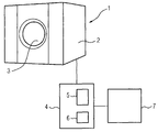
- FIG. 1 shows a schematic illustration of a magnetic resonance device
- FIG. 2 shows a diagram illustrating the determination of the fictitious or effective gradient field.
- FIG. 1 shows an inventive magnetic resonance device 1 including the signal recording section 2 , which includes the basic field magnet (not shown in more detail), a gradient coil 3 and a radio frequency coil (not shown in more detail) as well as the conventional further components, for which there is no need to give more detail.
- the magnet generates in the known manner a basic field with a homogeneity volume that is homogenized by using suitable shim devices such as, for example, iron shim plates or shim coils. These shim devices are likewise not illustrated in more detail, since they are sufficiently well known to the person skilled in the art.
- the gradient coil 3 is used to generate in a known way a gradient field that has three field components pointing in the respective spatial directions x, y, z and really exhibits a certain nonlinearity.
- control device 4 that controls the general operation of the system and thus also the image recording, and exhibits an image processing device 5 and an assigned image data memory 6 as well as an assigned monitor 7 for displaying the 3D reconstruction images generated via the image processing device 5 .
- the imaging signals which are received via the suitable signal recording devices or antennas in the recording section 2 and are processed in the image processing device 5 are given to the control device 4 .
- the image processing device 5 is designed for the 3D reconstruction and for correcting the image distortion resulting from the nonlinearities of the gradient field. At least one or, if appropriate, a number of reconstruction or correction algorithms are stored to this end. A person skilled in the art is sufficiently well aware of different reconstruction or correction algorithms.
- the image data memory 6 stores the distortion-corrected image data records or reconstruction images, but not the image data records or signal sets really recorded. If, instead of a distortion-corrected image, it is now necessary to output on the monitor 7 an originally recorded uncorrected image, the image processing device 5 is used to access the respective image data record in the image data memory 6 and undertake a back transformation of the image data, that is to say image data are determined as they were originally recorded. The 2D or 3D reconstruction image is then determined therewith.
- Magnetic resonance imaging is based on the time-dependent measurement of the magnetic resonance signals in conjunction with the application of a magnetic field gradient.
- these gradients exhibit exclusively linear terms.
- the corresponding relationships are explained below by way of example for the x-axis, in order to simplify the illustration. Of course, corresponding statements are also valid with reference to the y- and z-axes.
- the inventive method of at least one embodiment now offers a simple possibility for the back transformation of the distortion-corrected images into the associated distortion-uncorrected image by using existing methods or algorithms of the “normal” distortion correction.
- the sole difference is the use of a so-called “effective” or “fictitious” gradient field that describes the back transformation.
- the first step in calculating the “effective” gradient field at a point that is to be back transformed in the context of the inverse distortion correction is to determine at the real, distortion-corrected measuring point x t the nonlinear field component ⁇ B r (x t ) that results from the difference between the ideal gradient field ⁇ B i (x t ) at the point x t and the real gradient field B r (x t ). Subsequently, the field value that corresponds to the real gradient field value B r (x t ) at the point x t is determined on the ideal gradient field curve B i (x). As can be seen from FIG. 2 , the distorted measuring point x m results therefrom.
- the effective nonlinearity ⁇ B e (x m ) thus corresponds to the effective real nonlinearity ⁇ B r (x t ).
- These magnetic field values at the points x m i serve as input values for the distortion correction method being used, that is to say the correction algorithm being used, by which, for example, the distortion correction has already been performed in the context of the first processing.
- said development coefficients can, as already described, be determined from the magnetic field values B e (x m i ) at the points x m i .
Abstract
Description
B i(x)=G·x,
G being a constant value specifying the gradient strength.
B r(x)=B i(x)+ΔB r(x)=G·x+ΔB r(x),
ΔBr(x) describing the nonlinear field component, (here in the x-direction). The consequence of this additional nonlinear field component is that a measured signal from the point xt, that is to say the real measuring point, appears falsely at the point xm after the reconstruction. The following then applies for the true point xt:
B e(x)=G·x−ΔB e(x),
ΔBe(x) being a nonlinear component of the “effective” gradient field. Consequently, in complete analogy with the above equation, this “effective” gradient field must calculate xm in accordance with
the nonlinear component of the effective gradient field being determined in accordance with
ΔB e(x m)=ΔB r(x t).
Claims (6)
Applications Claiming Priority (4)
| Application Number | Priority Date | Filing Date | Title |
|---|---|---|---|
| DE102005034648.0 | 2005-07-25 | ||
| DE102005034648A DE102005034648B3 (en) | 2005-07-25 | 2005-07-25 | Method and device for processing a distortion-corrected 2D or 3D reconstruction image recorded with a magnetic resonance device |
| DE102005034648 | 2005-07-25 | ||
| PCT/EP2006/064212 WO2007012572A1 (en) | 2005-07-25 | 2006-07-13 | Method for processing a distortion-corrected 2d or 3d reconstruction image recorded by a magnetic resonance device |
Publications (2)
| Publication Number | Publication Date |
|---|---|
| US20090146657A1 US20090146657A1 (en) | 2009-06-11 |
| US7772843B2 true US7772843B2 (en) | 2010-08-10 |
Family
ID=36968669
Family Applications (2)
| Application Number | Title | Priority Date | Filing Date |
|---|---|---|---|
| US11/989,243 Expired - Fee Related US7772843B2 (en) | 2005-07-25 | 2006-07-13 | Method for processing a distortion-corrected 2D or 3D reconstruction image recorded by a magnetic resonance device |
| US12/801,801 Expired - Fee Related US8054079B2 (en) | 2005-07-25 | 2010-06-25 | Method for processing a distortion-corrected 2D or 3D reconstruction image recorded by a magnetic resonance device |
Family Applications After (1)
| Application Number | Title | Priority Date | Filing Date |
|---|---|---|---|
| US12/801,801 Expired - Fee Related US8054079B2 (en) | 2005-07-25 | 2010-06-25 | Method for processing a distortion-corrected 2D or 3D reconstruction image recorded by a magnetic resonance device |
Country Status (6)
| Country | Link |
|---|---|
| US (2) | US7772843B2 (en) |
| JP (1) | JP2009502281A (en) |
| CN (1) | CN101228456B (en) |
| DE (1) | DE102005034648B3 (en) |
| SE (1) | SE532371C2 (en) |
| WO (1) | WO2007012572A1 (en) |
Cited By (2)
| Publication number | Priority date | Publication date | Assignee | Title |
|---|---|---|---|---|
| US20100266186A1 (en) * | 2005-07-25 | 2010-10-21 | Franz Hebrank | Method for processing a distortion-corrected 2D or 3D reconstruction image recorded by a magnetic resonance device |
| US20140266198A1 (en) * | 2013-03-15 | 2014-09-18 | Tony Tadic | Method and apparatus for the measurement, characterization and correction of geometric distortions in magnetic resonance imaging |
Families Citing this family (13)
| Publication number | Priority date | Publication date | Assignee | Title |
|---|---|---|---|---|
| US9053562B1 (en) | 2010-06-24 | 2015-06-09 | Gregory S. Rabin | Two dimensional to three dimensional moving image converter |
| US9055873B2 (en) | 2010-12-29 | 2015-06-16 | General Electric Company | Method and system for maintaining iso center constant in an iso centric X-ray imaging system |
| DE102011006436A1 (en) * | 2011-03-30 | 2012-10-04 | Siemens Aktiengesellschaft | Method for correcting a distortion in a magnetic resonance image |
| JP6076603B2 (en) * | 2012-02-06 | 2017-02-08 | 東芝メディカルシステムズ株式会社 | Magnetic resonance imaging device |
| JP5904838B2 (en) * | 2012-03-28 | 2016-04-20 | 株式会社日立メディコ | Magnetic resonance imaging apparatus and image reconstruction method |
| CN103845054B (en) * | 2012-11-30 | 2017-12-22 | 上海联影医疗科技有限公司 | The method and device of magnetic resonance imaging lamella deformation warning |
| US9992021B1 (en) | 2013-03-14 | 2018-06-05 | GoTenna, Inc. | System and method for private and point-to-point communication between computing devices |
| US11039814B2 (en) | 2016-12-04 | 2021-06-22 | Exo Imaging, Inc. | Imaging devices having piezoelectric transducers |
| US10545211B2 (en) * | 2017-06-28 | 2020-01-28 | Synaptive Medical (Barbados) Inc. | Method of correcting gradient nonuniformity in gradient motion sensitive imaging applications |
| US11041921B2 (en) * | 2018-11-29 | 2021-06-22 | Canon Medical Systems Corporation | MRI apparatus, image processing apparatus, and MRI method |
| EP3902478A4 (en) * | 2018-12-27 | 2022-10-05 | Exo Imaging Inc. | Methods to maintain image quality in ultrasound imaging at reduced cost, size, and power |
| CN115644917A (en) | 2020-03-05 | 2023-01-31 | 艾科索成像公司 | Ultrasound imaging apparatus with programmable anatomical and flow imaging |
| GB2622823A (en) * | 2022-09-28 | 2024-04-03 | Elekta ltd | Motion monitoring for radiotherapy |
Citations (7)
| Publication number | Priority date | Publication date | Assignee | Title |
|---|---|---|---|---|
| US5099208A (en) | 1989-10-05 | 1992-03-24 | Vanderbilt University | Method for magnetic resonance imaging and related apparatus |
| DE19540837A1 (en) | 1995-10-30 | 1997-05-07 | Siemens Ag | Gradient non-linearity correction system for nuclear magnetic resonance tomography appts |
| DE19753093A1 (en) | 1997-11-29 | 1999-06-02 | Philips Patentverwaltung | MR procedure |
| DE10028560A1 (en) | 2000-06-09 | 2001-12-20 | Siemens Ag | Method for three dimensional correction of distortion of magnetic resonance images and suitable equipment based on correction coefficients derived during development and manufacture of magnetic resonance scanner |
| US6636756B2 (en) | 1999-11-30 | 2003-10-21 | General Electric Company | K-space synthesis for MR imaging in the presence of gradient field nonlinearity |
| DE10252852A1 (en) | 2002-11-13 | 2004-06-03 | Siemens Ag | Magnetic resonance imaging planning system for removing effects due to non-linearity of gradient field, has user interface allowing operator to move position of measured layer to region unaffected by field non-linearity |
| US20050024051A1 (en) | 2002-12-24 | 2005-02-03 | The University Of Queensland | Correction of magnetic resonance images |
Family Cites Families (4)
| Publication number | Priority date | Publication date | Assignee | Title |
|---|---|---|---|---|
| US6707300B2 (en) * | 2002-05-17 | 2004-03-16 | Ge Medical Systems Global Technology Co., Llc | Gradient non-linearity compensation in moving table MRI |
| US7202662B2 (en) * | 2002-12-11 | 2007-04-10 | The Board Of Trustees Of The Leland Stanford Junior University | Correction of the effect of gradient field non-linearities in phase contrast MRI |
| DE10337241B4 (en) * | 2003-08-13 | 2008-05-29 | Siemens Ag | Distortion-corrected magnetic resonance measurement and magnetic resonance apparatus |
| DE102005034648B3 (en) * | 2005-07-25 | 2007-03-29 | Siemens Ag | Method and device for processing a distortion-corrected 2D or 3D reconstruction image recorded with a magnetic resonance device |
-
2005
- 2005-07-25 DE DE102005034648A patent/DE102005034648B3/en not_active Expired - Fee Related
-
2006
- 2006-07-13 SE SE0800099A patent/SE532371C2/en unknown
- 2006-07-13 CN CN2006800272372A patent/CN101228456B/en not_active Expired - Fee Related
- 2006-07-13 WO PCT/EP2006/064212 patent/WO2007012572A1/en active Application Filing
- 2006-07-13 JP JP2008523304A patent/JP2009502281A/en not_active Abandoned
- 2006-07-13 US US11/989,243 patent/US7772843B2/en not_active Expired - Fee Related
-
2010
- 2010-06-25 US US12/801,801 patent/US8054079B2/en not_active Expired - Fee Related
Patent Citations (11)
| Publication number | Priority date | Publication date | Assignee | Title |
|---|---|---|---|---|
| US5099208A (en) | 1989-10-05 | 1992-03-24 | Vanderbilt University | Method for magnetic resonance imaging and related apparatus |
| DE19540837A1 (en) | 1995-10-30 | 1997-05-07 | Siemens Ag | Gradient non-linearity correction system for nuclear magnetic resonance tomography appts |
| US5886524A (en) | 1995-10-30 | 1999-03-23 | Siemens Aktiengesellschaft | Method of distortion correction for gradient non-linearities in nuclear magnetic resonance tomography apparatus |
| DE19753093A1 (en) | 1997-11-29 | 1999-06-02 | Philips Patentverwaltung | MR procedure |
| US6377043B1 (en) | 1997-11-29 | 2002-04-23 | Us Philips Corporation | Magnetic resonance method |
| US6636756B2 (en) | 1999-11-30 | 2003-10-21 | General Electric Company | K-space synthesis for MR imaging in the presence of gradient field nonlinearity |
| DE10028560A1 (en) | 2000-06-09 | 2001-12-20 | Siemens Ag | Method for three dimensional correction of distortion of magnetic resonance images and suitable equipment based on correction coefficients derived during development and manufacture of magnetic resonance scanner |
| US6501273B2 (en) | 2000-06-09 | 2002-12-31 | Siemens Aktiengesellschaft | Method for three-dimensionally correcting distortions and magnetic resonance apparatus for implementing the method |
| DE10252852A1 (en) | 2002-11-13 | 2004-06-03 | Siemens Ag | Magnetic resonance imaging planning system for removing effects due to non-linearity of gradient field, has user interface allowing operator to move position of measured layer to region unaffected by field non-linearity |
| US6882151B2 (en) | 2002-11-13 | 2005-04-19 | Siemens Aktiengesellschaft | MRT user interface allowing accurate slice planning based on a distortion-conrrected MRT overview image |
| US20050024051A1 (en) | 2002-12-24 | 2005-02-03 | The University Of Queensland | Correction of magnetic resonance images |
Non-Patent Citations (5)
| Title |
|---|
| Doran S.J.; A complete distortion correction for MR images; Phys. Med. Biol. 50 (2005), S. 1343-1361 (Epub Mar. 16, 2005); Others; 2005. |
| Janke, Andrew et al., "Use of Spherical Harmonic Deconvolution Methods to Compensate for Nonlinear Gradient Effects on MRI Images", Magnetic Resource in Medicine 52, 2004, pp. 115-122. |
| Kawanaka et al; Estimation of Static Magnetic Field and Gradient Fields From NMR Image Journal fof Physics Scientific Instruments, Bd. 19, Nr. 10, Oct. 1, 1986, Seiten 871-875, XP020017700 ISSN: 0022-3735; Magazine. |
| Langlois S. et al.; MIR Geometric Distortion: A Simple Approach to Correcting the Effects of Non-Linear Gradient Fields JMRI 9: 821-831, 1999; Magazine. |
| Morgan et al.; "Correction of spatial distortion in EPI due to inhomogeneous static magnetic field using the reversed gradient method"; J. Magn. Reson. Imaging 19 82994), S. 499-507; Others; 2004. |
Cited By (5)
| Publication number | Priority date | Publication date | Assignee | Title |
|---|---|---|---|---|
| US20100266186A1 (en) * | 2005-07-25 | 2010-10-21 | Franz Hebrank | Method for processing a distortion-corrected 2D or 3D reconstruction image recorded by a magnetic resonance device |
| US8054079B2 (en) * | 2005-07-25 | 2011-11-08 | Siemens Aktiengesellschaft | Method for processing a distortion-corrected 2D or 3D reconstruction image recorded by a magnetic resonance device |
| US20140266198A1 (en) * | 2013-03-15 | 2014-09-18 | Tony Tadic | Method and apparatus for the measurement, characterization and correction of geometric distortions in magnetic resonance imaging |
| US9857443B2 (en) * | 2013-03-15 | 2018-01-02 | University Health Network | Method and apparatus for the measurement, characterization and correction of geometric distortions in magnetic resonance imaging |
| US10082550B2 (en) * | 2013-03-15 | 2018-09-25 | University Health Network | Method and apparatus for the measurement, characterization and correction of geometric distortions in magnetic resonance imaging |
Also Published As
| Publication number | Publication date |
|---|---|
| CN101228456B (en) | 2013-04-17 |
| US20100266186A1 (en) | 2010-10-21 |
| SE0800099L (en) | 2008-01-16 |
| US8054079B2 (en) | 2011-11-08 |
| JP2009502281A (en) | 2009-01-29 |
| SE532371C2 (en) | 2009-12-29 |
| DE102005034648B3 (en) | 2007-03-29 |
| CN101228456A (en) | 2008-07-23 |
| WO2007012572A1 (en) | 2007-02-01 |
| US20090146657A1 (en) | 2009-06-11 |
Similar Documents
| Publication | Publication Date | Title |
|---|---|---|
| US7772843B2 (en) | Method for processing a distortion-corrected 2D or 3D reconstruction image recorded by a magnetic resonance device | |
| Morgan et al. | Correction of spatial distortion in EPI due to inhomogeneous static magnetic fields using the reversed gradient method | |
| US9317917B2 (en) | Method, reconstruction device, and magnetic resonance apparatus for reconstructing magnetic resonance raw data | |
| JP4130405B2 (en) | Magnetic resonance imaging device | |
| Tao et al. | Integrated image reconstruction and gradient nonlinearity correction | |
| US7323873B2 (en) | Phase error measuring method, MR imaging method, and MRI system | |
| US5498963A (en) | Correction of geometric distortion in MRI phase and phase difference images | |
| JP5138043B2 (en) | Magnetic resonance imaging system | |
| JP2017513641A (en) | Integrated image reconstruction and gradient nonlinearity correction for magnetic resonance imaging | |
| JP2004000615A (en) | Gradient non-linearity correction for stretcher type magnetic resonance imaging | |
| US10338180B2 (en) | System and method for gradient measurement using single-point imaging | |
| US11585884B2 (en) | Continual trajectory correction in magnetic resonance imaging | |
| US7689015B2 (en) | Magnetic resonance imaging apparatus and image correction estimating method | |
| Tao et al. | NonCartesian MR image reconstruction with integrated gradient nonlinearity correction | |
| JPH09122102A (en) | Distortion correcting method of gradient nonlinearity by nuclear spin tomography device | |
| Gretsch et al. | Investigating the accuracy of FatNav‐derived estimates of temporal B0 changes and their application to retrospective correction of high‐resolution 3 D GRE of the human brain at 7 T | |
| US20100067762A1 (en) | Method for combining images and magnetic resonance scanner | |
| Andersen et al. | Measuring motion‐induced B0‐fluctuations in the brain using field probes | |
| CN111190131B (en) | Method and magnetic resonance system for magnetic resonance image reconstruction | |
| JP4660080B2 (en) | B-value calculation and correction using linear segment gradient waveform model | |
| US6586935B1 (en) | Magnetic resonance image artifact correction using navigator echo information | |
| Harkins et al. | Fast bound and pore water mapping of cortical bone with arbitrary slice oriented two‐dimensional ultra‐short echo time | |
| CN114913255A (en) | System and method for using high resolution phase reconstruction in magnetic resonance images | |
| Cheng et al. | Fast concomitant gradient field and field inhomogeneity correction for spiral cardiac imaging | |
| Wezel et al. | A comparison of navigators, snap‐shot field monitoring, and probe‐based field model training for correcting B0‐induced artifacts in‐weighted images at 7 T |
Legal Events
| Date | Code | Title | Description |
|---|---|---|---|
| AS | Assignment |
Owner name: SIEMENS AKTIENGESELLSCHAFT, GERMANY Free format text: ASSIGNMENT OF ASSIGNORS INTEREST;ASSIGNORS:HEBRANK, FRANZ;SPECKNER, THORSTEN;VOM ENDT, AXEL;REEL/FRAME:020446/0982;SIGNING DATES FROM 20071220 TO 20080114 Owner name: SIEMENS AKTIENGESELLSCHAFT, GERMANY Free format text: ASSIGNMENT OF ASSIGNORS INTEREST;ASSIGNORS:HEBRANK, FRANZ;SPECKNER, THORSTEN;VOM ENDT, AXEL;SIGNING DATES FROM 20071220 TO 20080114;REEL/FRAME:020446/0982 |
|
| FPAY | Fee payment |
Year of fee payment: 4 |
|
| AS | Assignment |
Owner name: SIEMENS HEALTHCARE GMBH, GERMANY Free format text: ASSIGNMENT OF ASSIGNORS INTEREST;ASSIGNOR:SIEMENS AKTIENGESELLSCHAFT;REEL/FRAME:039271/0561 Effective date: 20160610 |
|
| FEPP | Fee payment procedure |
Free format text: MAINTENANCE FEE REMINDER MAILED (ORIGINAL EVENT CODE: REM.) |
|
| LAPS | Lapse for failure to pay maintenance fees |
Free format text: PATENT EXPIRED FOR FAILURE TO PAY MAINTENANCE FEES (ORIGINAL EVENT CODE: EXP.); ENTITY STATUS OF PATENT OWNER: LARGE ENTITY |
|
| STCH | Information on status: patent discontinuation |
Free format text: PATENT EXPIRED DUE TO NONPAYMENT OF MAINTENANCE FEES UNDER 37 CFR 1.362 |
|
| FP | Lapsed due to failure to pay maintenance fee |
Effective date: 20180810 |