US7768882B2 - Focal control adjusting method and optical disk apparatus - Google Patents
Focal control adjusting method and optical disk apparatus Download PDFInfo
- Publication number
- US7768882B2 US7768882B2 US11/413,121 US41312106A US7768882B2 US 7768882 B2 US7768882 B2 US 7768882B2 US 41312106 A US41312106 A US 41312106A US 7768882 B2 US7768882 B2 US 7768882B2
- Authority
- US
- United States
- Prior art keywords
- focal
- position detection
- recording medium
- amplitude
- error signal
- Prior art date
- Legal status (The legal status is an assumption and is not a legal conclusion. Google has not performed a legal analysis and makes no representation as to the accuracy of the status listed.)
- Expired - Fee Related, expires
Links
Images


Classifications
-
- G—PHYSICS
- G11—INFORMATION STORAGE
- G11B—INFORMATION STORAGE BASED ON RELATIVE MOVEMENT BETWEEN RECORD CARRIER AND TRANSDUCER
- G11B7/00—Recording or reproducing by optical means, e.g. recording using a thermal beam of optical radiation by modifying optical properties or the physical structure, reproducing using an optical beam at lower power by sensing optical properties; Record carriers therefor
- G11B7/08—Disposition or mounting of heads or light sources relatively to record carriers
- G11B7/09—Disposition or mounting of heads or light sources relatively to record carriers with provision for moving the light beam or focus plane for the purpose of maintaining alignment of the light beam relative to the record carrier during transducing operation, e.g. to compensate for surface irregularities of the latter or for track following
- G11B7/094—Methods and circuits for servo offset compensation
-
- G—PHYSICS
- G11—INFORMATION STORAGE
- G11B—INFORMATION STORAGE BASED ON RELATIVE MOVEMENT BETWEEN RECORD CARRIER AND TRANSDUCER
- G11B7/00—Recording or reproducing by optical means, e.g. recording using a thermal beam of optical radiation by modifying optical properties or the physical structure, reproducing using an optical beam at lower power by sensing optical properties; Record carriers therefor
- G11B7/08—Disposition or mounting of heads or light sources relatively to record carriers
- G11B7/09—Disposition or mounting of heads or light sources relatively to record carriers with provision for moving the light beam or focus plane for the purpose of maintaining alignment of the light beam relative to the record carrier during transducing operation, e.g. to compensate for surface irregularities of the latter or for track following
- G11B7/0941—Methods and circuits for servo gain or phase compensation during operation
-
- G—PHYSICS
- G11—INFORMATION STORAGE
- G11B—INFORMATION STORAGE BASED ON RELATIVE MOVEMENT BETWEEN RECORD CARRIER AND TRANSDUCER
- G11B7/00—Recording or reproducing by optical means, e.g. recording using a thermal beam of optical radiation by modifying optical properties or the physical structure, reproducing using an optical beam at lower power by sensing optical properties; Record carriers therefor
- G11B7/08—Disposition or mounting of heads or light sources relatively to record carriers
- G11B7/09—Disposition or mounting of heads or light sources relatively to record carriers with provision for moving the light beam or focus plane for the purpose of maintaining alignment of the light beam relative to the record carrier during transducing operation, e.g. to compensate for surface irregularities of the latter or for track following
- G11B7/0945—Methods for initialising servos, start-up sequences
Definitions
- the present invention relates to an optical disk apparatus for reproducing or recording information to a recording medium such as DVD (Digital Versatile Disc) and a method to adjust focal control adapted in the apparatus.
- DVD Digital Versatile Disc
- a disturbance is easily generated in the focal error signal when a condensed spot of the light beam irradiated on the recording medium (hereinafter, refereed to as light beam spot) traverses a track on the recording medium.
- An influence caused by the disturbance is particularly remarkable in the case of a land/groove recording medium such as DVD-RAM because a width of a guiding groove (groove) provided on the recording medium and a width of an inter-groove space (land) are substantially equal to each other, and a depth of the guiding groove is set to a large value relative to a wavelength ⁇ of the light beam ( ⁇ /6- ⁇ /7), which increases an amplitude of a push-pull signal generated by diffraction through the guiding grooved.
- Patent Literature 1 No. 2000-82226 of the Publication of the Unexamined Japanese Patent Applications; hereinafter, referred to as the Literature 1
- Patent Literature 2 No. H09-81942 of the Publication of the Unexamined Japanese Patent Applications; hereinafter, referred to as the Literature 2.
- FIG. 16 is a schematic illustration of the optical construction of the optical pickup recited in the Literature 1.
- a light source 2 - 1 is an element to emit a light beam having the wavelength of, for example, 650 nm.
- the light beam emitted from the light source 2 - 1 enters a diffraction grating 2 - 2 .
- the diffraction grating 2 - 2 separates the light beam into at least three light beams, which are a main light beam transmitting through the diffraction grating 2 - 2 in situ (zero-order light) and two sub light beams moving separately from the main light beam at a predetermined diffraction angle (positive first-order diffracted light and negative first-order diffracted light).
- These three light beams enters a collimate lens 2 - 4 via a polarized beam splitter 2 - 3 , converted into a parallel light in the collimate lens 2 - 4 , and condensed on a recording surface of a recording medium (hereinafter, referred to as disk) 1 such as a DVD-RAM via a starting mirror 2 - 10 and an object lens 2 - 5 .
- the condensed light beams form light beam spots 100 , 101 and 102 .
- the light beams are reflected on the disk 1 and turn into a return light.
- the reflected light travels a same optical path as that of the irradiated light (outgoing light) and is reflected on a reflecting surface of the polarized beam splitter 2 - 3 via the object lens 2 - 5 , starting mirror 2 - 10 and collimate lens 2 - 4 .
- the reflected light (return light) reflected by the polarized beam splitter 2 - 3 is condensed on predetermined light receipt surfaces of light detectors 2 - 7 , 2 - 8 - 1 and 2 - 8 - 2 via a condensing lens 2 - 6 .
- the light source 2 - 1 , diffraction grating 2 - 2 , polarized beam splitter 2 - 3 , collimate lens 2 - 4 , object lens 2 - 5 , condensing lens 2 - 6 , light detectors 2 - 7 , 2 - 8 - 1 and 2 - 8 - 2 , two-dimensional actuators 2 - 9 - 1 and 2 - 9 - 2 , and starting mirror 2 - 10 constitute a unit of the optical pickup.
- the three light receipt surfaces divided into four are substantially arranged linearly in the light detectors 2 - 7 , 2 - 8 - 1 and 2 - 8 - 2 .
- the respective main light beam and the two sub light beams (positive first-order diffracted light and negative first-order diffracted light) constituting the reflected light (return light) are condensed on positions at substantial centers of light receipt regions 200 , 201 and 202 , that is a position in each light receipt region wherein a point where a horizontal dividing line and a vertical dividing line intersect with each other crosswise and an intensity center of each light beam substantially correspond to one another.
- a position detection signal based on the astigmatic focal error method is detected from each light receipt region, and the focal error signal is generated from these position detection signals.
- the two-dimensional actuators 2 - 9 - 1 and 2 - 9 - 2 are attached to the object lens 2 - 5 .
- the two-dimensional actuators 2 - 9 - 1 and 2 - 9 - 2 conduct automatic positional adjustment, namely, focal control of the object lens 2 - 5 based on the focal error signal, so that the irradiated light (light beam spots 100 , 101 and 102 ) can be constantly and precisely irradiated on the recording surface of the disk 1 .
- the disturbance is easily generated in the focal error signal because an intensity distribution pattern of the reflected light periodically changes under the influence of the diffraction by the guiding grooves in the disk 1 , and leak of the push-pull signal component thereby generated.
- a phase of the disturbance component superposed on one of the position detection signals and a phase of the disturbance component superposed on the other position detection signal are not entirely inverted due to variations generated in a mounting precision of optical components of the optical pickup, a mounting precision of a transfer mechanism (track traverse mechanism) for arbitrarily moving the light beam spot in a direction to traverse the track of the disk 1 , and the depths of the grooves in the disk, which contains a variety of phase components ranging from the same phase component to an inverted component in these phases. Accordingly, the disturbance component unfavorably remains in the focal error signal actually used for the focal control, which may deteriorate a focal control performance.
- a main object of the present invention is to provide a focal control adjusting method for controlling a disturbance component superposed on a focal error signal when a light beam spot traverses a track in an optical disk apparatus for executing focal control using the focal error signal to show a positional shift between a light beam and a recording surface of a recording medium which is represented by a position detection signal by a main reflected light and a position detection signal by a sub reflected light.
- a focal control adjusting method comprises:
- a second step for setting a focal control gain at controlling a positional shift between a recording surface of the recording medium and the light beam based on the focal error signal detected in the first step
- a third step to conduct focal adjustment of the light beam based on the focal error signal detected in the first step and the focal control gain set in the second step, wherein
- the coefficient is set in accordance with the focal error signal in the first step.
- An optical disk apparatus comprises:
- the light detectors to respectively receive a main reflected light obtained through reflection of the main light beam on the recording medium and two sub reflected lights obtained through reflection of the sub light beams on the recording medium and having different phases from that of the main reflected light, after three beam condensing spots are formed on the rotating recording medium by condensing and irradiating the light beam consisting of a main light beam and two sub light beams to the recording medium;
- a focal error detector to add a result obtained through multiplying the position detection signal (sub light beams) by a preset coefficient to the position detection signal (main light beam) and detect a result of the addition as a focal error signal of the light beams, after generating a position detection signal (main light beam) to indicate a position of the beam condensing spot in the main light beam based on the main reflected light and position detection signal (sub light beams) to indicate position of the beam condensing spot in the sub light beams based on the sub reflected lights;
- a focal controller to control a positional shift between the beam condensing spots and a recording surface of the recording medium based on the focal error signal
- the focal error detector sets the coefficient in accordance with a result of the control of the positional shift by the focal controller.
- a magnitude of the position detection signal (main light beam) is hypothetically set to A, a magnitude of the position detection signal (sub light beams) to B, the coefficient supplied to the position detection signal (sub light beams) to k, and a magnitude of the focal error signal to FE, the following equation is obtained.
- FE A+k ⁇ B
- the focal control can be realized in a stable manner without excessively increasing the focal control output.
- the present invention is characterized in that the coefficient k is not set to a fixed value as in the conventional technology, but the magnitude of the coefficient k is dynamically adjusted in accordance with an amplitude change of the focal error signal.
- the coefficient used for the multiplication of the position detection signal (sub light beams) when the position detection signal (main light beam) and the position detection signal (sub light beams) are added to each other is dynamically adjusted in accordance with the amplitude change of the focal error signal. Accordingly, the disturbance superposed on the focal error signal is controlled, and the focal control operation can be stably realized even though the mounting precisions of the optical components and transfer mechanism, and depths of the disk grooves may vary.
- the focal control output can be controlled.
- the focal control output can be controlled also in an interval where the light beam spot moves in the track traverse direction.
- the technology according to the present invention can be useful for improving a performance of an optical disk apparatus to record or reproduce information to a recording medium such as DVD, and a performance of an instrument in which any optical disk apparatus of this type is installed.
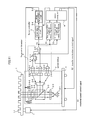
- FIG. 1 is a first block diagram of an optical disk apparatus installed a focal control adjusting method in a preferred embodiment 1 of the present invention.
- FIGS. 2A-2C are a relation diagram of a focal error signal to a relative position between an irradiating position of a light beam spot and a disk recording surface in the preferred embodiment 1.
- FIG. 3 is a flow chart of a first focal control adjusting method according to the preferred embodiment 1.
- FIG. 4 is a second block diagram of the optical disk apparatus installed the focal control adjusting method according to the preferred embodiment 1.
- FIG. 5 is a flow chart of a second focal control adjusting method according to the preferred embodiment 1.
- FIG. 6 is a flow chart of a third focal control adjusting method according to the preferred embodiment 1.
- FIG. 7 is a flow chart of a fourth focal control adjusting method according to the preferred embodiment 1.
- FIG. 8 is a flow chart of a fifth focal control adjusting method according to the preferred embodiment 1.
- FIG. 9 is a flow chart of a sixth focal control adjusting method according to the preferred embodiment 1.
- FIG. 10 is a third block diagram of the optical disk apparatus installed the focal control adjusting method according to the preferred embodiment 1.
- FIG. 11 is a first block diagram of an optical disk apparatus installed a focal control adjusting method according to a preferred embodiment 2 of the present invention.
- FIG. 12 is a relation diagram between a relative position from a current position to a objective position in a transfer mechanism and a moving speed of the transfer mechanism controlled by a microcomputer according to the preferred embodiment 2.
- FIG. 13 is a flow chart of a focal control adjusting method according to the preferred embodiment 2.
- FIG. 14 is a second block diagram of the optical disk apparatus installed the focal control adjusting method according to the preferred embodiment 2.
- FIG. 15 is a third block diagram of the optical disk apparatus installed the focal control adjusting method according to the preferred embodiment 2.
- FIG. 16 is a diagram of a structure of the components in an optical pickup according to a conventional technology.
- FIG. 1 is a block diagram illustrating an example of structure with respect to an optical disk apparatus in which a focal control adjusting method according to a preferred embodiment 1 of the present invention is conducted.
- a DVD-RAM disk which is an example of a recording medium (hereinafter, referred to as disk) 1
- a motor 3 rotates the disk 1 .
- the motor 3 is controlled in accordance with a rotational speed control signal S 1 outputted from a microcomputer 9 .
- a light source 2 - 1 is an element for emitting a light beam of, for example, 650 nm.
- the light beam emitted from the light source 2 - 1 enters a diffraction grating 2 - 2 so as to be divided therein into at least three light beams, which are a main light beam transmitting just through the diffraction grating 2 - 2 (zero-order light) and two sub light beams progressing separately from the main light beam at a predetermined diffraction angle (positive first-order diffracted light and negative first-order diffracted light).
- These three light beams enters a collimate lens 2 - 4 via a polarized beam splitter 2 - 3 , converted into parallel lights in the collimate lens 2 - 4 , and condensed on a recording surface of the recording medium (hereinafter, referred to as disk) 1 such as DVD-RAM via an object lens 2 - 5 .
- the condensed light beams form three light beam spots on the recording surface.
- the condensed light beams are reflected on the disk 1 and turn into a reflected light (return light) traveling a same optical path as that of an irradiated light (outgoing light), and is reflected on a reflecting surface of the polarized beam splitter 2 - 3 via the object lens 2 - 5 and the collimate lens 2 - 4 .
- the reflected light is condensed on predetermined light receipt surfaces of light detectors 2 - 7 , 2 - 8 - 1 and 2 - 8 - 2 via a condensing lens 2 - 6 .
- the main light beam of the reflected light is condensed on the light detector 2 - 7 , and the two sub light beams (positive first-order diffracted light and negative first-order diffracted light) of the reflected light are condensed on the light detectors 2 - 8 - 1 and 2 - 8 - 2 .
- the main light beam is condensed on a substantially central position of a light receipt region.
- the sub light beams (positive first-order diffracted light and negative first-order diffracted light) are condensed respectively on positions at which the centers of their intensity are substantially identical.
- a focal error signal based on the astigmatic focal error detection is detected in the light detectors 2 - 7 , 2 - 8 - 1 and 2 - 8 - 2 .
- the object lens 2 - 5 is provided with two-dimensional actuators 2 - 9 - 1 and 2 - 9 - 2 .
- An optical pickup 2 comprises the light source 2 - 1 , diffraction grating 2 - 2 , polarized beam splitter 2 - 3 , collimate lens 2 - 4 , object lens 2 - 5 , condensing lens 2 - 6 , light detectors 2 - 7 , 2 - 8 - 1 and 2 - 8 - 2 , and two-dimensional actuators 2 - 9 - 1 and 2 - 9 - 2 .
- the outputs from the light detectors 2 - 7 , 2 - 8 - 1 and 2 - 8 - 2 are inputted to a first differential circuit 4 - 1 , a first adding circuit 4 - 2 - 1 and a second adding circuit 4 - 2 - 2 .
- the first differential circuit 4 - 1 detects an intensity difference of the main light beams (reflected light) and generates a position detection signal (main light beam) based on the main light beam.
- the position detection signal (main light beam) is referred to as a main focal error signal ME.
- the main focal error signal MFE is inputted to a third adding circuit 4 - 5 .
- the first and second adding circuits 4 - 2 - 1 and 4 - 2 - 2 add the outputs of the light detectors 2 - 8 - 1 and 2 - 8 - 2 respectively and output it to a second differential circuit 4 - 3 .
- the additions by the first and second adding circuits 4 - 2 - 1 and 4 - 2 - 2 are carried out in order to detect intensity differences of the respective sub light beams (reflected lights)
- the second differential circuit 4 - 3 detects the intensity differences of the sub light beams (reflected lights) based on the outputs of the first adding circuit 4 - 2 - 1 and the second adding circuit 4 - 2 - 2 and generates position detection signal (sub light beams) based on the sub light beams from a result of the detection.
- the position detection signal (sub light beams) is referred to as a sub focal error signal SFE.
- the sub focal error signal SFE is inputted to a multiplying circuit 4 - 4 , where the sub focal, error signal SFE is multiplied by a predetermined coefficient k.
- the sub focal error signal SFE multiplied by the coefficient k is inputted to the third adding circuit 4 - 5 .
- the third adding circuit 4 - 5 adds the output of the first differential circuit 4 - 1 and the output of the multiplying circuit 4 - 4 to each other to thereby generate the focal error signal FE.
- a focal error detector 4 comprises the first differential circuit 4 - 1 , first adding circuit 4 - 2 - 1 , second adding circuit 4 - 2 - 2 , second differential circuit 4 - 3 , multiplying circuit 4 - 4 , and third adding circuit 4 - 5 .
- FIGS. 2A-2C respectively illustrate the focal error signals detected from the reflected lights of light beam spots 100 , 101 and 102 , wherein a signal amplitude is shown in a vertical axis and a relative position between an irradiating position and the recording surface of the disk 1 is shown in a horizontal axis.
- a signal amplitude is shown in a vertical axis
- a relative position between an irradiating position and the recording surface of the disk 1 is shown in a horizontal axis.
- the two signals are in-phase, while the phases of the disturbance components generated in the signals are inverse each other.
- the focal controller 5 carries out automatic positional adjustment, namely, focal control with respect to the object lens 2 - 5 based on the focal error signal FE supplied from the third adding circuit 4 - 5 , and precisely makes the light beam spot irradiated on the recording surface of the disk 1 .
- the focal controller 5 comprises a phase delay compensating circuit 5 - 1 and a phase advancement compensating circuit 5 - 2 , wherein gains of the respective circuits are made variable.
- the focal error signal FE is also inputted to a first measurement device for an amplitude of focal error 6 , a second measurement device for an amplitude of focal error 7 , and a first measurement device for focal error cycle 8 .
- the first measurement device for an amplitude of focal error 6 and the second measurement device for an amplitude of focal error 7 measure an amplitude of the focal error signal FE from a maximum value and a minimum value of the focal error signal FE in a predetermined interval and outputs a result of the measurement to the microcomputer 9 .
- the first measurement device for focal error cycle 8 measures a maximum cycle and a minimum cycle of the focal error signal FE in a predetermined interval and calculates an average value of the cycles, and outputs a result of the calculation to the microcomputer 9 .
- the microcomputer 9 determines the gain of the multiplying circuit 4 - 4 , that is the coefficient k in the equation (1), based on the measurement result of the first measurement device for an amplitude of focal error 6 , and sets the determined coefficient (gain) k in the multiplying circuit 4 - 4 .
- the microcomputer 9 determines a focal control gain based on the measurement result of the second measurement device for an amplitude of focal error 7 and sets the determined focal control gain in the focal controller 5 . Further, the microcomputer 9 determines and sets a rotational speed of the motor 3 based on the measurement result of the first measurement device for focal error cycle 8 .
- FIG. 3 is a flow chart of an example of the focal control adjusting method according to the preferred embodiment 1.
- the gain k is adjusted in the multiplying circuit 4 - 4 that controls the most effectively the influence of the disturbance resulting from the leaked-in push-pull signal superposed on the focal error signal FE.
- a focal control loop is closed in a state where an arbitrary value is set as the coefficient k of the multiplying circuit 4 - 4 (STEP 1 - 1 ).
- the first measurement device for an amplitude of focal error 6 measures the amplitude of the focal error signal FE from the maximum and minimum values thereof, and outputs the measured amplitude to the microcomputer 9 (STEP 1 - 2 ).
- the microcomputer 9 memorizes the measurement result of the first measurement device for an amplitude of focal error 6 and updates the coefficient k of the multiplying circuit 4 - 4 (STEP 1 - 3 ).
- the following steps are carried out in order to control the deterioration of the focal control performance even when the disturbance due to the leaked-in push-pull signal is superposed on the focal error signal FE.
- the second measurement device for an amplitude of focal error 7 measures the amplitude of the focal error signal FE based on the maximum and minimum values thereof and outputs the measurement result to the microcomputer 9 (STEP 2 - 1 ).
- ⁇ is an arbitrary coefficient
- the focal control gain FCG is adjusted so as to be inversely proportional to the output Amp 2 of the second measurement device for an amplitude of focal error 7 .
- the executed focal control can be stabilized without supplying any excessively large drive signal to the two-dimensional actuators 2 - 9 - 1 and 2 - 9 - 2 because of the implementation of the STEP 2 - 1 and the STEP 2 - 2 , however, there is some danger that a residual suppression performance of the focal control may be deteriorated in case that the focal control gain FCG is adjusted to be any value equal to or lower than an appropriate value.
- the limit value may be set as the focal control gain FCG.
- the gain adjusting method for the focal controller 5 described in the present preferred embodiment is only an example.
- the microcomputer 9 may retain at least two set values as the focal control gain FCG to be set in the focal controller 5 , wherein one of the set values may be set in order to switch them depending on the output level of the second measurement device for an amplitude of focal error 7 .
- the focal controller 5 may be consisted of the phase delay compensating circuit 5 - 1 and the phase advancement compensating circuit 5 - 2 , the microcomputer 9 may adjust only the gain of the phase advancement compensating circuit 5 - 2 .
- the first measurement device for focal error cycle 8 may measure the cycle of the focal error signal FE and adjust the gain of the focal controller 5 or the phase advancement compensating circuit 5 - 2 based on a minimum value, an average value or a maximum value of the measured cycle.
- the microcomputer 9 may memorize a gain characteristic of the focal controller 5 per cycle of the cycle and adjust the gain characteristic so that the gain in the minimum value, average value or maximum value of the cycle of the focal error signal FE measured by the first measurement device for focal error cycle 8 corresponds to the gain characteristic memorized by the microcomputer 9 .
- the gain characteristic is adjusted in the STEP 1 - 2 based on the amplitude of the focal error signal FE measured by the first measurement device for an amplitude of focal error 6 .
- the focal control gain FCG can be appropriately adjusted even in the case where the disturbance due to the leaked-in push-pull signal is superposed on the focal error signal FE.
- the focal control can be stably realized without supplying any excessively large drive signal to the two-dimensional actuators 2 - 9 - 1 and 2 - 9 - 2 .
- the focal control can be stably realized without supplying any excessively large drive signal to the two-dimensional actuators 2 - 9 - 1 and 2 - 9 - 2 .
- the conduction of these steps may not obtain a sufficient effect. Therefore, after the focal control gain FCG is calculated based on the equation (2) and adjusted, the second measurement device for an amplitude of focal error 7 measures the amplitude of the focal error signal FE based on the maximum and minimum values thereof again, and outputs the measurement result to the microcomputer 9 (STEP 2 - 3 ).
- the microcomputer 9 compares the measurement result of the second measurement device for an amplitude of focal error 7 to a predetermined value previously retained by the microcomputer 9 , determines the rotational speed (double speed) of the motor 3 based on a result of the comparison, and outputs the rotational speed control signal S 1 indicating the determined rotational speed to the motor 3 .
- the motor 3 controls the rotation of the disk 1 to rotate at a predetermined rotation frequency in accordance with the rotational speed control signal S 1 (STEP 2 - 4 ).
- a disturbance frequency d f due to the leaked-in push-pull signal superposed on the focal error signal FE is in proportion to an eccentricity x dec of the disk 1 and a rotational speed v mt of the motor 3 as shown in following the equation (4).
- the focal controller 5 comprises the phase delay compensating circuit 5 - 1 and the phase advancement compensating circuit 5 - 2 .
- the phase advancement compensating circuit 5 - 2 amplifies the disturbance due to the leaked-in push-pull signal superposed on the focal error signal FE in accordance with the disturbance frequency d f , which may excessively increases the output of the focal controller 5 .
- the rotational speed of the motor 3 can be appropriately adjusted even in the case where the disturbance due to the leaked-in push-pull signal is superposed on the focal error signal FE.
- the focal control can be stably realized without excessively increasing the output of the focal controller 5 .
- FIG. 4 shows a modified embodiment of the optical disk apparatus according to the preferred embodiment 1 shown in FIG. 1 .
- the first measurement device for an amplitude of focal error 6 is replaced with a focal control drive measurement device 14 in the construction of FIG. 1 .
- the focal control drive measurement device 14 to which the output of the focal controller 5 is inputted to, is provided with a function for measuring drive signals to the two-dimensional actuators 2 - 9 - 1 and 2 - 9 - 2 in a predetermined interval.
- An output of the focal control drive measurement device 14 is connected to the microcomputer 9 .
- the microcomputer 9 determines the gain of the multiplying circuit 4 - 4 , that is the coefficient k in the equation (1), based on a result of the measurement by the measurement device for driving focal control 14 , and sets the determined coefficient k to the multiplying circuit 4 - 4 .
- FIG. 5 is a flow chart obtained by changing the STEP 1 - 2 in the first step in the focal control adjusting method according to the preferred embodiment 1 (flow chart of FIG. 3 ). More specifically, in the first step in FIG. 3 , the first measurement device for an amplitude of focal error 6 measures the amplitude of the focal error signal FE based on the maximum and minimum values thereof, and outputs the measurement result to the microcomputer 9 .
- the microcomputer 9 memorizes the measurement result of the first measurement device for an amplitude of focal error 6 , and updates the coefficient k of the multiplying circuit 4 - 4 based on a result obtained by comparing the last measurement result of the measuring device 6 and the current measurement result of the measuring device 6 .
- the updating processing is repeatedly executed.
- the output of the focal controller 5 that is a focal control drive signal, is measured and outputted to the microcomputer 9 .
- the microcomputer 9 repeatedly updates the coefficient k of the multiplying circuit 4 - 4 based on the focal control drive signal measured by the measurement device for driving focal control 14 until the focal control drive signal is reduced to minimum.
- the influence caused on the focal control drive signal by the disturbance due to the leaked-in push-pull signal superposed on the focal error signal FE can be minimized.
- the first step, 2 - 1 step and 2 - 2 step are carried out in that order referring to FIGS. 1 and 3 .
- the 2 - 2 step and the 2 - 1 step may be carried out in that order after the first step is implemented as shown in FIG. 6 in stead of FIG. 3 , it is obvious to exert a similar effect.
- the first step, 2 - 1 step and 2 - 2 step are all conducted.
- only the 2 - 1 step may be carried out after the first step is conducted as shown in FIG. 7 instead of FIG. 3 .
- the focal control can be stably realized without excessively increasing the output of the focal controller 5 .
- only the 2 - 2 step may be carried out after the first step is conducted as shown in FIG. 8 instead of FIG. 3 .
- the focal control can be stably realized without excessively increasing the output of the focal controller 5 .
- the focal control can be stably realized without excessively increasing the output of the focal controller 5 by conducting the 2 - 1 step and/or the 2 - 2 step. Further, a processing time for conducting the first step can be reduced.
- switchers 10 - 1 and 10 - 2 may be provided so that any of the focal error signal FE, position detection signal MFE and position detection signal SFE can be selected as the input signals of the second measurement device for an amplitude of focal error 7 and the first measurement device for focal error cycle 8 .
- the amplitude or the cycle of the focal error signal FE detected in the STEP 2 - 1 and the STEP 2 - 3 may correspond to the amplitude or the cycle of the position detection signal MFE and the amplitude or the cycle of the position detection signal SFE, in which case a similar effect can be obtained.
- the focal control gain FCG and the rotational speed of the motor 3 adjusted in the 2 - 1 step and the 2 - 2 step can be applied only when the tracking control loop is open, so that the focal control performance of the optical disk apparatus can be improved.
- the tracking control loop When the tracking control loop is closed in the case of reproducing or recoding information with respect to the disk 1 , the disturbance due to the leaked-in push-pull signal does not affect the focal error signal FE because the light beam spot is controlled on the track 1 - 1 . Therefore, when the tracking control loop is closed, the focal control gain FCG and the rotational speed of the motor 3 determined in the 2 - 1 step and the 2 - 2 step are not applied, but the focal control gain is increased to control a surface wobbling component of the disk 1 , or the rotational speed of the motor 3 is increased to reproduce or record the information at a higher speed. Thereby, the performance of the optical disk apparatus can be improved.
- the rotational speed of the motor 3 may be determined based on the measurement result of the first measurement device for focal error cycle 8 .
- FIG. 11 is a block diagram illustrating an example of an optical disk apparatus in which a focal control adjusting method according to a preferred embodiment 2 of the present invention is installed.
- the reference numerals shown in FIG. 11 corresponding to those shown in FIG. 1 denote the same components, which are, therefore, not described in detail again.
- a reference numeral 11 denotes a transfer mechanism for moving the optical pickup 2 to an arbitrary position in direction to traverse the track 1 - 1 of the disk 1 .
- the transfer mechanism 11 can move the object lens 2 - 5 , which is a component of the optical pickup 2 , to the arbitrary position in direction to traverse the track 1 - 1 .
- the transfer mechanism 11 can also move the light beam spot to an arbitrary position in direction to traverse the track 1 - 1 .
- the transfer mechanism 11 is position-controlled based on a transfer mechanism control signal S 2 supplied from the microcomputer 9 .
- a reference numeral 12 denotes a third measurement device for an amplitude of focal error to measure the amplitude of the focal error signal FE from the maximum and minimum values thereof and outputting the measurement result to the microcomputer 9 as Amp 3 .
- FIG. 12 shows a characteristic of the transfer mechanism control signal S 2 outputted from the microcomputer 9 to the transfer mechanism 11 , wherein a moving speed by the transfer mechanism 11 is plotted in a vertical axis, and a position of the transfer mechanism 11 is plotted in a horizontal axis.
- the microcomputer 9 outputs the transfer mechanism control signal S 2 in accordance with a profile shown in FIG. 12 based on a current position and an objective position of the transfer mechanism 11 .
- a value of the transfer mechanism control signal S 2 is adjusted in the microcomputer 9 so that a moving speed of the beam condensing spot is increased.
- the value of the transfer mechanism control signal S 2 is adjusted so that a moving speed v reaches a maximum speed vmax as a uniform rate when the beam condensing spot reaches a position x 1 .
- the value of the transfer mechanism control signal S 2 is adjusted so that the moving speed by the transfer mechanism 11 is reduced.
- the value of transfer mechanism control signal S 2 is adjusted so that the moving speed is further reduced.
- Such a control mode is applied in a similar manner when an initial position of the transfer mechanism 11 changes as shown by x 1 in FIG. 12 .
- the value of the transfer mechanism control signal S 2 is adjusted so that the moving speed is reduced.
- the preferred embodiment 2 is characterized in that, by further conducting the STEP 1 - 1 and the STEP 1 - 2 in the construction according to the preferred embodiment 1 so that the maximum speed vmax of the transfer mechanism control signal S 2 outputted to the transfer mechanism 11 is restricted by the microcomputer 9 in accordance with the amplitude or frequency of the disturbance due to the leaked-in push-pull signal superposed on the focal error signal FE in a state where the disturbance is adjusted.
- FIG. 13 is a flow chart of an example of the focal control adjusting method according to the preferred embodiment 1.
- the gain (coefficient) k of the multiplying circuit 4 - 4 is adjusted to such a value that the influence of the disturbance due to the leaked-in push-pull signal superposed on the focal error signal FE is controlled at the lowest level.
- the focal control loop is closed in a state where an arbitrary value is set as the gain (coefficient) k of the multiplying circuit 4 - 4 (STEP 1 - 1 ).
- the first measurement device for an amplitude of focal error 6 measures the amplitude of the focal error signal FE from the maximum and minimum values thereof and outputs the measurement result to the microcomputer 9 (STEP 1 - 2 ).
- the microcomputer 9 memorizes the measurement result of the first measurement device for an amplitude of focal error 6 , and updates the coefficient k of the multiplying circuit 4 - 4 based on the comparison result obtained by comparing the last measurement result of the measuring device 6 and the current measurement result of the measuring device 6 .
- the updating processing is repeatedly executed so that the coefficient k of the multiplying circuit 4 - 4 is adjusted in such a manner that the output of the first measurement device for an amplitude of focal error 6 is minimized.
- the maximum speed vmax of the transfer mechanism control signal S 2 is adjusted.
- the third measurement device for an amplitude of focal error 12 measures the amplitude of the focal error signal FE based on the maximum and minimum values thereof, and outputs the measurement result Amp 3 to the microcomputer 9 (STEP 2 - 1 ′). Then, the microcomputer 9 calculates the maximum speed vmax of the transfer mechanism control signal S 2 using the measurement result Amp 3 based on the following equation (5).
- v max v max0 ⁇ ( ⁇ / Amp 3) (5)
- ⁇ is an arbitrary coefficient
- the maximum speed vmax of the transfer mechanism control signal S 2 is adjusted to be inversely proportional to the measurement result Amp 3 (STEP 2 - 2 ′).
- An adjustment processing similar to the adjustment processing described above can be executed in the case where a second measurement device for focal error cycle 13 is adopted in place of the third measurement device for an amplitude of focal error 12 as shown in FIG. 14 .
- a control method to use the second measurement device for focal error cycle 13 is given.
- the second measurement device for focal error cycle 13 measures the cycle of the focal error signal FE and output the measured cycle to the microcomputer 9 .
- the microcomputer 9 memorizes the measurement result of the second measurement device for focal error cycle 13 and updates the coefficient k of the multiplying circuit 4 - 4 based on the result obtained by comparing the last measurement result of the measuring device 13 to the current measurement result of the measuring device 13 .
- the updating processing is repeatedly executed so that the coefficient k of the multiplying circuit 4 - 4 is adjusted in such a manner that the output of the first measurement device for an amplitude of focal error 6 is minimized.
- the maximum value, minimum value or average value of the cycle of the focal error signal FE is measured and outputted to the microcomputer 9 .
- the microcomputer 9 detects the minimum value of the cycle of the focal error signal FE as the output of the second measurement device for focal error cycle 13 to thereby detect an eccentric maximum speed of the disk 1 .
- the microcomputer 9 controls the speed of the transfer mechanism 11 so that a sum of the eccentric speed of the disk 1 and the speed at which the light beam traverses the track 1 - 1 corresponds to a predetermined speed.
- the microcomputer 9 may adjust the moving speed by the transfer mechanism 11 based on the output of the third measurement device for an amplitude of focal error 12 and the output of the second measurement device for focal error cycle 13 , the control precision can be further improved by doing so.
- the moving speed by the transfer mechanism 11 is adjusted as described in accordance with the measurement result of the second measurement device for focal error cycle 13 only when the measurement result of the third measurement device for an amplitude of focal error 12 is equal to or higher than a predetermined value. Accordingly, not only an accessing time for reproducing or recording the information of the disk 1 can reduced but also the focal control can be stabilized.
- the 2 - 1 step′ (STEP 2 - 1 ′-STEP 2 - 2 ′) is carried out after the first step (STEP 1 - 1 -STEP 1 - 3 ) is done
- one of the 2 - 1 step and the 2 - 2 step may be conducted after the first step is carried out as in the preferred embodiment 1, followed by the conduction of the 2 - 1 step′, even in which case a similar effect can be obviously obtained.
- the STEP 2 - 2 ′ and steps thereafter may be omitted in accordance with the measurement result of the third measurement device for an amplitude of focal error 12 or the measurement result of the second measurement device for focal error cycle 13 obtained when the STEP 2 - 1 ′ is done.
- the focal error signal FE is inputted to the third measurement device for an amplitude of focal error 12 and the second measurement device for focal error cycle 13 as shown in FIGS. 11 , 14 and 15 , but the position detection signal MFE and the position detection signals SFE may be inputted to these measuring devices 12 and 13 , though not shown, in which case a similar effect can be obtained.
- the first measurement device for an amplitude of focal error 6 measures the amplitude of the focal error signal FE in order to determine the coefficient k of the multiplying circuit 4 - 4 as shown in FIGS. 10 , 11 , 14 and 15 .
- the measurement device for driving focal control 14 may measure the output of the focal controller 5 (see FIG. 4 ), and may determine the coefficient k of the multiplying circuit 4 - 4 based on the obtained measurement result, in which case a similar effect can be obtained.
Landscapes
- Optical Recording Or Reproduction (AREA)
- Rotational Drive Of Disk (AREA)
- Moving Of The Head For Recording And Reproducing By Optical Means (AREA)
Abstract
Description
-
- after three beam condensing spots are formed on the rotating recording medium by condensing and irradiating the light beam consisting of a main light beam and two sub light beams to the recording medium, a position detection signal (main light beam) indicating a position of the beam condensing spot in the main light beam is generated based on a main reflected light obtained through reflection of the main light beam on the recording medium, and position detection signal (sub light beams) indicating position of the beam condensing spot in the sub light beams are generated based on two sub reflected lights obtained through reflection of the sub light beams on the recording medium and having different phases from that of the main reflected light in the first step, and
FE=A+k×B
FE=MFE+k×SFE (1)
FCG=FCG0×(α/Amp2) (2)
α=FCGref×Amp2/FCG0 (3)
df∝(xdec,vmt) (4)
vmax=vmax0×(β/Amp3) (5)
Claims (27)
Applications Claiming Priority (4)
| Application Number | Priority Date | Filing Date | Title |
|---|---|---|---|
| JP2005-132662 | 2005-04-28 | ||
| JP2005132662 | 2005-04-28 | ||
| JP2006108530A JP4551883B2 (en) | 2005-04-28 | 2006-04-11 | Focus control adjustment method and optical disc apparatus |
| JP2006-108530 | 2006-04-11 |
Publications (2)
| Publication Number | Publication Date |
|---|---|
| US20060262678A1 US20060262678A1 (en) | 2006-11-23 |
| US7768882B2 true US7768882B2 (en) | 2010-08-03 |
Family
ID=37448197
Family Applications (1)
| Application Number | Title | Priority Date | Filing Date |
|---|---|---|---|
| US11/413,121 Expired - Fee Related US7768882B2 (en) | 2005-04-28 | 2006-04-28 | Focal control adjusting method and optical disk apparatus |
Country Status (4)
| Country | Link |
|---|---|
| US (1) | US7768882B2 (en) |
| JP (1) | JP4551883B2 (en) |
| KR (1) | KR20060113542A (en) |
| TW (1) | TW200641855A (en) |
Families Citing this family (1)
| Publication number | Priority date | Publication date | Assignee | Title |
|---|---|---|---|---|
| CN107267950A (en) * | 2017-04-25 | 2017-10-20 | 苏州同冠微电子有限公司 | A kind of evaporator beam spot remote-control box and its control method |
Citations (12)
| Publication number | Priority date | Publication date | Assignee | Title |
|---|---|---|---|---|
| JPH04134729A (en) | 1990-09-27 | 1992-05-08 | Internatl Business Mach Corp <Ibm> | Optical disc driver |
| JPH0981942A (en) | 1995-09-08 | 1997-03-28 | Mitsubishi Electric Corp | Optical head tracking error detector |
| JP2000082226A (en) | 1998-07-03 | 2000-03-21 | Hitachi Ltd | Photodetector, signal processing circuit, and optical information reproducing apparatus using the same |
| JP2003157547A (en) | 2001-11-22 | 2003-05-30 | Sharp Corp | Servo device |
| JP2003228846A (en) | 2002-01-30 | 2003-08-15 | Hitachi-Lg Data Storage Inc | Optical disk apparatus and optical disk reproducing method |
| WO2004102546A1 (en) | 2003-05-16 | 2004-11-25 | Thomson Licensing | Method and device for adjusting an amplification for producing a focus error signal |
| JP2005085397A (en) | 2003-09-10 | 2005-03-31 | Hitachi-Lg Data Storage Inc | Optical disk device and method for controlling optical disk device |
| US6928034B2 (en) * | 2000-12-20 | 2005-08-09 | Sony Computer Entertainment Inc. | Optical disc apparatus and method for adjusting a servo of same |
| US20060028945A1 (en) * | 2004-07-13 | 2006-02-09 | Micro-Star International Co., Ltd. | Method and device for disc rotation control in an optical storage system based on detected extent of disc warping |
| US20060104173A1 (en) * | 2004-11-16 | 2006-05-18 | Tdk Corporation | Method of detecting focus error signal of optical head and optical head and optical recording/reproducing apparatus utilizing the same |
| US7057982B2 (en) * | 2002-01-10 | 2006-06-06 | Texas Instruments Incorporated | Servo error detector for optical disk |
| US7142484B2 (en) * | 2000-11-24 | 2006-11-28 | Kabushiki Kaisha Toshiba | Optical information processing system using optical aberrations and information medium having recording layer protected by transparent layer having thickness irregularity |
Family Cites Families (2)
| Publication number | Priority date | Publication date | Assignee | Title |
|---|---|---|---|---|
| JP2001126273A (en) * | 1999-10-25 | 2001-05-11 | Nec Corp | Focus error signal detection method and optical disk head device for land/groove recording/reproduction |
| JP2003217142A (en) * | 2002-01-22 | 2003-07-31 | Nec Corp | Method for detecting optical disk focus error and optical disk apparatus |
-
2006
- 2006-04-11 JP JP2006108530A patent/JP4551883B2/en not_active Expired - Fee Related
- 2006-04-26 TW TW095114839A patent/TW200641855A/en unknown
- 2006-04-28 US US11/413,121 patent/US7768882B2/en not_active Expired - Fee Related
- 2006-04-28 KR KR1020060038738A patent/KR20060113542A/en not_active Ceased
Patent Citations (12)
| Publication number | Priority date | Publication date | Assignee | Title |
|---|---|---|---|---|
| JPH04134729A (en) | 1990-09-27 | 1992-05-08 | Internatl Business Mach Corp <Ibm> | Optical disc driver |
| JPH0981942A (en) | 1995-09-08 | 1997-03-28 | Mitsubishi Electric Corp | Optical head tracking error detector |
| JP2000082226A (en) | 1998-07-03 | 2000-03-21 | Hitachi Ltd | Photodetector, signal processing circuit, and optical information reproducing apparatus using the same |
| US7142484B2 (en) * | 2000-11-24 | 2006-11-28 | Kabushiki Kaisha Toshiba | Optical information processing system using optical aberrations and information medium having recording layer protected by transparent layer having thickness irregularity |
| US6928034B2 (en) * | 2000-12-20 | 2005-08-09 | Sony Computer Entertainment Inc. | Optical disc apparatus and method for adjusting a servo of same |
| JP2003157547A (en) | 2001-11-22 | 2003-05-30 | Sharp Corp | Servo device |
| US7057982B2 (en) * | 2002-01-10 | 2006-06-06 | Texas Instruments Incorporated | Servo error detector for optical disk |
| JP2003228846A (en) | 2002-01-30 | 2003-08-15 | Hitachi-Lg Data Storage Inc | Optical disk apparatus and optical disk reproducing method |
| WO2004102546A1 (en) | 2003-05-16 | 2004-11-25 | Thomson Licensing | Method and device for adjusting an amplification for producing a focus error signal |
| JP2005085397A (en) | 2003-09-10 | 2005-03-31 | Hitachi-Lg Data Storage Inc | Optical disk device and method for controlling optical disk device |
| US20060028945A1 (en) * | 2004-07-13 | 2006-02-09 | Micro-Star International Co., Ltd. | Method and device for disc rotation control in an optical storage system based on detected extent of disc warping |
| US20060104173A1 (en) * | 2004-11-16 | 2006-05-18 | Tdk Corporation | Method of detecting focus error signal of optical head and optical head and optical recording/reproducing apparatus utilizing the same |
Non-Patent Citations (1)
| Title |
|---|
| Japanese Office Action issued in Japanese Patent Application No. JP 2006-108530 dated Dec. 8, 2009. |
Also Published As
| Publication number | Publication date |
|---|---|
| KR20060113542A (en) | 2006-11-02 |
| JP2006331616A (en) | 2006-12-07 |
| US20060262678A1 (en) | 2006-11-23 |
| TW200641855A (en) | 2006-12-01 |
| JP4551883B2 (en) | 2010-09-29 |
Similar Documents
| Publication | Publication Date | Title |
|---|---|---|
| JPH02206033A (en) | Tracking error detector for optical disk device | |
| KR100601632B1 (en) | Error signal detection device for optical recorder | |
| JP2004519806A (en) | Tilt control device and method | |
| US7187632B2 (en) | Optical disk device and method of adjusting tilt control amount | |
| US7768882B2 (en) | Focal control adjusting method and optical disk apparatus | |
| US20060098540A1 (en) | Optical information recording/reproducing apparatus comprising spherical aberration mechanism | |
| CN104350543B (en) | Optical disc information device and information processing device | |
| US20040136282A1 (en) | Method for calibrating center error offset in an optical drive and control system capable of calibrating center error offset | |
| KR100189911B1 (en) | Servo device of optical disk drive and its control method | |
| KR100489544B1 (en) | Optical disk device | |
| CN100505051C (en) | Focus control adjustment method and optical disc device | |
| JP2005310257A (en) | Optical disk device | |
| US7248545B2 (en) | Optical pickup device | |
| KR100722591B1 (en) | Method for compensating a error swerved from optical axis in optical pick up | |
| JP2006521646A (en) | Method and apparatus for measuring the tilt of an optical disc | |
| US8675459B2 (en) | Optical disk apparatus | |
| US8154959B2 (en) | Optical storage system and spherical aberration compensation apparatus and method thereof | |
| JPH10177727A (en) | Tracking error signal generation circuit | |
| JP2007502487A (en) | Disk drive device | |
| JP2006196121A (en) | Optical information recording / reproducing apparatus | |
| JPH10149550A (en) | Optical disk drive | |
| US20080037389A1 (en) | Method for determining track searching direction | |
| JPH07235064A (en) | Method for automatically balance adjusting position senser and circuit therefor | |
| JP2006260706A (en) | Optical information recording / reproducing method | |
| KR19980048653A (en) | Pit Depth Correction Method of Optical Disc System |
Legal Events
| Date | Code | Title | Description |
|---|---|---|---|
| AS | Assignment |
Owner name: MATSUSHITA ELECTRIC INDUSTRIAL CO., LTD., JAPAN Free format text: ASSIGNMENT OF ASSIGNORS INTEREST;ASSIGNOR:KUWAHARA, MASAYA;REEL/FRAME:018240/0105 Effective date: 20060511 |
|
| AS | Assignment |
Owner name: PANASONIC CORPORATION, JAPAN Free format text: CHANGE OF NAME;ASSIGNOR:MATSUSHITA ELECTRIC INDUSTRIAL CO., LTD.;REEL/FRAME:021897/0671 Effective date: 20081001 Owner name: PANASONIC CORPORATION,JAPAN Free format text: CHANGE OF NAME;ASSIGNOR:MATSUSHITA ELECTRIC INDUSTRIAL CO., LTD.;REEL/FRAME:021897/0671 Effective date: 20081001 |
|
| FEPP | Fee payment procedure |
Free format text: PAYOR NUMBER ASSIGNED (ORIGINAL EVENT CODE: ASPN); ENTITY STATUS OF PATENT OWNER: LARGE ENTITY |
|
| FPAY | Fee payment |
Year of fee payment: 4 |
|
| SULP | Surcharge for late payment | ||
| AS | Assignment |
Owner name: SOCIONEXT INC., JAPAN Free format text: ASSIGNMENT OF ASSIGNORS INTEREST;ASSIGNOR:PANASONIC CORPORATION;REEL/FRAME:035294/0942 Effective date: 20150302 |
|
| FEPP | Fee payment procedure |
Free format text: MAINTENANCE FEE REMINDER MAILED (ORIGINAL EVENT CODE: REM.) |
|
| LAPS | Lapse for failure to pay maintenance fees |
Free format text: PATENT EXPIRED FOR FAILURE TO PAY MAINTENANCE FEES (ORIGINAL EVENT CODE: EXP.); ENTITY STATUS OF PATENT OWNER: LARGE ENTITY |
|
| STCH | Information on status: patent discontinuation |
Free format text: PATENT EXPIRED DUE TO NONPAYMENT OF MAINTENANCE FEES UNDER 37 CFR 1.362 |
|
| FP | Lapsed due to failure to pay maintenance fee |
Effective date: 20180803 |