US7761634B2 - Method, device and system for exchanging data via a bus system - Google Patents
Method, device and system for exchanging data via a bus system Download PDFInfo
- Publication number
- US7761634B2 US7761634B2 US10/560,959 US56095905A US7761634B2 US 7761634 B2 US7761634 B2 US 7761634B2 US 56095905 A US56095905 A US 56095905A US 7761634 B2 US7761634 B2 US 7761634B2
- Authority
- US
- United States
- Prior art keywords
- time
- pause period
- cycle
- duration
- basic
- Prior art date
- Legal status (The legal status is an assumption and is not a legal conclusion. Google has not performed a legal analysis and makes no representation as to the accuracy of the status listed.)
- Expired - Lifetime
Links
- 238000000034 method Methods 0.000 title claims abstract description 16
- 230000006978 adaptation Effects 0.000 claims abstract description 9
- 230000008859 change Effects 0.000 claims abstract description 7
- 238000012937 correction Methods 0.000 claims description 41
- 238000004904 shortening Methods 0.000 claims description 9
- 230000001360 synchronised effect Effects 0.000 claims description 8
- 238000004891 communication Methods 0.000 description 24
- 230000005540 biological transmission Effects 0.000 description 12
- 230000001960 triggered effect Effects 0.000 description 12
- 239000011159 matrix material Substances 0.000 description 7
- 230000002950 deficient Effects 0.000 description 6
- 230000000694 effects Effects 0.000 description 6
- 230000000737 periodic effect Effects 0.000 description 6
- 230000001934 delay Effects 0.000 description 5
- 238000009826 distribution Methods 0.000 description 4
- 238000013459 approach Methods 0.000 description 3
- 230000008901 benefit Effects 0.000 description 2
- 230000001419 dependent effect Effects 0.000 description 2
- 238000005259 measurement Methods 0.000 description 2
- 230000002269 spontaneous effect Effects 0.000 description 2
- 230000009471 action Effects 0.000 description 1
- 238000004364 calculation method Methods 0.000 description 1
- 239000013078 crystal Substances 0.000 description 1
- 125000004122 cyclic group Chemical group 0.000 description 1
- 230000003111 delayed effect Effects 0.000 description 1
- 238000005516 engineering process Methods 0.000 description 1
- 230000007774 longterm Effects 0.000 description 1
- 238000004519 manufacturing process Methods 0.000 description 1
- 230000007246 mechanism Effects 0.000 description 1
- 230000006855 networking Effects 0.000 description 1
- 230000008569 process Effects 0.000 description 1
- 238000012545 processing Methods 0.000 description 1
- 230000000644 propagated effect Effects 0.000 description 1
- 230000001902 propagating effect Effects 0.000 description 1
- 230000002195 synergetic effect Effects 0.000 description 1
Images


Classifications
-
- H—ELECTRICITY
- H04—ELECTRIC COMMUNICATION TECHNIQUE
- H04L—TRANSMISSION OF DIGITAL INFORMATION, e.g. TELEGRAPHIC COMMUNICATION
- H04L12/00—Data switching networks
- H04L12/28—Data switching networks characterised by path configuration, e.g. LAN [Local Area Networks] or WAN [Wide Area Networks]
- H04L12/40—Bus networks
- H04L12/407—Bus networks with decentralised control
- H04L12/413—Bus networks with decentralised control with random access, e.g. carrier-sense multiple-access with collision detection (CSMA-CD)
- H04L12/4135—Bus networks with decentralised control with random access, e.g. carrier-sense multiple-access with collision detection (CSMA-CD) using bit-wise arbitration
-
- H—ELECTRICITY
- H04—ELECTRIC COMMUNICATION TECHNIQUE
- H04L—TRANSMISSION OF DIGITAL INFORMATION, e.g. TELEGRAPHIC COMMUNICATION
- H04L12/00—Data switching networks
- H04L12/28—Data switching networks characterised by path configuration, e.g. LAN [Local Area Networks] or WAN [Wide Area Networks]
- H04L12/40—Bus networks
-
- H—ELECTRICITY
- H04—ELECTRIC COMMUNICATION TECHNIQUE
- H04L—TRANSMISSION OF DIGITAL INFORMATION, e.g. TELEGRAPHIC COMMUNICATION
- H04L12/00—Data switching networks
- H04L12/28—Data switching networks characterised by path configuration, e.g. LAN [Local Area Networks] or WAN [Wide Area Networks]
- H04L12/46—Interconnection of networks
- H04L12/4604—LAN interconnection over a backbone network, e.g. Internet, Frame Relay
- H04L12/462—LAN interconnection over a bridge based backbone
- H04L12/4625—Single bridge functionality, e.g. connection of two networks over a single bridge
-
- H—ELECTRICITY
- H04—ELECTRIC COMMUNICATION TECHNIQUE
- H04L—TRANSMISSION OF DIGITAL INFORMATION, e.g. TELEGRAPHIC COMMUNICATION
- H04L12/00—Data switching networks
- H04L12/28—Data switching networks characterised by path configuration, e.g. LAN [Local Area Networks] or WAN [Wide Area Networks]
- H04L12/40—Bus networks
- H04L2012/40208—Bus networks characterized by the use of a particular bus standard
- H04L2012/40215—Controller Area Network CAN
Definitions
- the present invention relates to a method, device, and a system for exchanging data such as in messages between at least two stations connected via a bus system.
- a protocol that is established in the automotive sector and which is also being used to an increasingly greater extent in other applications is CAN (Controller Area Network).
- CAN Controller Area Network
- This is an event-triggered protocol, that is to say, protocol activities such as transmission of a message are initiated by events that originate outside the communications system.
- Unique access to the communications system or bus system is resolved by priority-based bit arbitration.
- a pre-requisite for this is that each message be assigned a priority.
- the CAN protocol is very flexible; it is therefore possible for further nodes and messages to be added without any difficulty as long as there are still free priorities (message identifiers) available.
- the collection of all of the messages to be transmitted in the network, including priorities and their transmitting nodes, and possibly receiving nodes, are stored in a list known as the communication matrix.
- the positioning of the messages within the transmission periods must also be synchronized with the applications producing the contents of the messages so that the latencies between the application and the instant of transmission are kept to a minimum; otherwise, that is to say, if that synchronization is not performed, the advantage of time-triggered transmission—minimal latency jitters when the message is being sent over the bus—would be destroyed.
- TTCAN Time Triggered Controller Area Network
- German Patent Application Nos. 100 00 302, 100 00 303, 100 00.304 and 100 00 305, and in ISO Standard 11898-4 satisfies the requirements outlined above for time-triggered communication and satisfies the requirements for a certain degree of flexibility.
- the TTCAN fulfills those requirements by structuring the communication round (basic cycle) into so-called exclusive time windows for periodic messages of specific communications stations, and into so-called arbitrating time windows for spontaneous messages of a plurality of communications stations.
- the TTCAN is generally based on time-triggered, periodic communication which is clocked by a station or node giving the main time, the so-called time master or timer, using a time reference message or short reference message.
- the period to the next reference message is referred to as the basic cycle and is subdivided into a specifiable number of time windows.
- a distinction is made between the local times, or the local timers, of the individual stations and the time of the timer giving the global time. Further fundamental principles and definitions relating to the TTCAN will be explained hereinafter or may be learned from ISO 11898-4 and the related art described above.
- TTCAN bus communication communication objects, especially messages, that are defective and that are marked and made invalid by an error frame are not repeated so as to avoid any risk of exceeding the time window or the cycle time by repeating the message and thereby impeding the message that follows.
- the receiving communication object for that destroyed message continues not to be updated until a message is received without error in an associated time window.
- a defective reference message identified by an error frame is repeated, since it is not possible to do without that reference message. That repetition of the message results in the basic cycle affected being extended by the time from the beginning of the first defective reference message to the beginning of the reference message transmitted without error.
- Each of those errors leads to a further delay in the timing, with the result that those delays add up to a greater and greater deviation from the nominal time.
- Such a fault for example a reference message transmitted with errors, accordingly leads to a time change or deviation from the nominal settings in the system. If two or more TTCAN buses or bus systems are in synchronized operation, such a time deviation, especially a delay, on one of the bus systems must be put into effect on the other bus system in order to obtain synchronism again. Accordingly, such time deviations on all the bus systems are added to one another and the fault or error is propagated.
- An object of the present invention is to compensate for such time deviations, especially delays, caused by faults and thereby to obtain greater long-term accuracy of the timing of the communication and the communication matrix.
- TTCAN bus is taken as the basis for the following description.
- a method, device, and corresponding bus system are provided for exchanging data in messages between at least two stations connected via a bus system.
- the messages contain the data being transmitted by the stations over the bus system, and the messages are controlled over time by a first station in such a manner that the first station repeatedly transmits a reference message containing time information of the first station over the bus system at least one specifiable time interval.
- the time interval is subdivided as a basic cycle into time windows of specifiable length.
- the messages are transmitted in the time windows.
- a pause period of variable duration may be provided at the end of at least one basic cycle, by which a time change of the beginning of the basic cycle is corrected by adaptation of the duration of the pause period. It is thereby possible to handle the above-described problems in the event of deviations with regard to the cycle time in one or more bus systems.
- the time change in the form of a delay in the start of the basic cycle is advantageously corrected by shortening the duration of at least one pause period.
- a pause period may be provided at the end of every basic cycle or at the end of every 2 n th basic cycle or at the end of every 2 n +1th basic cycle, where n is a natural number (n ⁇ N).
- a correction value may advantageously be determined for this, which is found from a local time of a station and a cycle time.
- the correction value is advantageously determined from a first difference between two local times of a station in two successive basic cycles.
- the correction value is dependent on a second difference between two cycle times of two successive basic cycles.
- the correction value may also advantageously be dependent on a comparison value formed by the sum of the time interval of the basic cycle and the above-mentioned second difference, so that the correction value corresponds to the difference between the first difference and the comparison value.
- the correction value when at least two pause periods are used in at least two successive basic cycles when exchanging data, for the correction value to be distributed in a specifiable manner over the at least two pause periods, so that, if the duration of a pause period is not sufficient to correct the time deviation, time compensation is also possible over a plurality of pause periods and basic cycles.
- the correction value may be evenly distributed over the at least two pause periods rather than being distributed in a specifiable manner.
- FIG. 1 shows a bus system having a plurality of stations.
- FIG. 2 shows a system having two bus systems which are coupled to each other.
- FIG. 3 shows a total cycle for exchanging data, having a plurality of basic cycles.
- FIGS. 4 a and 4 b show the effect of a fault without the pause period according to an example embodiment of the present invention.
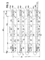
- FIGS. 5 a and 5 b show the correction of a fault using the pause period according to an example embodiment of the present invention.
- FIGS. 6 a and 6 b show a plurality of successive basic cycles with a correction according to an example embodiment of the present invention being determined.
- FIG. 1 shows a bus system 100 having a plurality of bus stations 101 to 105 .
- Each station 101 to 105 has its own time basis 106 to 110 which on the one hand may be formed by an internal element, for example a clock, a counter, a clock generator etc. or may be transmitted to the respective station from the outside.
- the respective local time basis LZ 1 to LZ 4 is, for example, especially a counter, for example a 16-bit incremental counter, that may be influenced only by a hard reset.
- a local time basis is implemented here in each station 102 to 105 .
- One specific station, the timer, in this case 101 has an exposed position.
- Its time basis 106 is referred to as the global time basis having the global time GZ and is either implemented in the timer 101 or transmitted thereto from the outside.
- All the other stations form their view of the global time GZ from their local time LZ (LZ 1 to LZ 4 ) and the local offset OS 1 to OS 4 (and in exceptional cases from OSG when OSG ⁇ 0, for example, when GZ is transmitted to timer 101 from the outside and the latter additionally contains its own time basis).
- the local offset is the difference between the local time at the instant of transmission (SOF, start of frame), of reference message RN and the global time information transmitted from the timer in or with that reference message RN.
- time marks ZM 1 to ZM 4 and ZMG may be used, which may be stored in registers and from which it is possible to determine time correction quantities, for example the offset relative to the global time, or also a correction value for error handling, especially the correction value according to the present invention.
- a time mark is a relative point in time which establishes the relationship between the relative time and an action in the original bus (CAN controller).
- a time mark is represented as a register, a controller being capable of managing a plurality of time marks.
- a plurality of time marks may be assigned to a message.
- Reference message RN is the basis for the time-triggered, periodic operation of TTCAN and arrow 112 indicates that reference message RN ( 111 ) is sent to the other stations ( 102 to 105 ). RN is clearly identified by a specific identifier and is received by all stations (in this case 102 to 105 ) as clocking information.
- FIG. 2 shows a system composed of a plurality of, and in this case two, TTCAN bus systems.
- 203 B 1 denotes therein a first bus, and 203 B 2 a second bus.
- Two stations 201 and 202 are coupled to the first bus 203 B 1 .
- One station 205 is coupled to the second bus 203 B 2 .
- Station 200 is connected to both buses 203 B 1 and 203 B 2 and acts as a connecting station or as a gateway computer, or as gateway station or gateway controller, which has access to both bus systems. Connection of the individual stations to the respective bus system is via an appropriate interface element, for example interface element 210 B 1 in the case of station 201 .
- Station 200 is similarly connected as a gateway station via an interface element 204 B 1 to bus 203 B 1 and via an interface element 204 B 2 to bus 203 B 2 .
- a clock generator 211 and 206 respectively, and a timer component having an internal clock source or also a local time basis 207 and 212 , respectively; especially a crystal or an oscillator, especially a VCO (voltage controlled oscillator).
- a time-recording component e.g., a counter 208 or 213 , respectively.
- Control functions in the respective station especially for the input/output of data on the bus system, for taking time information from the timer component, or also the calculation of the offset and the determination of the correction values for comparison of the time marks and for synchronizing the buses and bus stations, and further processes and process steps may be performed by components 209 and 214 forming processing components, especially a microcomputer or microprocessor or also a controller. Parts of those functionalities or the entire functionality may, however, be present directly, that is, implemented, in the respective interface component.
- the gateway station also may be specified as the timer of the global time, that is to say, as the sender of the reference message, especially for both bus systems. Essentially, therefore, the system composed of at least two bus systems shown in FIG.
- FIG. 3 shows the principle of exchanging data by time-triggered, periodic transmission of messages over time. That message transmission is clocked by the timer of the respective bus system using reference message RN.
- basic cycle BZ may, as shown here, include the actual time windows for messages ZF 1 to ZF 4 and also ZFRN, the time window for the reference message, and a pause period PZ.
- Cycle time ZZ generally corresponds to the time for such a basic cycle.
- time windows for data transmission ZF 1 to ZF 4 will be referred to hereinafter as data cycle DZ, cycle time ZZ including reference message RN in basic cycle BZ and also pause period PZ, in this case from t 0 to t 6 , t 6 to t 12 , t 12 to t 18 , and t 18 to t 24 .
- reference messages RN of the respective basic cycles BZ 0 to BZ 3 are transmitted.
- the structure of the time windows ZF 1 to ZF 4 that follow a reference message RN i.e., their length in segments S, their number and their position in time, may be specified. It is thereby possible to form from a plurality of basic cycles with their associated reference messages, data cycles and pause periods a total cycle GZ which begins at t 0 and ends at t 24 , in order to be repeated again.
- Time windows ZF 1 to ZF 4 include, for example, from two to five segments S each having, for example, 16, 32, 64, etc. bit times.
- the messages sent are shown circled in FIG. 3 as RN and A to F. All of those messages of all the stations of at least one bus system are organized as components of a matrix that represents the total cycle GZ, the so-called communication matrix. That communication matrix is composed, therefore, of the individual cycles BZ 0 to BZ 3 with their associated reference message RN, corresponding data cycle DZ 0 to DZ 3 and associated pause period PZ. Those data cycles DZ 0 to DZ 3 may optionally be made up of exclusive and arbitrating components.
- an entire time window such as ZF 3 here, may be specified as being arbitrating in accordance with CAN or, alternatively, only a single element of a basic cycle or data cycle, such as, for example, from t 15 to t 16 . It is possible here for the arrangement of the messages (A to F) within basic cycles BZ and data cycles DZ to be freely specified.
- a time window ZFx is linked for exclusive components to a CAN message object, it also being possible for a time window to be left empty or used for arbitrating components.
- a communication matrix in TTCAN is composed either of basic cycles with nothing but data cycles of equal length with reference message or it may add a pause, that is, a pause period PZ, in the data traffic after one or more data cycles, which pause period (PZ) is ended, for example, by an event, such as a new reference message.
- a pause period PZ is provided after every data cycle, i.e., in every basic cycle, in this case therefore from t 5 to t 6 , t 11 to t 12 , t 17 to t 18 and t 23 to t 24 .
- a pause period it is also possible, however, for such a pause period to be provided only after one data cycle or after every even number of data cycles, that is to say, 2 n where n is a natural number.
- a pause period PZ may also occur after every odd number of data cycles, that is to say, at 2 n +1, again with n as a natural number.
- the length of a basic cycle or the duration of the cycle time ZZ is made up of the time window for the reference message ZFRN, the data cycle DZ and, as shown here in FIG. 3 , the pause period PZ, that is to say, of a larger fixed part and a smaller pause. This method allows adaptation of the cycle time by adaptation of pause period PZ.
- a pause that is required after a data cycle may additionally be obtained by lengthening that cyclic pause period PZ.
- pause period PZ is included in the basic cycle.
- Basic cycle BZ may refer to ZFRN plus DZ and the pause period may be regarded as being added, which, however, merely corresponds to a different notation and is just as advantageous to the concept of the present invention and cannot result in any limitation.
- FIGS. 4 , 5 and 6 the example embodiment of the present invention will be described once more in detail.
- FIG. 4 a shows a normal procedure with reference message RN in basic cycle BZ without the use of the pause period PZ.
- reference message RN(n) begins.
- RN(n) has been completely transmitted and is valid.
- the next reference message RN(n+1) begins at time ts 1 , which is then valid at time tEN, and the next data cycle DZ follows. If, as shown in FIG. 4 b , a fault occurs, a re-start of that reference message RN(n) takes place at time tNS.
- a defective message identified by an error frame is repeated at that time tNS, since it is not possible to do without that reference message.
- That repeated reference message RN(n) is then valid at time tE 2 , whereupon data cycle DZ then follows in basic cycle BZ. That repetition of the message results, however, in the affected cycle time ZZ being extended and in the corresponding basic cycle BZ being shifted, in particular delayed. That is to say, at the actual start time of the next reference message RN(n+1), ts 1 , the basic cycle BZ has not yet ended and does not end until time ts 2 .
- the start of the subsequent reference message RN(n+1) does not occur until TS 2 , thereby producing a deviation, especially a delay, of ts 2 ⁇ ts 1 caused by the fault, that is to say, the associated cycle time and the end of the basic cycle affected is extended by that time.
- a deviation, especially a delay, of ts 2 ⁇ ts 1 caused by the fault that is to say, the associated cycle time and the end of the basic cycle affected is extended by that time.
- ts 2 ⁇ ts 1 caused by the fault
- cycle time ZZ will be composed of a constant time component, the very data cycle DZ and reference message RN, and of a variable component, a regular pause or pause period PZ.
- Cycle time ZZ is divided into the fixed time in the error-free case from ts to tp of, for example, 850 bit times and the pause time from tp to ts 3 of, for example, 50 bit times, once again producing in the example, as mentioned in the case of FIG. 4 , the 900 bit times. Accordingly, as shown in FIG.
- the total basic cycle BZ therefore includes according to the present invention reference message RN, data cycle DZ and pause period PZ, the cycle time then including a possible fault and a corresponding delay and hence being capable of being kept constant. This means that the basic cycle according to the present invention of the TTCAN lasts from the beginning of the reference message to the end of a possible pause period PZ.
- a start of the new reference message RN(n+1) either occurs after the end of pause period PZ at time ts 3 , which has then been transmitted and is valid at time tE 3 , or alternatively already occurs at the end of data cycle DZ if no pause period is provided in a basic cycle, so that compensation of a deviation occurs in the next basic cycle having a pause period.
- the time compensation may be distributed over several basic cycles and pause periods. That distribution may, on the one hand, be specified according to any desired specifiable scheme: 2 ⁇ 3 to the first pause period, 1 ⁇ 3 to the second pause period, or 1 ⁇ 4 to the first pause period, half to the second pause period, 1 ⁇ 4 to the third pause period, and so on, or distribution may preferably be performed by equal distribution, that is to say equal components corresponding to the number of pause periods within total cycle GZ. That distribution also makes it possible to keep that pause period small, since that time is not available for communication over the bus and thus reduces the possible bus utilization ratio. As shown in FIG. 3 , the possible shortening of the cycle time is taken into consideration in the communication matrix.
- a pause period also does not have to be provided in every basic cycle but may be provided, for example, at the end of every 2 n th basic cycle or at the end of every 2 n +1 th basic cycle, where n is a natural number (n ⁇ N), thereby allowing time compensation to be made only at every second (odd or even) cycle in the event of a fault.
- FIG. 6 a shows the course of three successive basic cycles, showing in this case fault-free operation. Shown here are the start times of the respective reference messages RN 1 to RN 4 , the times when the respective reference messages RN 1 to RN 3 are valid and the beginning of the respective pause period PZ 1 to PZ 3 .
- FIG. 6 a shows fault-free operation for the exchange of data.
- FIG. 6 b substantially corresponds to FIG. 6 a except that here a fault occurs and the correction of that error by determination of a correction value is shown.
- the cycle time is updated at each point in time when the reference message is valid, RNvalid.
- the difference between the basic cycle length and the cycle time read out in the previous basic cycle is calculated and is added to the currently read cycle time.
- the difference between the calculated local time difference and the calculated comparison value of the cycle time gives the delay due to message repetitions of the reference messages.
- the respective times in the cycle time are denoted by C and the respective times in the local time by L.
- That correction value is the quantity for one-off or distributed shortening of the regular pause period PZ.
Abstract
Description
tLn=Ln+1−Ln or, in this case, tL2=L3−L2.
tnComparison=(length of cycle time ZZ−Cn+Cn+1) or, in this case, by
t2Comparison=900 bit times−C2+C3.
Claims (10)
Applications Claiming Priority (4)
| Application Number | Priority Date | Filing Date | Title |
|---|---|---|---|
| DE10327548.7 | 2003-06-18 | ||
| DE10327548 | 2003-06-18 | ||
| DE10327548.7A DE10327548B4 (en) | 2003-06-18 | 2003-06-18 | Method and device for exchanging data via a bus system |
| PCT/EP2004/050466 WO2004111859A2 (en) | 2003-06-18 | 2004-04-07 | Method, device and system for the exchange of data via a bus system |
Publications (2)
| Publication Number | Publication Date |
|---|---|
| US20060174042A1 US20060174042A1 (en) | 2006-08-03 |
| US7761634B2 true US7761634B2 (en) | 2010-07-20 |
Family
ID=33520713
Family Applications (1)
| Application Number | Title | Priority Date | Filing Date |
|---|---|---|---|
| US10/560,959 Expired - Lifetime US7761634B2 (en) | 2003-06-18 | 2004-04-07 | Method, device and system for exchanging data via a bus system |
Country Status (5)
| Country | Link |
|---|---|
| US (1) | US7761634B2 (en) |
| EP (1) | EP1639758B1 (en) |
| JP (1) | JP4224100B2 (en) |
| DE (1) | DE10327548B4 (en) |
| WO (1) | WO2004111859A2 (en) |
Families Citing this family (14)
| Publication number | Priority date | Publication date | Assignee | Title |
|---|---|---|---|---|
| DE102004030969A1 (en) * | 2004-06-26 | 2006-01-12 | Robert Bosch Gmbh | Method and device for controlling a bus system and corresponding bus system |
| DE102004057410B4 (en) * | 2004-11-26 | 2015-11-12 | Robert Bosch Gmbh | Arrangement with an interface module and interface module |
| DE102008004854B4 (en) * | 2008-01-17 | 2015-06-18 | Audi Ag | Method for transmitting messages in a bus system, bus device and bus system |
| DE102009000584A1 (en) * | 2009-02-03 | 2010-08-05 | Robert Bosch Gmbh | Diagnosis of the synchronization of two communication networks of an electronic data processing system |
| JP4766160B2 (en) | 2009-07-29 | 2011-09-07 | 株式会社デンソー | Communication system and communication node |
| DE102010003530A1 (en) * | 2010-03-31 | 2011-10-06 | Robert Bosch Gmbh | Hardware data processing unit and method for monitoring a rounding duration of a routing unit |
| DE102010041368A1 (en) | 2010-09-24 | 2012-04-19 | Robert Bosch Gmbh | Method and subscriber station for the optimized transmission of data between subscriber stations of a bus system |
| DE102010041363A1 (en) * | 2010-09-24 | 2012-03-29 | Robert Bosch Gmbh | Apparatus and method for providing global time information in event-driven bus communication |
| AT512528B1 (en) * | 2012-05-15 | 2013-09-15 | Fts Computertechnik Gmbh | Method and apparatus for switching timed and event-driven messages |
| US9244753B2 (en) * | 2013-03-15 | 2016-01-26 | Siemens Schweiz Ag | Redundant bus fault detection |
| DK3099020T3 (en) * | 2015-10-21 | 2018-09-17 | Piller Group Gmbh | PROCEDURE FOR DATA COMMUNICATION BETWEEN A LIMITED NUMBER OF COMMUNICATION PARTNERS CONNECTED TO A COMMON COMMUNICATION NETWORK |
| DE102015223435A1 (en) | 2015-11-26 | 2017-06-01 | Robert Bosch Gmbh | Method and device for evaluating signal data |
| WO2019123458A1 (en) * | 2017-12-24 | 2019-06-27 | Technion Research & Development Foundation Limited | Message authentication based on a physical location on a bus |
| DE102018201302A1 (en) * | 2018-01-29 | 2019-08-01 | Robert Bosch Gmbh | Method for operating a radar sensor system in a motor vehicle |
Citations (20)
| Publication number | Priority date | Publication date | Assignee | Title |
|---|---|---|---|---|
| EP0522607A1 (en) | 1991-05-29 | 1993-01-13 | Telefonaktiebolaget L M Ericsson | A method and an arrangement for synchronizing two or more communication networks of the time multiplex type |
| EP0622712A2 (en) | 1993-04-28 | 1994-11-02 | Allen-Bradley Company | Communication network with time coordinated station activity |
| US5598579A (en) * | 1994-04-25 | 1997-01-28 | Compaq Computer Corporation | System fpr transferring data between two buses using control registers writable by host processor connected to system bus and local processor coupled to local bus |
| US5666358A (en) * | 1995-10-16 | 1997-09-09 | General Instrument Corporation Of Delaware | Method and apparatus for supporting TDMA operating over hybrid fiber coaxial (HFC) or other channels |
| US5694542A (en) * | 1995-11-24 | 1997-12-02 | Fault Tolerant Systems Fts-Computertechnik Ges.M.B. | Time-triggered communication control unit and communication method |
| US6111888A (en) | 1997-05-27 | 2000-08-29 | Micro Motion, Inc. | Deterministic serial bus communication system |
| US6128318A (en) * | 1998-01-23 | 2000-10-03 | Philips Electronics North America Corporation | Method for synchronizing a cycle master node to a cycle slave node using synchronization information from an external network or sub-network which is supplied to the cycle slave node |
| EP1115219A2 (en) | 2000-01-05 | 2001-07-11 | Robert Bosch Gmbh | Method and device for data exchange between at least two subscribers connected by a bus system |
| DE10000304A1 (en) | 2000-01-05 | 2001-07-12 | Bosch Gmbh Robert | Method and device for exchanging data between at least two participants connected to a bus system |
| DE10000302A1 (en) | 2000-01-05 | 2001-07-12 | Bosch Gmbh Robert | Data communication between two subscribers connected with bus system, involves stopping transmission of message from first subscriber to second subscriber at the end of first cycle |
| DE10000305A1 (en) | 2000-01-05 | 2001-07-12 | Bosch Gmbh Robert | Data transfer method involves transmitting message in time windows of given length |
| US20020067737A1 (en) | 2000-12-05 | 2002-06-06 | Arild Wego | Arrangement and method for transmitting data over a TDM bus |
| US6442708B1 (en) * | 1999-12-14 | 2002-08-27 | Honeywell International Inc. | Fault localization and health indication for a controller area network |
| US6516364B1 (en) | 1999-06-08 | 2003-02-04 | Endress+Hauser Gmbh+Co. | Method for time coordination of the transmission of data on a bus |
| US20030070019A1 (en) | 2001-09-26 | 2003-04-10 | Lambros Dalakuras | Method and device for transmitting information on a bus system, and a bus system |
| US6769038B1 (en) * | 1999-09-07 | 2004-07-27 | Bath Iron Works | Method and apparatus for a wearable computer |
| US6804205B1 (en) * | 1999-05-28 | 2004-10-12 | Sharp Kabushiki Kaisha | Method and apparatus for transmitting packet for synchronization using half duplex transmission medium |
| US20040228366A1 (en) * | 2002-04-15 | 2004-11-18 | Thomas Fuehrer | Bus system and method and device for transmitting communications on a bus system |
| US7184449B2 (en) * | 2000-10-10 | 2007-02-27 | Sony Deutschland Gmbh | Cycle synchronization between interconnected sub-networks |
| US7441048B2 (en) * | 2001-09-26 | 2008-10-21 | Siemens Aktiengesellschaft | Communications system and method for synchronizing a communications cycle |
Family Cites Families (2)
| Publication number | Priority date | Publication date | Assignee | Title |
|---|---|---|---|---|
| DE19721740B4 (en) * | 1997-05-24 | 2005-06-30 | Bosch Rexroth Ag | Control method for media access on a serial bus |
| DE60041470D1 (en) * | 1999-05-11 | 2009-03-19 | Canon Kk | Method and apparatus for synchronization between two networks |
-
2003
- 2003-06-18 DE DE10327548.7A patent/DE10327548B4/en not_active Expired - Lifetime
-
2004
- 2004-04-07 US US10/560,959 patent/US7761634B2/en not_active Expired - Lifetime
- 2004-04-07 JP JP2006516100A patent/JP4224100B2/en not_active Expired - Lifetime
- 2004-04-07 EP EP04741456.0A patent/EP1639758B1/en not_active Expired - Lifetime
- 2004-04-07 WO PCT/EP2004/050466 patent/WO2004111859A2/en active Application Filing
Patent Citations (23)
| Publication number | Priority date | Publication date | Assignee | Title |
|---|---|---|---|---|
| EP0522607A1 (en) | 1991-05-29 | 1993-01-13 | Telefonaktiebolaget L M Ericsson | A method and an arrangement for synchronizing two or more communication networks of the time multiplex type |
| JPH06169495A (en) | 1991-05-29 | 1994-06-14 | Telefon Ab L M Ericsson | Method and apparatus for synchronization of two or more time-multiplex communication networks |
| EP0622712A2 (en) | 1993-04-28 | 1994-11-02 | Allen-Bradley Company | Communication network with time coordinated station activity |
| US5598579A (en) * | 1994-04-25 | 1997-01-28 | Compaq Computer Corporation | System fpr transferring data between two buses using control registers writable by host processor connected to system bus and local processor coupled to local bus |
| US5666358A (en) * | 1995-10-16 | 1997-09-09 | General Instrument Corporation Of Delaware | Method and apparatus for supporting TDMA operating over hybrid fiber coaxial (HFC) or other channels |
| US5694542A (en) * | 1995-11-24 | 1997-12-02 | Fault Tolerant Systems Fts-Computertechnik Ges.M.B. | Time-triggered communication control unit and communication method |
| US6111888A (en) | 1997-05-27 | 2000-08-29 | Micro Motion, Inc. | Deterministic serial bus communication system |
| US6128318A (en) * | 1998-01-23 | 2000-10-03 | Philips Electronics North America Corporation | Method for synchronizing a cycle master node to a cycle slave node using synchronization information from an external network or sub-network which is supplied to the cycle slave node |
| US6804205B1 (en) * | 1999-05-28 | 2004-10-12 | Sharp Kabushiki Kaisha | Method and apparatus for transmitting packet for synchronization using half duplex transmission medium |
| US6516364B1 (en) | 1999-06-08 | 2003-02-04 | Endress+Hauser Gmbh+Co. | Method for time coordination of the transmission of data on a bus |
| US6769038B1 (en) * | 1999-09-07 | 2004-07-27 | Bath Iron Works | Method and apparatus for a wearable computer |
| US6442708B1 (en) * | 1999-12-14 | 2002-08-27 | Honeywell International Inc. | Fault localization and health indication for a controller area network |
| DE10000303A1 (en) | 2000-01-05 | 2001-07-12 | Bosch Gmbh Robert | Data communication method for bus system subscribers has time information provided by one subscriber used for correcting local clock source at each other subscriber |
| JP2001251329A (en) | 2000-01-05 | 2001-09-14 | Robert Bosch Gmbh | Data exchange method and its system |
| DE10000305A1 (en) | 2000-01-05 | 2001-07-12 | Bosch Gmbh Robert | Data transfer method involves transmitting message in time windows of given length |
| DE10000302A1 (en) | 2000-01-05 | 2001-07-12 | Bosch Gmbh Robert | Data communication between two subscribers connected with bus system, involves stopping transmission of message from first subscriber to second subscriber at the end of first cycle |
| DE10000304A1 (en) | 2000-01-05 | 2001-07-12 | Bosch Gmbh Robert | Method and device for exchanging data between at least two participants connected to a bus system |
| EP1115219A2 (en) | 2000-01-05 | 2001-07-11 | Robert Bosch Gmbh | Method and device for data exchange between at least two subscribers connected by a bus system |
| US7184449B2 (en) * | 2000-10-10 | 2007-02-27 | Sony Deutschland Gmbh | Cycle synchronization between interconnected sub-networks |
| US20020067737A1 (en) | 2000-12-05 | 2002-06-06 | Arild Wego | Arrangement and method for transmitting data over a TDM bus |
| US20030070019A1 (en) | 2001-09-26 | 2003-04-10 | Lambros Dalakuras | Method and device for transmitting information on a bus system, and a bus system |
| US7441048B2 (en) * | 2001-09-26 | 2008-10-21 | Siemens Aktiengesellschaft | Communications system and method for synchronizing a communications cycle |
| US20040228366A1 (en) * | 2002-04-15 | 2004-11-18 | Thomas Fuehrer | Bus system and method and device for transmitting communications on a bus system |
Non-Patent Citations (8)
| Title |
|---|
| An Introduction to TTCAN, Rahul Shah, Xuanming Dong, Mar. 7, 2002. * |
| FlexRay International Workshop, Claas Bracklo, Mar. 4, 2003. * |
| Florian Hartwiich, et al, Timing in the TTCAN Network, Robert Bosch GmbH Proceedings 8th International CAN Conference. |
| G. Leen et al , TTCAN: a new time-triggered controller area network, Dec. 14, 2001, Microprocessors and Microsystems 26, (2002) 77-94). * |
| ISO 118-4:2004-Aug. 5, 2005. |
| Leen, G., et al., "TTCAN: A new time-triggered controller area network", Microprocessors and Microsystems, IPC Business Press Ltd., London, Great Britain, vol. 26, No. 2, Mar. 17, 2002, pp. 77-94. |
| Rahul Shah & Xuanming Dong, An Introduction to TTCAN, EE2900 Class discussion, Mar. 7, 2002, pp. 9-34. * |
| Scheduling for a TTCAN network with Stochastic Optimization Algorithm, Jose Fonseca, Fernanda Coutinho, Jorge Barreiros, Portugal. * |
Also Published As
| Publication number | Publication date |
|---|---|
| WO2004111859A2 (en) | 2004-12-23 |
| WO2004111859A3 (en) | 2005-02-10 |
| DE10327548A1 (en) | 2005-01-13 |
| EP1639758B1 (en) | 2013-06-19 |
| DE10327548B4 (en) | 2014-05-22 |
| JP4224100B2 (en) | 2009-02-12 |
| US20060174042A1 (en) | 2006-08-03 |
| JP2006527938A (en) | 2006-12-07 |
| EP1639758A2 (en) | 2006-03-29 |
Similar Documents
| Publication | Publication Date | Title |
|---|---|---|
| JP4824666B2 (en) | Method and apparatus for synchronizing global time of a plurality of buses, and bus system corresponding to such a method and apparatus | |
| US8321612B2 (en) | Method and device for synchronizing two bus systems by transmission of a time associated trigger signal from one system to another | |
| US7761634B2 (en) | Method, device and system for exchanging data via a bus system | |
| JP4813665B2 (en) | Data exchange method and apparatus | |
| AU2002302300B2 (en) | Synchronization of at least one node of a bus system | |
| JP2003521144A (en) | Method and apparatus for exchanging data between at least two subscribers coupled to a bus system | |
| US9319237B2 (en) | Method and device for controlling a bus system and a corresponding bus system | |
| JP2007060400A (en) | Method and system for controlling communication timing | |
| CN111030909B (en) | Method for time synchronization among CAN bus multi-master device communication | |
| JP2001223720A (en) | Method and device for exchanging data | |
| Akpinar et al. | Improved clock synchronization algorithms for the controller area network (CAN) | |
| AU2002340733B2 (en) | Method and device for producing program interruptions in subscribers to a bus system, and corresponding bus system | |
| Fuehrer et al. | Time triggered can (ttcan) | |
| JP4394351B2 (en) | Method for generating clock pulses in a bus system having at least one subscriber, apparatus, bus system and subscriber | |
| JP4927906B2 (en) | Method for generating clock pulses in a bus system having at least one subscriber, apparatus, bus system and subscriber | |
| CN114375552B (en) | Method for time synchronization in Ethernet-based network | |
| Kammerer | TTCAN | |
| Kammerer et al. | Time-Triggered CAN |
Legal Events
| Date | Code | Title | Description |
|---|---|---|---|
| AS | Assignment |
Owner name: ROBERT BOSCH GMBH, GERMANY Free format text: ASSIGNMENT OF ASSIGNORS INTEREST;ASSIGNORS:WEIGL, ANDREAS;HUGEL, ROBERT;SIGNING DATES FROM 20051129 TO 20051205;REEL/FRAME:017345/0123 Owner name: ROBERT BOSCH GMBH, GERMANY Free format text: ASSIGNMENT OF ASSIGNORS INTEREST;ASSIGNORS:WEIGL, ANDREAS;HUGEL, ROBERT;REEL/FRAME:017345/0123;SIGNING DATES FROM 20051129 TO 20051205 |
|
| STCF | Information on status: patent grant |
Free format text: PATENTED CASE |
|
| FPAY | Fee payment |
Year of fee payment: 4 |
|
| MAFP | Maintenance fee payment |
Free format text: PAYMENT OF MAINTENANCE FEE, 8TH YEAR, LARGE ENTITY (ORIGINAL EVENT CODE: M1552) Year of fee payment: 8 |
|
| MAFP | Maintenance fee payment |
Free format text: PAYMENT OF MAINTENANCE FEE, 12TH YEAR, LARGE ENTITY (ORIGINAL EVENT CODE: M1553); ENTITY STATUS OF PATENT OWNER: LARGE ENTITY Year of fee payment: 12 |