US775565A - Buttonhole-cutter for sewing-machines. - Google Patents
Buttonhole-cutter for sewing-machines. Download PDFInfo
- Publication number
- US775565A US775565A US1902093674A US775565A US 775565 A US775565 A US 775565A US 1902093674 A US1902093674 A US 1902093674A US 775565 A US775565 A US 775565A
- Authority
- US
- United States
- Prior art keywords
- buttonhole
- knife
- sewing
- ejector
- cutter
- Prior art date
- Legal status (The legal status is an assumption and is not a legal conclusion. Google has not performed a legal analysis and makes no representation as to the accuracy of the status listed.)
- Expired - Lifetime
Links
- 238000009958 sewing Methods 0.000 description 8
- 239000000463 material Substances 0.000 description 6
- 238000010276 construction Methods 0.000 description 2
- 239000004744 fabric Substances 0.000 description 2
- 239000002184 metal Substances 0.000 description 1
- 239000002759 woven fabric Substances 0.000 description 1
Images
Classifications
-
- B—PERFORMING OPERATIONS; TRANSPORTING
- B26—HAND CUTTING TOOLS; CUTTING; SEVERING
- B26D—CUTTING; DETAILS COMMON TO MACHINES FOR PERFORATING, PUNCHING, CUTTING-OUT, STAMPING-OUT OR SEVERING
- B26D7/00—Details of apparatus for cutting, cutting-out, stamping-out, punching, perforating, or severing by means other than cutting
- B26D7/18—Means for removing cut-out material or waste
- B26D7/1818—Means for removing cut-out material or waste by pushing out
-
- Y—GENERAL TAGGING OF NEW TECHNOLOGICAL DEVELOPMENTS; GENERAL TAGGING OF CROSS-SECTIONAL TECHNOLOGIES SPANNING OVER SEVERAL SECTIONS OF THE IPC; TECHNICAL SUBJECTS COVERED BY FORMER USPC CROSS-REFERENCE ART COLLECTIONS [XRACs] AND DIGESTS
- Y10—TECHNICAL SUBJECTS COVERED BY FORMER USPC
- Y10S—TECHNICAL SUBJECTS COVERED BY FORMER USPC CROSS-REFERENCE ART COLLECTIONS [XRACs] AND DIGESTS
- Y10S83/00—Cutting
- Y10S83/905—Buttonhole making
-
- Y—GENERAL TAGGING OF NEW TECHNOLOGICAL DEVELOPMENTS; GENERAL TAGGING OF CROSS-SECTIONAL TECHNOLOGIES SPANNING OVER SEVERAL SECTIONS OF THE IPC; TECHNICAL SUBJECTS COVERED BY FORMER USPC CROSS-REFERENCE ART COLLECTIONS [XRACs] AND DIGESTS
- Y10—TECHNICAL SUBJECTS COVERED BY FORMER USPC
- Y10T—TECHNICAL SUBJECTS COVERED BY FORMER US CLASSIFICATION
- Y10T83/00—Cutting
- Y10T83/202—With product handling means
- Y10T83/2092—Means to move, guide, or permit free fall or flight of product
- Y10T83/2096—Means to move product out of contact with tool
- Y10T83/2122—By ejector within a hollow cutter
- Y10T83/2127—Ejector operated with return stroke of cutter
-
- Y—GENERAL TAGGING OF NEW TECHNOLOGICAL DEVELOPMENTS; GENERAL TAGGING OF CROSS-SECTIONAL TECHNOLOGIES SPANNING OVER SEVERAL SECTIONS OF THE IPC; TECHNICAL SUBJECTS COVERED BY FORMER USPC CROSS-REFERENCE ART COLLECTIONS [XRACs] AND DIGESTS
- Y10—TECHNICAL SUBJECTS COVERED BY FORMER USPC
- Y10T—TECHNICAL SUBJECTS COVERED BY FORMER US CLASSIFICATION
- Y10T83/00—Cutting
- Y10T83/202—With product handling means
- Y10T83/2092—Means to move, guide, or permit free fall or flight of product
- Y10T83/2096—Means to move product out of contact with tool
- Y10T83/2122—By ejector within a hollow cutter
- Y10T83/2129—By means carried by cooperating cutter
-
- Y—GENERAL TAGGING OF NEW TECHNOLOGICAL DEVELOPMENTS; GENERAL TAGGING OF CROSS-SECTIONAL TECHNOLOGIES SPANNING OVER SEVERAL SECTIONS OF THE IPC; TECHNICAL SUBJECTS COVERED BY FORMER USPC CROSS-REFERENCE ART COLLECTIONS [XRACs] AND DIGESTS
- Y10—TECHNICAL SUBJECTS COVERED BY FORMER USPC
- Y10T—TECHNICAL SUBJECTS COVERED BY FORMER US CLASSIFICATION
- Y10T83/00—Cutting
- Y10T83/869—Means to drive or to guide tool
- Y10T83/8798—With simple oscillating motion only
-
- Y—GENERAL TAGGING OF NEW TECHNOLOGICAL DEVELOPMENTS; GENERAL TAGGING OF CROSS-SECTIONAL TECHNOLOGIES SPANNING OVER SEVERAL SECTIONS OF THE IPC; TECHNICAL SUBJECTS COVERED BY FORMER USPC CROSS-REFERENCE ART COLLECTIONS [XRACs] AND DIGESTS
- Y10—TECHNICAL SUBJECTS COVERED BY FORMER USPC
- Y10T—TECHNICAL SUBJECTS COVERED BY FORMER US CLASSIFICATION
- Y10T83/00—Cutting
- Y10T83/929—Tool or tool with support
- Y10T83/9411—Cutting couple type
- Y10T83/9423—Punching tool
- Y10T83/9437—Shear-type female tool
-
- Y—GENERAL TAGGING OF NEW TECHNOLOGICAL DEVELOPMENTS; GENERAL TAGGING OF CROSS-SECTIONAL TECHNOLOGIES SPANNING OVER SEVERAL SECTIONS OF THE IPC; TECHNICAL SUBJECTS COVERED BY FORMER USPC CROSS-REFERENCE ART COLLECTIONS [XRACs] AND DIGESTS
- Y10—TECHNICAL SUBJECTS COVERED BY FORMER USPC
- Y10T—TECHNICAL SUBJECTS COVERED BY FORMER US CLASSIFICATION
- Y10T83/00—Cutting
- Y10T83/929—Tool or tool with support
- Y10T83/9457—Joint or connection
Definitions
- Wi TNEEEES INVENTUR a fi I aY g 'ij m WW1.
- v ATTDRNEYE
- BUTTONHOLE CUTTER FOB SEWING MACHINES. Arrn l'oyuox FILED r2112, 190:.
- the buttonhole is cut in the form of a slit by a straight knife, a loop-shaped en largement being in some cases formed at one end or at both ends of the slit.
- a loop-shaped en largement being in some cases formed at one end or at both ends of the slit.
- the present invention has for its object to obviate the above-mentioned disadvantages; and it consists in cutting the buttonhole by means of a hollow knife in such manner that an actual oblong opening is formed inthe material along the entire length of the buttonhole, the edges of which are therefore no longer in contact with each other.
- a hollow knife By this means the drawing apart of the material on both sides of the buttonhole is entirely dispensed with. and the buttonholes when finished have a freer and straighter shape than those made as heretofore.
- special means must be provided for effectually removing the pieces of material cut out by the knife.
- the knife is made in the form of an oblong tubular punch, the interior of which widens out slightly from the cutting edge upward and which has at one end of its upper part a lateral projection by means of which it is secured by a screw to the vertically-reciprocating arm of usual construction.
- a small upright piece of metal or ejector For removing the pieces of material from the interior of the knife there is provided under the needle-plate a small upright piece of metal or ejector.
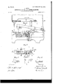
- Figures 1, 2, and 3 are three views of the knife, seen from above,from the side, and from below, respectively.
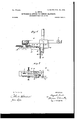
- Fig. 4 is an elevation, partly in section, of that portion of the sewing-machine which comprises the new knife and the parts cooperating therewith.
- Fig. 5 is a top view of the parts shown in Fig. 4.
- Fig. 6 is a section through Fig. 5 on the line C D.
- Fig. 7 is a section on line A B of Fig. 4.
- Figs. 1 and 3 show the knife as composed of two halves 1 and 2, carrying the edge 3 and lugs 4, by which the knife, which may be made in one piece, is attached to a lever 6 by screw 5 in a well-known way.
- the ejector 8 is a small plate fixed to an arm 9, whichwis fulcrumed at 10 and sprung upward by a spring 15, fixed to the pin 16 of the machine-frame at one end and to the pin 14 at the rear end 13 of the arm 9 at its other end.
- This rear end 13 is raised and the ejector 8 lowered by a finger 12 of the arm 11, which is fixed to the lever 6.
- This lever 6 is oscillated on its fulcrum 7 and the machinearm 28 carried forward and backward, as well known in the type of buttonhole-sewing machines shown in drawings hereto attached.
- a horizontal toothed sector 20 is oscillated in a well-known way. This sector carries a finger 22, which is by the movement of the sector brought to bear against a spring 17.
- This spring is provided with a pin 18, which protrudes into a cavity 19 of the arm 9 when the ejector 8 reaches its deepest position.
- a buttonhole-sewing machine the combination with a hollow knife, an ejector adapted to enter said knife, and means for locking the ejector in an inoperative position, of mechanism for projecting the ejector into the knife, means connected with the knife and arranged to bring the ejector back to its locked position upon the return of the knife, and mechanism for releasing the eject-orfrom the locking mechanism after the operative movement of the knife.
- a buttonhole-sewing machine the combination with two members, viz: a hollow knife and an ejector adapted to enter the same, of means for projecting one of said members toward the other, mechanism for temporarily locking said member in an inoperative position, means for imparting an operative movement tothe other member, mechanism connected with the last-named member and arranged tobring the first-named member back to its locked position, and mechanism for releasing said first-named'member from the locking mechanism after the operative movement of the other member.
- a support for the goods and a buttonhole-cutter movable toward and from said support, the operative portion or face of said cutter being sufficiently wide from end to end to remove a portion of the fabric from one endof the cut to the other, instead of simply slitting the fabric.
Landscapes
- Life Sciences & Earth Sciences (AREA)
- Forests & Forestry (AREA)
- Engineering & Computer Science (AREA)
- Mechanical Engineering (AREA)
- Sewing Machines And Sewing (AREA)
Description
No. 775,565; PATENTED NOV. 22, 1904. A.JBUDE. BUTTONHOLE CUTTER FOR SEWING MACHINES.
APPLICATION FILED PEB.12, 1902.
N0 MODEL. ZSHEETS-SHEET 1.
Wi TNEEEES: INVENTUR a fi I aY g 'ij m WW1. v ATTDRNEYE:
"No. 775,555. PATE TBI; NOV. 22, 1904.
' A.JEUDE.
BUTTONHOLE CUTTER FOB. SEWING MACHINES. Arrn l'oyuox FILED r2112, 190:.
no MODEL. 2 sums-sum 2.
WITNESEES: INVENTDR d nQ'm BY 26, 5 C 4 6% ATTIJRNEYS PATENT Patented November 22, 1904.
FFICE.
AUGUST JEUDE, OF OKRIFTEL, GERMANY, .ASSIGNOR TO AARON VAIL ROWLEY, OF FRANKFORT-ON-THE-MAIN, GERMANY.
BUTTONHOLE-CUTTER FOR SEWING-MACHINES.
SPECIFICATION forming part of Letters Patent No. 775,565, dated November 22, 1904.
Application filed February 12. 1902. Serial No. 93,674. (No model.) i
To a whom, it may concern:
Be it known that I, AUGUST J EUDE, mechanician, residing at Okriftel, near Hattersheim on-the-Main, German Empire, have invented new and useful Improvements in Buttonhole- Cutters for Sewing-Machines, of which the following is a specification. V p
In huttonhole-sewing machines of present construction the buttonhole is cut in the form of a slit by a straight knife, a loop-shaped en largement being in some cases formed at one end or at both ends of the slit. In all cases it was necessary after forming the slit and before effecting the buttonhole-stitching thereon to seize the material on each side thereof and draw it apart, so as to cause the slit to gape. This was liable to several disadvantages. On the one hand by such drawing apart the material was distorted and the edges were bulged. and on the other hand when the buttonholes were formed in woven fabrics there was danger of the longitudinal threads on the one side of the buttonhole-slit being seized by the stitching on the other side.
The present invention has for its object to obviate the above-mentioned disadvantages; and it consists in cutting the buttonhole by means of a hollow knife in such manner that an actual oblong opening is formed inthe material along the entire length of the buttonhole, the edges of which are therefore no longer in contact with each other. By this means the drawing apart of the material on both sides of the buttonhole is entirely dispensed with. and the buttonholes when finished have a freer and straighter shape than those made as heretofore. In employing such hollow knives according to the present invention special means must be provided for effectually removing the pieces of material cut out by the knife.
For the purposes of this invention the knife is made in the form of an oblong tubular punch, the interior of which widens out slightly from the cutting edge upward and which has at one end of its upper part a lateral projection by means of which it is secured by a screw to the vertically-reciprocating arm of usual construction.
For removing the pieces of material from the interior of the knife there is provided under the needle-plate a small upright piece of metal or ejector.
In order to enable anybody skilled in the art to carry out my invention, I have hereunto annexed drawings showing my invention as applied to a so-called Reece buttonhole-sewing machine.
Figures 1, 2, and 3 are three views of the knife, seen from above,from the side, and from below, respectively. Fig. 4 is an elevation, partly in section, of that portion of the sewing-machine which comprises the new knife and the parts cooperating therewith. Fig. 5 is a top view of the parts shown in Fig. 4. Fig. 6 is a section through Fig. 5 on the line C D. Fig. 7 is a section on line A B of Fig. 4. Figs. 1 and 3 show the knife as composed of two halves 1 and 2, carrying the edge 3 and lugs 4, by which the knife, which may be made in one piece, is attached to a lever 6 by screw 5 in a well-known way.
The ejector 8 is a small plate fixed to an arm 9, whichwis fulcrumed at 10 and sprung upward by a spring 15, fixed to the pin 16 of the machine-frame at one end and to the pin 14 at the rear end 13 of the arm 9 at its other end. This rear end 13 is raised and the ejector 8 lowered by a finger 12 of the arm 11, which is fixed to the lever 6. This lever 6 is oscillated on its fulcrum 7 and the machinearm 28 carried forward and backward, as well known in the type of buttonhole-sewing machines shown in drawings hereto attached. Also a horizontal toothed sector 20 is oscillated in a well-known way. This sector carries a finger 22, which is by the movement of the sector brought to bear against a spring 17. This spring is provided with a pin 18, which protrudes into a cavity 19 of the arm 9 when the ejector 8 reaches its deepest position. By moving the spring 17 sideward the finger 22 liberates the arm 9, and thus pushes the ejector 8 into the cavity of the knife 1 2 after the lattemporarily keeping the ejector stationary,
and means operated by the machine for releasing the ejector from said locking device.
2. In a buttonhole-sewing machine, the combination with a hollow knife, an ejector adapted to enter said knife, and means for locking the ejector in an inoperative position, of mechanism for projecting the ejector into the knife, means connected with the knife and arranged to bring the ejector back to its locked position upon the return of the knife, and mechanism for releasing the eject-orfrom the locking mechanism after the operative movement of the knife.
3. Inabuttonhole-sewing machine the combination of a hollow knife with a spring-driven ejector fixed to an oscillating arm with a spring attached to the said arm, a finger fixed to the lever carrying the knife and adapted to lower the ejector and a spring adapted to lock the ejector in its lowest position and a finger adapted to release the said spring, sub stantially as described.
' 4:. In a buttonhole-sewing machine,the combination with two members, viz: a hollow knife and an ejector adapted to enter the same, of means for projecting one of said members toward the other, mechanism for temporarily locking said member in an inoperative position, means for imparting an operative movement tothe other member, mechanism connected with the last-named member and arranged tobring the first-named member back to its locked position, and mechanism for releasing said first-named'member from the locking mechanism after the operative movement of the other member.
5. In a buttonhole-sewing machine, a support for the goods, anda buttonhole-cutter movable toward and from said support, the operative portion or face of said cutter being sufficiently wide from end to end to remove a portion of the fabric from one endof the cut to the other, instead of simply slitting the fabric.
In testimony whereof I have signed my name to this specification in the presence of two subscribing witnesses.
AUGUST EUDE.
Witnesses:
JEAN GRUND, CARL GRUND.
Priority Applications (1)
| Application Number | Priority Date | Filing Date | Title |
|---|---|---|---|
| US1902093674 US775565A (en) | 1902-02-12 | 1902-02-12 | Buttonhole-cutter for sewing-machines. |
Applications Claiming Priority (1)
| Application Number | Priority Date | Filing Date | Title |
|---|---|---|---|
| US1902093674 US775565A (en) | 1902-02-12 | 1902-02-12 | Buttonhole-cutter for sewing-machines. |
Publications (1)
| Publication Number | Publication Date |
|---|---|
| US775565A true US775565A (en) | 1904-11-22 |
Family
ID=2844050
Family Applications (1)
| Application Number | Title | Priority Date | Filing Date |
|---|---|---|---|
| US1902093674 Expired - Lifetime US775565A (en) | 1902-02-12 | 1902-02-12 | Buttonhole-cutter for sewing-machines. |
Country Status (1)
| Country | Link |
|---|---|
| US (1) | US775565A (en) |
-
1902
- 1902-02-12 US US1902093674 patent/US775565A/en not_active Expired - Lifetime
Similar Documents
| Publication | Publication Date | Title |
|---|---|---|
| US775565A (en) | Buttonhole-cutter for sewing-machines. | |
| US947506A (en) | Combination pressure-foot and trimming attachment for sewing-machines. | |
| US480031A (en) | Button-setting machine | |
| US1539629A (en) | Work-spacing mechanism for buttonhole-sewing machines | |
| US1015011A (en) | Buttonhole-machine. | |
| US1727807A (en) | Cutter knife for hemstitching machines | |
| US127145A (en) | Improvement in sewing-machines | |
| US896949A (en) | Attachment for sewing-machines for blindstitching, serging, overseaming, and the like. | |
| US1535025A (en) | Automatic picot-cutting attachment | |
| US1286452A (en) | Combined trimming mechanism and presser-foot. | |
| US580880A (en) | Shoe-sewing machine | |
| US1613540A (en) | Picot-cutting attachment | |
| US1232541A (en) | Paper-fastener. | |
| US1373747A (en) | Thread-cutting and thread-end-holding device for embroidery sewing-machines | |
| US1372630A (en) | Assiqnob to the | |
| US724282A (en) | Thread-cutter for sewing-machines. | |
| US1141041A (en) | Thread severing and holding mechanism for sewing-machines. | |
| US989668A (en) | Buttonhole cutting and stitching attachment for sewing-machines. | |
| US990610A (en) | Buttonhole cutting and stitching attachment for sewing-machines. | |
| US401399A (en) | Thread-cutting mechanism for sewing-machines | |
| US1118711A (en) | Presser-foot for sewing-machines. | |
| US269049A (en) | Machine guide | |
| US1139261A (en) | Thread-guard for sewing-machines. | |
| US954025A (en) | Cloth-cutting machine. | |
| US1374326A (en) | And mobbis g |