US7753063B1 - Attachable/detachable sun shade apparatus - Google Patents
Attachable/detachable sun shade apparatus Download PDFInfo
- Publication number
- US7753063B1 US7753063B1 US12/336,599 US33659908A US7753063B1 US 7753063 B1 US7753063 B1 US 7753063B1 US 33659908 A US33659908 A US 33659908A US 7753063 B1 US7753063 B1 US 7753063B1
- Authority
- US
- United States
- Prior art keywords
- elongated
- support
- press fit
- members
- chair
- Prior art date
- Legal status (The legal status is an assumption and is not a legal conclusion. Google has not performed a legal analysis and makes no representation as to the accuracy of the status listed.)
- Expired - Fee Related
Links
Images


Classifications
-
- A—HUMAN NECESSITIES
- A47—FURNITURE; DOMESTIC ARTICLES OR APPLIANCES; COFFEE MILLS; SPICE MILLS; SUCTION CLEANERS IN GENERAL
- A47C—CHAIRS; SOFAS; BEDS
- A47C7/00—Parts, details, or accessories of chairs or stools
- A47C7/62—Accessories for chairs
- A47C7/66—Means to protect against weather
Definitions
- the present invention relates generally to portable sun shades, and more particularly to those that are attachable to portable chairs.
- the sun shade invention includes a set of chair connectors that are “press fit” onto a frame member of a portable chair, and the chair connectors mechanically support the weight of the sun shade so that it maintains its position on the chair, without any other fasteners or locking hardware.
- the sun shade also includes a flexible support member, or a variable-angle spring, along each side of its overall frame structure, which allows the sun shade to be positioned at various angles with respect to the horizontal plane.
- the sun shade further includes an adjustable width capability so that it can be mounted onto different models of portable chairs, of different widths.
- support frame apparatus for a sun shade which comprises: (a) a first frame-half sub-assembly, comprising: a first elongated support member extending between a first end and a second end along a first longitudinal axis; a first elongated press fit chair connector member extending between a third end and a fourth end along a second longitudinal axis; a first variable angle member that is in mechanical communication with the second end of the first elongated support member and that is in mechanical communication with the third end of the first elongated press fit chair connector member; (b) a second frame-half sub-assembly, comprising: a second elongated support member extending between a fifth end and a sixth end along a third longitudinal axis; a second elongated press fit chair connector member extending between a seventh end and an eighth end along a fourth longitudinal axis; a second variable angle member that
- support frame apparatus for a sun shade comprises: (a) a first frame-half sub-assembly, comprising: a first elongated support member extending between a first end and a second end along a first longitudinal axis; a first elongated press fit chair connector member extending between a third end and a fourth end along a second longitudinal axis; a first variable angle member that is in mechanical communication with the second end of the first elongated support member and that is in mechanical communication with the third end of the first elongated press fit chair connector member; (b) a second frame-half sub-assembly, comprising: a second elongated support member extending between a fifth end and a sixth end along a third longitudinal axis; a second elongated press fit chair connector member extending between a seventh end and an eighth end along a fourth longitudinal axis; a second variable angle member that is in mechanical communication with the sixth end of the second
- FIG. 1 is a perspective view from the front and right side of a sun shade as it would be mounted to a portable canvas chair, and as constructed according to the principles of the present invention.
- FIG. 2 is an exploded view of the major parts of the framework sub-assembly for the sun shade of FIG. 1 .
- FIG. 3 is an elevational view of the framework sub-assembly of the sun shade of FIG. 1 , in which the flexible support members are not bent at an angle, but instead are disposed in a substantially linear manner.
- FIG. 4 is a perspective view in partial elevation of the framework sub-assembly of FIG. 3 .
- FIG. 5 is a plan view showing the pattern of the flexible material portions that are used in the sun shade of FIG. 1 .
- FIGS. 6A-6C are three views of an adapter that is used in the sun shade of FIG. 1 .
- FIGS. 7A-7C are three views of a coupler used in the sun shade of FIG. 1 .
- FIGS. 8A-8C are three views of an end cap that is used in the sun shade of FIG. 1 .
- FIGS. 9A-9D are four views of a flexible support member that is used in the sun shade of FIG. 1 .
- FIGS. 10A-10C are three views of a first embodiment chair connector that is used in the sun shade of FIG. 1 .
- FIGS. 11A-11C are three views of an alternative embodiment chair connector that is used in the sun shade of FIG. 1 .
- FIGS. 12A-12C are three views of a stretcher support arm that is used in the sun shade of FIG. 1 .
- FIGS. 13A-13C are three views of a first longitudinal support member that is used in the sun shade of FIG. 1 .
- FIGS. 14A-14C are three views of a second longitudinal support member that is used in the sun shade of FIG. 1 .
- FIGS. 15A-15C are three views of a pivotable locking member that is used in the sun shade of FIG. 1 .
- FIG. 16 is an elevational view from the side showing one-half of the framework sub-assembly used in the sun shade of FIG. 1 , in which the first and second support members are at an angular configuration of about 90°, by bending the flexible support member.
- FIG. 17 is an elevational view from the side showing one-half of the framework sub-assembly in which the first and second support members are at an angular configuration that is not 90°, by not bending the flexible support member.
- FIG. 18 is an elevational view from the side showing the entire sun shade of FIG. 1 , including the flexible material covering.
- FIG. 19 is a side view of a first alternative embodiment of a first portion of the framework sub-assembly for the sun shade of FIG. 1 .
- FIG. 20 is a side view of the first alternative embodiment of a second portion of the framework sub-assembly for the sun shade of FIG. 1 .
- FIG. 21 is a side view of a second alternative embodiment of one-half of the framework sub-assembly for the sun shade of FIG. 1 , in which the entire half portion of the framework is made from a single part.
- FIG. 22 is an elevational view showing an upper portion of the framework sub-assembly of the sun shade of FIG. 1 , in which the stretcher support arms are at their co-linear position that tends to stretch the flexible material covering.
- FIG. 23 is an elevational view of the same upper portion as depicted in FIG. 22 , in which the stretcher support arms are not in a co-linear position, and would not tend to stretch the flexible material covering.
- FIG. 24 is a perspective view from the left and rear side of a sun shade of a third alternative embodiment, and as constructed according to the principles of the present invention.
- FIG. 25 is another perspective view of the sun shade of FIG. 24 , however, the top panel of the flexible material has been removed so that some of the internal components can be seen.
- FIG. 26 is an elevational view of the framework sub-assembly of the sun shade of FIG. 24 , in which the flexible support members are not bent at an angle, but instead are disposed in a substantially linear manner.
- FIG. 27 is an exploded view of the major parts of the framework sub-assembly of FIG. 26 .
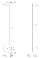
- FIGS. 28A-28C are three views of a second alternative embodiment chair connector that is used in the sun shade of FIG. 24 .
- FIG. 29 is a plan view of an alternative embodiment stretcher support arm that is used in the sun shade of FIG. 24 .
- FIG. 30 is a plan view of an alternative embodiment pivotable locking member that is used in the sun shade of FIG. 24 .
- FIGS. 31A and 31B are two views of a torsion spring that is used in the sun shade of FIG. 24 .
- FIG. 32 is an elevational view of a compacted configuration of the sun shade of FIG. 24 .
- first and second preceding an element name, e.g., first support member, second support member, etc., are used for identification purposes to distinguish between similar or related elements, results or concepts, and are not intended to necessarily imply order, nor are the terms “first” and “second” intended to preclude the inclusion of additional similar or related elements, results or concepts, unless otherwise indicated.
- the present invention is a sun shade, generally designated by the reference numeral 10 , that attaches to a folding canvas chair, which is generally designated by the reference numeral 80 . It will be understood that such portable canvas chairs are known in the prior art.
- the chair itself includes a top back frame member 82 , a pair of upright rear frame members 84 on either side of the top back frame member 82 , and all of these frame members are supported by a set of support legs 86 .
- Canvas chair 80 also includes two armrests, which themselves each have a frame member at 88 , one on each side of the chair.
- the canvas chair has a seat portion at 90 , and a back support portion at 92 .
- the back support portion is held in place by the upright rear frame members 84 and the top back frame member 82 , while the canvas seat portion 90 is supported by various frame members that are in turn supported by the support legs 86 .
- the present invention of this first embodiment 10 includes a pair of chair connectors 20 , and in this first embodiment, these chair connectors slip over the top back frame 82 and portions of the upright rear frame 84 of the canvas chair 80 .
- the major framework members of the sun shade 10 are illustrated in FIGS. 2-4 , and the chair connector 20 itself is illustrated in greater detail in FIGS. 11A-11C .
- the two chair connectors 20 are at one end of the assembly, and these are in turn mechanically connected to an adapter 22 , which is mechanically connected to a first support member 30 .
- a first coupler 32 On the opposite end of the first support member 30 is a first coupler 32 which is in mechanical communication with a flexible support member 40 .
- a second coupler 42 On the opposite end of flexible support member 40 is a second coupler 42 .
- the second coupler 42 is mechanically connected to a second support member 50 , and on its opposite end is an end cap 52 .
- sub-assemblies 15 there are two spaced-apart sub-assemblies 15 in the sun shade 10 , in which the two sub-assemblies 15 are made up of the components that on one end begin with the chair connector 20 and on the other end finish with the end cap 52 . These two sub-assemblies 15 are connected by a pair of “stretcher support arms,” which also have a locking member. On FIG. 2 , the locking member is pivotable, and is generally designated by the reference numeral 60 . A first stretcher support arm is at 62 and a second stretcher support arm is at 64 . The combination of these three components 60 , 62 , and 64 is also referred to herein as a cross-frame sub-assembly 66 .
- the first stretcher support arm 62 is in pivotable communication with one of the second support members 50
- the second stretcher support arm 64 is in pivotable communication with the other second support member 50 , as seen in FIG. 2 .
- Both stretcher support arms 62 and 64 are in pivotable mechanical communication with the pivotable locking member 60 .
- This pivotable locking member 60 is illustrated in greater detail in FIGS. 15A-15C .
- the connections between the second support members 50 and the stretcher support arms 62 and 64 is shown in FIG. 3 , which is an assembly view of the components depicted in FIG. 2 .
- FIG. 4 is a perspective view of the same components depicted in FIG. 3 .
- FIGS. 22 and 23 The pivotable nature of the stretcher support arms 62 and 64 along with the pivotable locking member 60 allow the sun shade 10 to be collapsed into a smaller size for storage and/or for carrying.
- FIGS. 22 and 23 This is illustrated in FIGS. 22 and 23 , in which the first embodiment of the second support members 50 are illustrated as being in their widest spaced-apart configuration in FIG. 22 , in which the two stretcher support arms 62 and 64 are co-linear with one another.
- the stretcher support arms 62 and 64 can be pivoted at the pivotable locking member 60 , as depicted in FIG. 23 , and in which the second support members 50 of the first embodiment can then be moved much closer together to one another. It will be understood that the configuration depicted in FIG.
- the angle between the pivotable locking member 60 and the two stretcher support arms 62 and 64 can infinitely be varied essentially between 0° and 90° as shown on FIG. 23 .
- the two support members 50 can be moved much closer together than depicted in FIG. 23 , or it can be moved to a more spaced-apart position all the way up to the point where the stretcher support arms 62 and 64 are “locked” in position by the pivotable locking member 60 , as depicted in FIG. 22 .
- the two stretcher support arms 62 and 64 are essentially co-linear with one another; in the fully “collapsed” position (similar to FIG. 23 ), the two stretcher support arms 62 and 64 are essentially parallel with one another.
- FIG. 5 a pattern for the flexible material covering is illustrated, in which this covering is initially made up of more than one part, and is generally designated by the reference numeral 70 .
- the covering attaches above and around the sides of certain portions of the framework that was described above and illustrated in FIGS. 2 through 4 .
- the covering that is illustrated is at reference numeral 74 , 76 , and 78 .
- the same portions of material are depicted on FIG. 5 .
- a large rectangular piece 72 makes up the “top” portion of the covering, and is the largest portion of material depicted in FIG. 5 .
- the rectangular top 72 has two edge panels 172 and 173 that are stitched to the main top portion 72 . These edge panels 172 and 173 are actually formed of two layers of material with an opening therebetween, so portions of the frame member can be slid into those openings.
- the second support member 50 on each side of the first embodiment is the member that would be slid into the openings in these edge panels 172 and 173 . This will keep the top portion 72 attached to the frame members at the second support member 50 .
- a “left flap” portion 74 is depicted in FIG. 5 , and is to be fastened or otherwise attached to the top member 72 along the edge panel 172 .
- a second flap portion is the “right flap” in FIG. 5 , which is depicted by reference numeral 76 . This is to be fastened or otherwise attached to the top panel 72 along the other edge panel 173 . It will be understood that the left and right flaps 74 and 76 , respectively, can be stitched to the top portion 72 , or otherwise permanently attached, as desired by the sun shade designer.
- the left flap 74 includes a pair of grommets at 174 and 175 .
- the grommet 174 is used to allow some “retainer strings” to be slipped therethrough, and attached to the canvas chair 80 , if desired. This can be seen on FIG. 1 , in which the retainer strings are designated by the reference numeral 95 , and run from the front top portion of the sun shade material down to one of the arm rest frame pieces 88 of the canvas chair 80 . This can aid in holding the sun shade in position even on a windy day that might otherwise tend to move the sun shade in an undesirable manner.
- FIG. 1 It can be seen in FIG. 1 that there is a pair of retainer strings on the left side, and a second pair of retainer strings on the right side of the first embodiment depicted in this view.
- a different method of attaching retainer strings or other type of elongated “hold down” member could be used without departing from the principles of the present invention.
- the left flap 74 also has a heavy duty female snap 178 . This can be used to affix the left flap portion of the flexible material to the framework at a male snap 136 (see FIG. 16 ).
- the right flap 76 is attached or otherwise affixed to the top 72 along the edge panel 173 . As in the case on the opposite side of the top portion 72 , one of the support member frame pieces 50 would slip into an opening between two layers of material at 173 . The right flap would then extend down and to the right (as seen in FIG. 5 ).
- Right flap 76 includes a pair of grommets 176 and 177 .
- the grommet 176 is used to allow some “retainer strings” to be slipped therethrough, and attached to the canvas chair 80 , if desired. This can be seen on FIG. 1 , in which the retainer strings are designated by the reference numeral 95 , and run from the front top portion of the sun shade material down to one of the arm rest frame pieces 88 of the canvas chair 80 . This can aid in holding the sun shade in position even on a windy day that might otherwise tend to move the sun shade in an undesirable manner.
- the grommets 175 and 177 can be used to provide clearance for the fasteners 152 at the pivot points to protrude through the material of the cover panels 74 and 76 , respectively.
- these grommets are not necessarily required, and can be replaced by small holes punched in the material of the panels 74 and 76 , since this is not a high stress point of the flexible material.
- Right flap 76 also includes a heavy duty female snap 179 , which is used to fasten this portion of the right flap 76 to the framework of the sun shade, again at a male snap 136 (see FIG. 16 ).
- the snaps at 136 are optional; they can be replaced by a small hook attached to the flexible material side panels 74 and 76 (or the top panel 72 ), on each side of the sun shade 10 , in which the small hooks would each attach to the bottom edge of the adapter 22 where it is larger in diameter than the chair connector 20 . Such small hooks would apply tension to the flexible material at the bottom corners of the material (toward the rear of the chair 80 ).
- the front flap 78 is attached or otherwise affixed to the top portion 72 , and will extend down and to the “front” of the sun shade (as seen in FIG. 5 ).
- This front flap 78 is also viewed on FIG. 1 .
- FIG. 1 it can be seen how all of four of the material pieces 72 , 74 , 76 , and 78 are merged together to form a single sun shade material portion, typically made of a flexible material such as canvas. As discussed above, these individual portions can be affixed by stitches if desired, or by some other methodology.
- the final material shape could be cut as a single one-piece pattern that would have the combined shape of these four pieces as seen in FIG. 5 , except they would be made of a single piece of material.
- edge panels 172 and 173 should be two layers of material with an opening therebetween. The entire flexible material portion could still be made as a single pattern, but then the edge panels 172 and 173 would probably have to be stitched on or otherwise attached as a separate material layer to the top portion, at the locations seen in FIG. 5 .
- the adapter 22 is depicted in greater detail.
- the adapter has a larger inner diameter on one end than at the other end.
- the larger inner diameter is depicted by the reference numeral 123 on FIG. 6B
- the smaller inner diameter is depicted at the reference numeral 121 .
- the smaller inner diameter 121 is for mating with the first support member 30
- the larger inner diameter 123 is for mating with the chair connector 20 .
- a mechanical stop 122 is viewed, which allows the chair connector 20 and the first support member 30 to be inserted up to a predetermined distance into the inner spaces of the adapter 22 .
- the inner diameter 121 is about 13/16 inches
- the inner diameter at the stop 122 is about 11/16 inches
- the inner diameter 123 is about 1 3/16 inches.
- the outer diameter at the larger end is about 1 9/16 inches
- the outer diameter at the narrower end is about 1 5/16 inches.
- the overall length (or “height” on FIG. 6B ) is about 21 ⁇ 4 inches.
- the first coupler 32 (which is also the same type of item as the second coupler 42 ) is illustrated in greater detail.
- There are two inner diameters 131 and 133 in coupler 32 and in the first embodiment of FIGS. 2-4 , the inner diameters 131 and 133 are both the same size, which is about 3 ⁇ 4 inches in this embodiment.
- a mechanical stop 132 is used to limit the travel of the adjoining members, and the first inner diameter 131 is for mating with one of the frame members 30 , 40 , 50 , or 52 .
- the second inner diameter 133 is also used for mating with another one of those same frame members, as needed.
- the outer diameter of coupler 32 is about 11 ⁇ 8 inches, and the inner diameter at the stop 132 is about 7 ⁇ 8 inches.
- the overall length (or “height” on FIG. 7B ) is about 11 ⁇ 2 inches.
- End cap 52 is illustrated in great detail.
- End cap 52 is mainly hollow and with a constant inner diameter, except at its rounded end portion.
- the constant inner diameter is depicted at 54 , and in this first embodiment is about 7 ⁇ 8 inches.
- the rounded portion is a radius of about 3 ⁇ 4 inches, depicted at the arrow 56 .
- the outer diameter of the end cap 52 in this first embodiment is about 11 ⁇ 8 inches, and the overall length (or “height” on FIG. 8B ) is about 1 1/16 inches.
- flexible support member 40 has the appearance of a corrugated tube, and is constructed in a manner that has a more or less serpentine shape to its cross-section. This can be seen best in FIGS. 9B and 9C .
- the cross-section of the serpentine inner surface is designated by the reference numeral 140 .
- the cross-section of the serpentine outer surface is designated at the reference numeral 141 .
- this flexible support member 40 can be made of virtually any material that will be both flexible but also substantially retain its shape when placed in different angular positions as it is bent by a user.
- the main purpose of the flexible support member 40 is to allow the sun shade to be positioned at different angles, as per the user's desire.
- the user could leave the flexible support member “straight” as seen in the sub-assembly views of FIGS. 3 and 4 , but it is more likely that the user will want to bend the flexible support member so that the sun shade top comes over in a more horizontal manner, rather than remaining in a vertical manner (as it would be in FIG. 3 , for example).
- the function of the flexible support member 40 is illustrated more concisely in FIGS. 16 and 17 , and it can be seen from these figures that the flexible support member 40 is to be allowed to bend at more than one angle. It would be best if the flexible support tube is able to retain its angular position (within certain tolerances) once the user places the sun shade at a desired angle.
- the flexible support member 40 can be constructed of many different materials, and also made in many different shapes with regard to the detailed appearance of the structure, without departing from the principles of the present invention.
- the flexible support member 40 has an outer diameter of about 7 ⁇ 8 inches, and a narrowest inner diameter of about 9/16 inches.
- the overall length (or “height” on FIG. 9B ) is about seven inches.
- the radius at 140 is about 1/16 inches, and the spacing between outer protrusions is also about 1/16 inches. Of course, these spacing and other size dimensions can be altered without departing from the principles of the present invention, as best decided by the sun shade designer.
- the flexible support member could be made to be thicker for its bottommost portion, to provide additional mechanical durability.
- its bottom two (2) inches could have the same outer diameter (e.g., 7 ⁇ 8 inches), but have a wall thickness that is greater than for its uppermost five (5) inches of length.
- FIGS. 10A-10C the chair connector 20 is depicted in detail, for a first embodiment of this connector.
- an open slot area 120 can be seen, and this area is used to slide the connector 20 over portions of the canvas chair 80 , so that the chair connector 20 essentially “clips” onto the back portion of the chair 80 .
- the connector 20 slides over the top back frame member 82 and the upper portion of the upper right rear frame members 84 on either side of the canvas chair 80 .
- This provides the chair connector 20 with sufficient mechanical rigidity so that the sun shade 10 will remain in place and will not collapse after the chair connector 20 has been “clipped” onto the back portion of the chair 80 .
- the chair connectors 20 are in place on a chair, they are essentially “affixed” to the chair, because the chair connectors will hold their position without any additional fasteners or locking hardware.
- the opening or slot 120 in the side walls of the chair connector 20 preferably are large enough to fit over the frame members of many different manufacturers and models of canvas chairs. At the same time, the slot 120 should not be too large, or it would easily slip off of the canvas chair framework.
- the chair connector 20 is about eight inches in overall length (or “height” on FIG. 10B ), and the slotted region 120 is about six inches in length.
- the inner radius of the opening of the slot (at 121 ) is about 3/16 inches.
- the outer radius of the slotted area (at 123 ) is about 1 ⁇ 4 inches.
- the outer radius of the overall chair connector 20 (see FIG. 10C ) is about 1 5/16 inches, while the overall outer diameter is 1 5/16 inches, and the overall inner diameter of the chair connector is about 1 1/16 inches.
- the chair connector 20 could have reinforcing material near the slot area 120 , if desired.
- Such reinforcing material could provide extra mechanical strength at points where the major mechanical load is going to be imparted from the canvas chair 80 to the sun shade overall structure. More specifically, these points at the chair connector 20 (that essentially is a press fit device) are where it meets the mechanical loading stresses at the top back frame 82 of the chair right at the end of the slot (at 121 ). It will be understood that such reinforcing material is not always necessary, depending upon the thickness and the type of material used for the chair connector 20 .
- the chair connector 20 has two main portions or “halves” at 126 and 127 , which are separated by the slot area 120 . While the chair connector 20 is made of a fairly strong and rigid material, it is not so rigid that the two halves 126 and 127 cannot be spread apart by a small distance when the sun shade 10 of the present invention is in use (i.e., they have some flexibility, or “give”). This is a desirable feature, as will be discussed below in connection with FIG. 18 .
- FIGS. 11A-11C A second embodiment chair connector is illustrated in greater detail in FIGS. 11A-11C .
- This second embodiment chair connector is generally designated by the reference numeral 21 .
- the second embodiment chair connector 21 is quite similar to the first embodiment chair connector 20 in most ways. The dimensions can be the same and the materials used can be the same.
- These reinforcement ribs will also help to sustain the mechanical loading requirements of the chair connector 21 when it is slipped over the top-rear portions of a canvas chair 80 .
- the reinforcement ribs 125 may not be necessary for a particular chair connector, depending upon its thickness and the material it is made from. In the illustrated embodiment of FIG. 11B , the reinforcement rib 125 is about 1 ⁇ 8 inches in thickness.
- the “stretcher support arm” 62 is illustrated. It will be understood that this arm 62 does not itself “stretch,” but instead this arm is used to provide tension to the flexible material top 72 , and in effect it tends to stretch that material.
- This stretcher support arm 62 has a rounded end at 162 and also a straight but angled end at its opposite end. At the rounded end 162 there is an opening 161 . On the opposite end the angled portion is depicted at 163 , and there is also an opening near that end at 164 .
- the opening 161 acts as a pivot point opening that mates with one of the second support members 50 . This configuration can best be seen on FIGS. 3 and 4 .
- the opening 164 also acts as a pivot point opening and mates with a pivot pin at a location 166 of the pivotable locking member 60 , and this is best seen on FIG. 15B .
- the angled portion 163 at this angled end acts as a mechanical stop within the pivotable locking member 60 . This essentially allows the two stretcher support arms 62 and 64 to “lock” in place within the pivotable locking member 60 , at times when the stretcher support arms are co-linear, as illustrated in FIGS. 3 and 4 . When in this configuration, the top material portion 72 is then being stretched to its maximum extent by the cross-frame sub-assembly 66 .
- the first stretcher support arm 62 is about 12 3/16 inches in overall length (or “height” on FIG. 12C ), and is about 1 ⁇ 8 inches in thickness.
- the rounded end 162 has a radius of about one inch, and has a width of about 11 ⁇ 8 inches (see FIG. 12B ).
- the second stretcher support arm 64 is essentially identical to this first arm 62 illustrated on FIGS. 12A-12C , except the second arm 64 has its angled portion 163 on the opposite side of the end near the opening 164 .
- both of the stretcher support arms 62 and 64 could probably be made of the same exact shape, just by flipping from one side to the other (and then used on the opposite side of the sun shade sub-assembly depicted in FIGS. 2-4 ).
- First support member 30 is generally cylindrical, and has an opening at 135 in its side wall. This opening 135 is used to locate a male snap, such as the snap 136 that is illustrated on FIG. 16 .
- the snap can be positioned by different mechanical arrangements, including a nut and bolt, or simply a male snap that has a bolt or other type of mechanical attachment (such as a pop rivet) that works on the opposite surface of its holding member.
- the first support member is about 8 15/16 inches in length (or in “height” on FIG. 13B ). Its outer diameter is about 7 ⁇ 8 inches, and its inner diameter is about 5 ⁇ 8 inches.
- This second support member 50 is illustrated in greater detail.
- This second support member is another generally cylindrical part, and it also has an opening at 151 in its side wall. Reinforcing material may also be included along the side wall near opening 151 , if desired. It will be understood such reinforcing material may not be necessary, depending upon the thickness of the material and the type of material used for the support member's construction.
- the second support member 50 has an overall length of about 19 15/16 inches (or in “height” in FIG. 14B ).
- the outer diameter is about 7 ⁇ 8 inches, while the inner diameter is about 5 ⁇ 8 inches.
- the opening 151 in the side wall of the second support member 50 is used for locating a protrusion or some type of attachment device such as a screw or bolt that will act as a pivot point for the rounded end of the first and second stretcher support arms 62 and 64 .
- FIGS. 15A-15C the pivotable locking member 60 is illustrated in greater detail.
- a slotted opening 160 that runs through the majority of the outer surface area of the locking member 60 in a longitudinal direction. This can best be seen in FIG. 15B .
- a protrusion 166 Within the slotted opening 160 is a protrusion 166 ; actually there are two such protrusions 166 , as best seen on FIG. 16C , and one of these protrusions will be used as a mechanical stop for each of the stretcher support arms 62 and 64 . This helps to “lock” the two stretcher support arms 62 and 64 in place once they become substantially co-linear with one another.
- the locking member 60 allows the stretcher support arms 62 and 64 to pivot (about pivot points 166 ) so that the overall sun shade 10 can be collapsed into a smaller size for carrying purposes, and also so it can be put into some type of carrying bag, if desired. Such a collapsed position is depicted in FIG. 23 . At the same time, the locking member 60 allows the stretcher support arms 62 and 64 to be pivoted to a point where they become substantially co-linear, at which time they are “locked” in place to stretch the top portion of the flexible material. This configuration is shown in FIG. 22 .
- the overall width is about 9/16 inches for this illustrated embodiment, and a slotted opening is about 3/16 inches in width.
- the overall width of the locking member 60 is about 4 1/16 inches, and the overall height (in this view) is about 2 7/16 inches.
- FIG. 15B Within the main body portion of the locking member 60 are two openings 168 as seen on FIG. 15B . Actually there are two pairs of these openings, as seen on FIG. 15C . These openings are used to hold fasteners or pivot members that will hold the pivoting stretcher support arms 62 and 64 in place within the pivotable locking member 60 . (These fasteners are not shown in FIGS. 15A-15C .)
- FIG. 16 a side view of the overall assembly of one of the framework halves 15 (without the flexible material) is illustrated.
- the chair connector 20 At the “bottom” (in this view) is the chair connector 20 , with its slotted opening at 120 that is used to “press fit” over portions of a canvas chair, such as the canvas chair 80 depicted in FIG. 1 .
- the rest of the components in FIG. 16 are essentially identical to the first embodiment components depicted on FIGS. 2-4 ; there is an adapter 22 , a first support member 30 , a first coupler 32 , a flexible support member 40 , a second coupler 42 , a second support member 50 , and an end cap 52 .
- FIG. 16 a side view of the overall assembly of one of the framework halves 15 (without the flexible material) is illustrated.
- the chair connector 20 At the “bottom” (in this view) is the chair connector 20 , with its slotted opening at 120 that is used to “press fit” over portions of a canvas chair, such as the
- the flexible support member 40 allows the first and second support members 30 and 50 to be configured at about a 90° angle. In this manner, the second support member can be substantially horizontal while the first support member 30 is substantially vertical (in this view). This is the configuration essentially depicted in FIG. 1 .
- FIG. 16 also shows a screw or bolt 152 that is attached to the second support member 50 .
- This screw/bolt hardware is used to hold one of the first and second stretcher support arms 62 or 64 in position on either one of the second support members 50 that make up the entire assembly of the sun shade 10 .
- FIG. 17 the same hardware as illustrated in FIG. 16 is now depicted in a different angular configuration, in which the second support member 50 is tilted at an angle that is not substantially horizontal (in this view).
- This is a possible configuration that a user may select for use of the sun shade 10 .
- this is made possible by use of the flexible support member 40 , which will allow the angular orientation between the first and second support members 30 and 50 to be essentially anywhere between 0° and at least 90° (which was shown on FIG. 16 ).
- FIG. 18 the entire sun shade 10 is depicted in a side view, in which the support members 30 and 50 are in the same angular orientation as those depicted in FIG. 17 .
- Most of the framework members are depicted in dashed lines in FIG. 18 , because they are hidden behind the flexible material covering 70 .
- the right flap 76 can be seen, as well as the edge of the top portion 72 and of the front flap 78 .
- pairs of retainer strings 95 also can be seen in FIG. 18 .
- FIG. 18 also shows some details as to how the upright rear frame member 84 and the top back frame member 82 of a portable canvas chair would be press fit into the open slotted area 120 of the chair connector 20 .
- the two halves 125 and 126 of the chair connector 20 can be spread apart from one another to a certain extent to allow the frame members of the canvas chair 80 to be pushed upward (in this view) and further into the slotted area 120 of the chair connector 20 .
- the two press fit chair connectors 20 do not have to be positioned in a purely vertical manner. Instead, they can be angled somewhat inward (as seen in FIG. 1 ) or outward, as desired or as needed to be press fit over the outer top corners of the rear framework of a canvas chair. In this manner, canvas chairs of different widths can be easily accommodated without the need for adjustable hardware that locks or unlocks the physical orientation of the chair connectors, as compared to the overall framework of the sun shade 10 .
- FIGS. 19 and 20 A first alternative embodiment of the framework of the sun shade of the present invention is illustrated in FIGS. 19 and 20 .
- the chair connector 20 , adapter 22 , first support member 30 , and first coupler 32 are all merged into a single part, which is generally designated by the reference numeral 200 .
- the chair connector is at reference numeral 220
- the first support member is at reference numeral 230 . If these two members are not of the same outer diameter, then there would be an adapter-type change in diameter at 222 .
- a coupler 232 could be placed at the right end (as seen on FIG. 19 ) for mating with the flexible support member portion that is discussed in FIG. 20 .
- the flexible support member is at 240
- a second support member is at 250 , which has an end cap portion at 252 .
- These three elements are all included in a single part, which is generally designated by the reference numeral 255 .
- the “first part” 200 and the “second part” 255 are to be mated together to make a complete half-portion 215 of the sun shade framework of the present invention (similar to the framework half 15 ).
- the coupler 232 could be placed at the end of either one of the parts 200 or 255 .
- the inner diameter of the first support member 230 would fit the outer diameter of the flexible support member 240 , then there would be no need for the coupler 232 .
- the entire half-portion of the framework sub-assembly could be constructed as a single piece.
- a single piece is depicted in FIG. 23 , and is generally designated by the reference numeral 300 .
- FIG. 23 there is a press fit chair connector 320 , a first support member 330 , a flexible support member 340 , a second support member 350 , and an end cap 352 .
- These could all be manufactured as a single part, and all from the same material, if desired.
- the flexible support member 340 was designed correctly so as to be sufficiently flexible but also sufficiently rigid, while being made of the same material as the chair connector 320 , which also must be sufficiently rigid and still have a small amount of flexibility for its slot area 325 to be able to be spread a small distance to allow the insertion of the upper framework of a canvas chair.
- FIGS. 2-4 is mainly made of standard parts that can be readily purchased (such as PVC pipes) and then machined or otherwise drilled and milled to make the custom pieces that make up the individual parts that are depicted in the exploded view of FIG. 2 .
- the alternative embodiments depicted in FIGS. 19-21 would be specialized parts that probably would be made from plastic molds. While these parts would be certainly cheaper to manufacture once the molds are available, the molds themselves of course would add a great amount to the initial cost of manufacture.
- FIG. 22 the top portion of the sun shade framework of the present invention is illustrated, in which the first and second stretcher support arms 62 and 64 are in their substantially co-linear position, which is the “stretched” position for making the top flexible material portion 72 substantially taut.
- the second support members 50 are depicted on FIG. 20 , but are also listed as being second support members 250 or 350 , since any of those designs for the alternative embodiments could be used in the depicted view of FIG. 22 .
- the first and second support arms 62 and 64 each have a longitudinal axis, and in this configuration, those two longitudinal axes are substantially co-linear to one another; this mechanical arrangement essentially locks the first and second support members 50 , 250 , or 350 into a distal spaced-apart position.
- FIG. 23 shows the same parts, including the alternative embodiment parts 250 and 350 for the second support members.
- the first and second stretcher support arms 62 and 64 are no longer co-linear, but have been pivoted so that the second support members (e.g., at 250 ) can be pushed closer together, for ease of storage and transport.
- the pivoted arms 62 and 64 can be rotated to a point where they essentially are touching one another, at which point the second support members 50 , 250 , or 350 would be at their closest proximity to one another, as well as the other portions of the framework and also the flexible material covering 70 (not shown in FIG. 23 ).
- Such a compact configuration would be easily placed into a small storage (or carrying) bag that is long enough to hold the entire framework 12 , but would only be a few inches in cross-section with a small opening at one end.
- This is a preferred mode for constructing the present invention, such that the carrying bag could easily be sold along with the entire sun shade 10 of the present invention, or any of the alternative embodiments (e.g., 250 or 350 ).
- first and second support arms 62 and 64 are completely pivoted about the locking member 60 and their respective support members 50 , 250 , or 350 , the respective longitudinal axes of support arms 62 and 64 will become substantially parallel to one another, and the two support members 50 , 250 , or 350 are essentially collapsed onto a proximal position (similar to that depicted on FIG. 23 , but actually the support members would be closer to one another than illustrated).
- the framework sub-assembly could be constructed of fewer parts, and an example of such an embodiment is depicted in FIGS. 24-32 .
- This third alternative embodiment is generally designated by the reference numeral 400 , as seen in FIG. 24 .
- the entire sun shade is depicted, including the panels of the covering material.
- the reference numeral 470 generally depicts the entire covering of flexible material. As part of this covering, there is a top panel 472 , a left panel (in this view) 474 , and a rear panel (in this view) 478 . Other panels are depicted in FIG. 25 . Referring still to FIG. 24 , there are two upper “ridges” of material at 471 which each cover a support member 450 (see FIG. 25 ). There is also an upper “ridge” of material 479 , that extends transverse across the rear, upper portion of the sun shade assembly 400 . This is a reinforcing layer that also covers a pair of torsion springs 440 (see FIG. 25 ).
- FIG. 24 Also viewable in FIG. 24 are two press fit chair connectors 420 , and one of the retainer strings 495 . There actually is a pair of retainer strings 425 , and both can be seen in FIG. 25 .
- FIG. 25 some of the same structural features are viewed here that were also viewed on FIG. 24 , including the “left” panel of the covering 474 , one of the retainer strings 495 , and the two press fit chair connectors 420 .
- a second retainer string 495 is depicted in this view.
- FIG. 25 also illustrates a “front” panel 475 of the covering, as well as the “right” panel (in this view) 476 . These are now visible in FIG. 25 because the top panel 472 has been removed for purposes of clarity.
- the press fit chair connectors 420 extend all the way to a pair of torsion springs 440 . Extending further forward (away from the viewer in this FIG. 25 ) is a pair of support members 450 . These two support members 450 extend all the way from the torsion springs 440 to the very front of the device (which is where the front panel 475 is located).
- the torsion springs can be angularly displaced, which allows the angular relationship between the chair connectors 420 and the support members 450 to be varied by the human user.
- FIG. 25 also depicts a cross-frame sub-assembly which comprises a first stretcher support arm 462 , a second stretcher support arm 464 , and a pivotable locking member 460 .
- These components operate in a similar manner to the stretcher support arms 62 and 64 and pivotable locking member 60 that are illustrated on FIGS. 2-4 , and their operations were discussed above.
- the exact shapes of the stretcher support arms 462 and 464 are somewhat different than the previous embodiment for the stretcher support arms 62 and 64 , and the shape is also different for the locking member 460 as compared to the earlier embodiment locking member 60 . These will be discussed below in further detail.
- FIG. 26 the major components of the sun shade of the third alternative embodiment are depicted in an assembly view, and in FIG. 27 these same components are depicted in an exploded view.
- the two chair connectors 420 are at one end of the assembly, and these are each in turn mechanically connected to one of the torsion springs 440 .
- the entire framework is generally designated by the reference numeral 410 .
- the chair connectors 420 are longer than the previous chair connectors 20 that are depicted in FIGS. 2-4 , and the “new” chair connectors 420 essentially encompass all of the previous components 30 , 22 , and 20 in one part. There also is no need for an adapter 32 .
- each support member 450 extends all the way to the “top” (in this view) of the framework sub-assembly 410 .
- Support members 450 are each mechanically connected to the torsion springs 440 .
- each torsion spring 440 replaces an adapter 32 , a flexible and bendable support member 40 , and a second coupler/adapter 42 .
- sub-assemblies 415 there are two spaced-apart sub-assemblies 415 in the sun shade 400 of the third embodiment, in which the two sub-assemblies 415 are made up of the components that, on one end, begin with the chair connector 420 and, on the other end, finish with the support member 450 .
- These two sub-assemblies 415 are connected by a pair of “stretcher support arms,” which also have a locking member.
- the locking member is pivotable, and is generally designated by the reference numeral 460 .
- a first stretcher support arm is at 462 and a second stretcher support arm is at 464 .
- the combination of these three components 460 , 462 , and 464 is also referred to herein as a cross-frame sub-assembly 466 .
- the first stretcher support arm 462 is in pivotable communication with one of the support members 450
- a second stretcher support arm 464 is in pivotable communication with the other support member 450 , as seen in FIG. 26 .
- Both stretcher support arms 462 and 464 are in pivotable mechanical communication with the pivotable locking member 460 .
- Each of these members is shown in greater detail in later figures and discussed below.
- FIGS. 28A-28C the chair connector 420 is depicted in detail, for the third alternative embodiment.
- an open slot area 426 can be seen, and this area is used to slide the chair connector 420 over portions of a canvas chair 80 , so that the chair connector 420 essentially “clips” onto the back portion of the chair 80 .
- the connector 420 slides over the top back frame member 82 in the upper portion of the upper right rear frame members 84 on either side of the canvas chair 80 .
- This provides the chair connector 420 with sufficient mechanical rigidity so that the sun shade 400 will remain in place and will not collapse after the chair connector 420 has been “clipped” onto the back portion of the chair 80 .
- the opening or slot 426 in the side walls of the chair connector 420 preferably are large enough to fit over the frame members of many different manufacturers and models of canvas chairs. At the same time, the slot 426 should not be too large, or it would easily slip off the canvas chair framework.
- There is an inner radius at 428 of the opening of the slot 426 which is about 3/16 inches in the illustrated embodiment, and the outer radius of the slotted area at 423 is about 1 ⁇ 4 inches, which are the same dimensions as in the first embodiment chair connector 20 .
- the dimensions of the slot 426 can be the same as in the first embodiment chair connector 20 , but of course, these dimensions can be varied, as per the desires of the designer for the sun shade apparatus 400 .
- the chair connector 420 is very similar to the first embodiment chair connector 20 .
- Chair connector 420 has two main portions or “halves” at 422 and 424 , which are separated by the slot area 426 . While the chair connector 420 is made of a fairly strong and rigid material, it is not so rigid that the two halves 422 and 424 cannot be spread apart by a small distance when the sun shade 400 of the present invention is in use. This is a desirable feature, as discussed above in connection with the earlier embodiments.
- Chair connector 420 also has a small opening 430 in its side wall, which can be seen on FIGS. 28A , 28 B, and 28 C. This small opening 430 is used to receive a “tip” portion 444 of the torsion spring 440 . This arrangement holds the torsion spring 440 in position within the chair connector 420 .
- stretcher support arm 462 is illustrated.
- This support arm 462 does not itself “stretch,” but instead it is used to provide tension to the flexible material top panel 472 , and in effect it tends to stretch that material.
- Stretcher support arm 462 has two rounded ends that can be symmetrical in shape, if desired. (This is different from the first embodiment stretcher support arm 62 .)
- There are two openings 461 and 463 in stretcher support arm 462 and these openings operate with a pivoting member (e.g., a bolt) that allows the stretcher support arm 462 to pivot with respect to its mating element.
- the stretcher support arm 464 is made of a like construction.
- Locking member 460 includes two openings at 465 and 467 . These mate with openings in the stretcher support arms, such as the opening 463 in the stretcher support arm 462 .
- the openings 463 and 465 will mate along a co-linear centerline, and a fastener (such as a bolt) can be placed through these two openings to hold them into pivotable mechanical communication.
- each of these springs has two extensions, at 442 and 446 .
- the shape of the spring wire 446 , with its associated tip 448 helps to hold the fairly long support members 450 in position with respect to the torsion springs 440 .
- the overall size of the sun shade apparatus 400 can be made smaller by allowing it to be folded in on itself, using the torsion springs 440 as pivot points.
- This compacted configuration is illustrated in FIG. 32 .
- the chair connector 420 is along the left (in this view) and extends downward
- the support arm 450 is along the right (in this view) and also extends downward.
- the torsion spring 440 allows these two members 420 and 450 to pivot with respect to one another, thereby making the overall length of the sun shade framework 410 about one-half of its non-compacted size.
- the spring wire extension 442 fits into the chair connector 420 , while the spring wire extension 446 fits into the support member 450 , as discussed above.
- the torsion springs 440 act as a variable angle member and thus allows the angle between the (first) longitudinal axis of the support member 450 and the (second) longitudinal axis of the press fit chair connector member 420 to be varied by a human user, without the use of additional fasteners, or locking/unlocking hardware.
- the variable angle capability can be utilized while maintaining structural mechanical communication between each of the press fit chair connectors 420 and the corresponding torsion springs 440 , and also while maintaining structural mechanical communication between each of the support members 450 and the corresponding torsion springs 440 .
- the stretcher support arm 462 is also in its folded (or compacted) position and has pivoted with respect to the locking members 460 , as illustrated on FIG. 32 .
Landscapes
- Chairs For Special Purposes, Such As Reclining Chairs (AREA)
Abstract
Description
Claims (20)
Priority Applications (1)
| Application Number | Priority Date | Filing Date | Title |
|---|---|---|---|
| US12/336,599 US7753063B1 (en) | 2007-12-19 | 2008-12-17 | Attachable/detachable sun shade apparatus |
Applications Claiming Priority (2)
| Application Number | Priority Date | Filing Date | Title |
|---|---|---|---|
| US1477507P | 2007-12-19 | 2007-12-19 | |
| US12/336,599 US7753063B1 (en) | 2007-12-19 | 2008-12-17 | Attachable/detachable sun shade apparatus |
Publications (1)
| Publication Number | Publication Date |
|---|---|
| US7753063B1 true US7753063B1 (en) | 2010-07-13 |
Family
ID=42314009
Family Applications (1)
| Application Number | Title | Priority Date | Filing Date |
|---|---|---|---|
| US12/336,599 Expired - Fee Related US7753063B1 (en) | 2007-12-19 | 2008-12-17 | Attachable/detachable sun shade apparatus |
Country Status (1)
| Country | Link |
|---|---|
| US (1) | US7753063B1 (en) |
Cited By (33)
| Publication number | Priority date | Publication date | Assignee | Title |
|---|---|---|---|---|
| US20120037049A1 (en) * | 2010-06-02 | 2012-02-16 | Kirt Martin | Reconfigurable Table Assemblies |
| USD670003S1 (en) * | 2011-05-09 | 2012-10-30 | Bravo Sports | Canopy |
| US20130069400A1 (en) * | 2010-03-18 | 2013-03-21 | Nikolic It Pty Ltd | Chair canopy |
| US20130127213A1 (en) * | 2011-11-22 | 2013-05-23 | Oscar Combs | Personal weather shelter |
| US20140306494A1 (en) * | 2013-04-12 | 2014-10-16 | Zenithen USA, LLC d/b/a Z Company | Supporting Awning Bracket of the Foldable Chair |
| USD737066S1 (en) * | 2014-03-06 | 2015-08-25 | Bravo Sports | Chair with integrated shade cover |
| US9185974B2 (en) | 2010-06-02 | 2015-11-17 | Steelcase Inc. | Frame type workstation configurations |
| US9210999B2 (en) | 2010-06-02 | 2015-12-15 | Steelcase Inc. | Frame type table assemblies |
| US20160128318A1 (en) * | 2011-05-24 | 2016-05-12 | Multiseat, Inc. | Configurable seating device and method of use thereof |
| US9528292B1 (en) | 2013-08-09 | 2016-12-27 | Bravo Sports | Canopy with overhang |
| USD783296S1 (en) * | 2015-07-21 | 2017-04-11 | Jerry Robinson | Chair with removable mosquito net |
| US9629470B2 (en) | 2011-07-20 | 2017-04-25 | Stuart Bussell | Compactly collapsible chair canopy |
| US20170143126A1 (en) * | 2015-11-20 | 2017-05-25 | Albert Wynn | Canopy Apparatus for Lawn Chair/Wheel Chairs |
| US9683387B2 (en) | 2012-12-07 | 2017-06-20 | Bravo Sports | Canopy shelter link point |
| US20170265646A1 (en) * | 2014-04-04 | 2017-09-21 | Ronald L. Rowe, JR. | Portable Seat Awning |
| US9797157B2 (en) | 2014-03-04 | 2017-10-24 | Shelterlogic Corp. | Canopy with detachable awning |
| US9867466B2 (en) | 2014-12-15 | 2018-01-16 | Shelterlogic Corp. | Foldable chair |
| US10039374B2 (en) | 2016-05-13 | 2018-08-07 | Steelcase Inc. | Multi-tiered workstation assembly |
| US10072439B2 (en) | 2012-10-02 | 2018-09-11 | Shelterlogic Corp. | Sliding-eave mount mechanism for canopy structure |
| US10104973B1 (en) * | 2017-03-29 | 2018-10-23 | Kevin Guerrier | Shading assembly |
| US10517392B2 (en) | 2016-05-13 | 2019-12-31 | Steelcase Inc. | Multi-tiered workstation assembly |
| USD932580S1 (en) | 2013-07-16 | 2021-10-05 | Shelterlogic Corp. | Lock for an adjustable locking leg assembly |
| USD954456S1 (en) * | 2021-07-28 | 2022-06-14 | Mint Aa Inc. Corporation | Folding chair |
| US20220295997A1 (en) * | 2021-03-19 | 2022-09-22 | Bernadette Geselle Moore | Portable sunshade |
| US11490699B2 (en) | 2020-01-20 | 2022-11-08 | Malahat M. Amin | Portable sunshade and slip-on mounting base |
| US20220361480A1 (en) * | 2019-12-02 | 2022-11-17 | Icon Outdoors, Llc | Portable hunting blind chair or seat with simple, reliable, and quick setup and take-down |
| US11540639B2 (en) * | 2018-08-30 | 2023-01-03 | Quick Play Sport Ltd | Collapsible sheltered bench |
| USD1000852S1 (en) * | 2021-11-29 | 2023-10-10 | Jiangsu Soho Textile Group Co., Ltd. | Folding chair with sunshade |
| USD1076489S1 (en) * | 2025-01-01 | 2025-05-27 | Nian He | Chair with canopy |
| US12376677B1 (en) | 2012-10-10 | 2025-08-05 | Steelcase Inc. | Ergonomic seating system, tilt-lock control and remote powering method and apparatus |
| US12419425B2 (en) | 2022-09-29 | 2025-09-23 | Honda Motor Co., Ltd. | Frame structure |
| USD1110089S1 (en) | 2019-01-14 | 2026-01-27 | Yeti Coolers, Llc | Portable chair |
| USD1113231S1 (en) * | 2024-10-10 | 2026-02-17 | Ningbo Shanying Electronic Technology Co., Ltd. | Sunshade chair |
Citations (25)
| Publication number | Priority date | Publication date | Assignee | Title |
|---|---|---|---|---|
| US3738703A (en) | 1971-12-30 | 1973-06-12 | Kunimatu Sangyo Co Ltd | Sunshade for foldable chair or bed |
| US3840161A (en) | 1973-08-23 | 1974-10-08 | E Boggs | Detachable canopy for a child carrying device |
| US4112957A (en) * | 1975-06-12 | 1978-09-12 | Biven Earl U | Sun-shield for backpackers |
| US4561622A (en) * | 1982-08-05 | 1985-12-31 | Eberhard Heinzel | Folding table catch |
| US5000210A (en) | 1990-02-23 | 1991-03-19 | Worthington Jr Thomas D | Sun shade |
| US5135281A (en) | 1991-06-28 | 1992-08-04 | Edward Pappalardo | Sunshade |
| US5203363A (en) | 1991-05-13 | 1993-04-20 | William Kidwell | Portable canopy attachment |
| US5695100A (en) | 1996-07-19 | 1997-12-09 | O'brien; Vincent E. | Baby backpack sun/rain shade device |
| US5797650A (en) | 1997-08-20 | 1998-08-25 | Gonzalez, Jr.; Ralph | Sun shade attachment |
| US5951103A (en) * | 1998-04-16 | 1999-09-14 | C & B Inventions L.L.C. | Foldable combination chairs and table |
| US5967601A (en) | 1998-05-12 | 1999-10-19 | Gillins; Gary | Sunshade apparatus for recreational chair |
| JP2000316660A (en) | 1999-05-07 | 2000-11-21 | Mutsumi Giken Kk | Chair |
| US6199819B1 (en) * | 1999-03-29 | 2001-03-13 | Charlie T. Churillo | Umbrella holder |
| DE20021516U1 (en) | 2000-12-20 | 2001-05-31 | Schröter, Gisela, 99755 Ellrich | Sun protection cover for camping chairs and camping beds |
| US6244286B1 (en) | 1999-12-23 | 2001-06-12 | Aleandro M. Russo | Collapsible canopy device |
| US6371553B1 (en) | 2000-06-21 | 2002-04-16 | Larry Tang | Collapsible sunshade for casual seating |
| US6435469B1 (en) * | 2001-01-19 | 2002-08-20 | William R. Ratcliff | Umbrella mount |
| US6471289B2 (en) * | 2001-03-06 | 2002-10-29 | Sandra B. Aguilar | Chair umbrella |
| US6789557B1 (en) | 2001-06-25 | 2004-09-14 | Gene Wahl, Jr. | Portable and collapsible sunshade apparatus for providing shade to a user having a universal clip to attach the sunshade to any type of beach chair or lounge chair |
| GB2406311A (en) | 2003-09-23 | 2005-03-30 | Joanna Shoshana Rynhold | Weather guard for the pusher of a stroller or like vehicle |
| US20060054207A1 (en) | 2002-05-23 | 2006-03-16 | Wootliff Stanley J | Relating to furniture and or fastener mountings |
| US20070018486A1 (en) | 2005-07-22 | 2007-01-25 | Ayers Ronald L | Foldable cover for the overhead protection of an occupant of a wheelchair or other wheeled vehicle |
| US20070040422A1 (en) | 2005-07-22 | 2007-02-22 | David Reeb | Canopy chair |
| US7243990B1 (en) | 2006-07-24 | 2007-07-17 | Gene Wahl | Sunshade apparatus |
| US7374238B2 (en) * | 2005-05-18 | 2008-05-20 | Lingwall Eric B | Portable covered seating apparatus |
-
2008
- 2008-12-17 US US12/336,599 patent/US7753063B1/en not_active Expired - Fee Related
Patent Citations (27)
| Publication number | Priority date | Publication date | Assignee | Title |
|---|---|---|---|---|
| US3738703A (en) | 1971-12-30 | 1973-06-12 | Kunimatu Sangyo Co Ltd | Sunshade for foldable chair or bed |
| US3840161A (en) | 1973-08-23 | 1974-10-08 | E Boggs | Detachable canopy for a child carrying device |
| US4112957A (en) * | 1975-06-12 | 1978-09-12 | Biven Earl U | Sun-shield for backpackers |
| US4561622A (en) * | 1982-08-05 | 1985-12-31 | Eberhard Heinzel | Folding table catch |
| US5000210A (en) | 1990-02-23 | 1991-03-19 | Worthington Jr Thomas D | Sun shade |
| US5203363A (en) | 1991-05-13 | 1993-04-20 | William Kidwell | Portable canopy attachment |
| US5135281A (en) | 1991-06-28 | 1992-08-04 | Edward Pappalardo | Sunshade |
| US5695100A (en) | 1996-07-19 | 1997-12-09 | O'brien; Vincent E. | Baby backpack sun/rain shade device |
| US5797650A (en) | 1997-08-20 | 1998-08-25 | Gonzalez, Jr.; Ralph | Sun shade attachment |
| US5951103A (en) * | 1998-04-16 | 1999-09-14 | C & B Inventions L.L.C. | Foldable combination chairs and table |
| US5967601A (en) | 1998-05-12 | 1999-10-19 | Gillins; Gary | Sunshade apparatus for recreational chair |
| US6199819B1 (en) * | 1999-03-29 | 2001-03-13 | Charlie T. Churillo | Umbrella holder |
| JP2000316660A (en) | 1999-05-07 | 2000-11-21 | Mutsumi Giken Kk | Chair |
| US6244286B1 (en) | 1999-12-23 | 2001-06-12 | Aleandro M. Russo | Collapsible canopy device |
| US6371553B1 (en) | 2000-06-21 | 2002-04-16 | Larry Tang | Collapsible sunshade for casual seating |
| DE20021516U1 (en) | 2000-12-20 | 2001-05-31 | Schröter, Gisela, 99755 Ellrich | Sun protection cover for camping chairs and camping beds |
| US6435469B1 (en) * | 2001-01-19 | 2002-08-20 | William R. Ratcliff | Umbrella mount |
| US6471289B2 (en) * | 2001-03-06 | 2002-10-29 | Sandra B. Aguilar | Chair umbrella |
| US6789557B1 (en) | 2001-06-25 | 2004-09-14 | Gene Wahl, Jr. | Portable and collapsible sunshade apparatus for providing shade to a user having a universal clip to attach the sunshade to any type of beach chair or lounge chair |
| US20060054207A1 (en) | 2002-05-23 | 2006-03-16 | Wootliff Stanley J | Relating to furniture and or fastener mountings |
| GB2406311A (en) | 2003-09-23 | 2005-03-30 | Joanna Shoshana Rynhold | Weather guard for the pusher of a stroller or like vehicle |
| US7374238B2 (en) * | 2005-05-18 | 2008-05-20 | Lingwall Eric B | Portable covered seating apparatus |
| US20070018486A1 (en) | 2005-07-22 | 2007-01-25 | Ayers Ronald L | Foldable cover for the overhead protection of an occupant of a wheelchair or other wheeled vehicle |
| US20070040422A1 (en) | 2005-07-22 | 2007-02-22 | David Reeb | Canopy chair |
| US7431389B2 (en) * | 2005-07-22 | 2008-10-07 | Swimways Corporation | Canopy chair |
| US7243990B1 (en) | 2006-07-24 | 2007-07-17 | Gene Wahl | Sunshade apparatus |
| US7585020B1 (en) * | 2006-07-24 | 2009-09-08 | Wahl Jr Eugene | Sunshade apparatus |
Cited By (47)
| Publication number | Priority date | Publication date | Assignee | Title |
|---|---|---|---|---|
| US20130069400A1 (en) * | 2010-03-18 | 2013-03-21 | Nikolic It Pty Ltd | Chair canopy |
| US9210999B2 (en) | 2010-06-02 | 2015-12-15 | Steelcase Inc. | Frame type table assemblies |
| US11882934B2 (en) | 2010-06-02 | 2024-01-30 | Steelcase Inc. | Frame type workstation configurations |
| US8534752B2 (en) * | 2010-06-02 | 2013-09-17 | Steelcase Inc. | Reconfigurable table assemblies |
| US11930926B2 (en) | 2010-06-02 | 2024-03-19 | Steelcase Inc. | Frame type workstation configurations |
| US11944194B2 (en) | 2010-06-02 | 2024-04-02 | Steelcase Inc. | Frame type workstation configurations |
| US9185974B2 (en) | 2010-06-02 | 2015-11-17 | Steelcase Inc. | Frame type workstation configurations |
| US20120037049A1 (en) * | 2010-06-02 | 2012-02-16 | Kirt Martin | Reconfigurable Table Assemblies |
| US11317716B2 (en) | 2010-06-02 | 2022-05-03 | Steelcase Inc. | Frame type workstation configurations |
| US10681980B2 (en) | 2010-06-02 | 2020-06-16 | Steelcase Inc. | Frame type workstation configurations |
| USD670003S1 (en) * | 2011-05-09 | 2012-10-30 | Bravo Sports | Canopy |
| US20160128318A1 (en) * | 2011-05-24 | 2016-05-12 | Multiseat, Inc. | Configurable seating device and method of use thereof |
| US9629470B2 (en) | 2011-07-20 | 2017-04-25 | Stuart Bussell | Compactly collapsible chair canopy |
| US20130127213A1 (en) * | 2011-11-22 | 2013-05-23 | Oscar Combs | Personal weather shelter |
| US9060613B2 (en) * | 2011-11-22 | 2015-06-23 | Oscar Combs | Personal weather shelter |
| US10072439B2 (en) | 2012-10-02 | 2018-09-11 | Shelterlogic Corp. | Sliding-eave mount mechanism for canopy structure |
| US12376677B1 (en) | 2012-10-10 | 2025-08-05 | Steelcase Inc. | Ergonomic seating system, tilt-lock control and remote powering method and apparatus |
| US9683387B2 (en) | 2012-12-07 | 2017-06-20 | Bravo Sports | Canopy shelter link point |
| US20140306494A1 (en) * | 2013-04-12 | 2014-10-16 | Zenithen USA, LLC d/b/a Z Company | Supporting Awning Bracket of the Foldable Chair |
| USD932580S1 (en) | 2013-07-16 | 2021-10-05 | Shelterlogic Corp. | Lock for an adjustable locking leg assembly |
| US9528292B1 (en) | 2013-08-09 | 2016-12-27 | Bravo Sports | Canopy with overhang |
| US9797157B2 (en) | 2014-03-04 | 2017-10-24 | Shelterlogic Corp. | Canopy with detachable awning |
| USD737066S1 (en) * | 2014-03-06 | 2015-08-25 | Bravo Sports | Chair with integrated shade cover |
| USD774815S1 (en) | 2014-03-06 | 2016-12-27 | Bravo Sports | Shade cover |
| US20170265646A1 (en) * | 2014-04-04 | 2017-09-21 | Ronald L. Rowe, JR. | Portable Seat Awning |
| US10791843B2 (en) * | 2014-04-04 | 2020-10-06 | Ronald L. Rowe, JR. | Portable seat awning |
| US9867466B2 (en) | 2014-12-15 | 2018-01-16 | Shelterlogic Corp. | Foldable chair |
| USD783296S1 (en) * | 2015-07-21 | 2017-04-11 | Jerry Robinson | Chair with removable mosquito net |
| US20170143126A1 (en) * | 2015-11-20 | 2017-05-25 | Albert Wynn | Canopy Apparatus for Lawn Chair/Wheel Chairs |
| US10517392B2 (en) | 2016-05-13 | 2019-12-31 | Steelcase Inc. | Multi-tiered workstation assembly |
| US10039374B2 (en) | 2016-05-13 | 2018-08-07 | Steelcase Inc. | Multi-tiered workstation assembly |
| US10104973B1 (en) * | 2017-03-29 | 2018-10-23 | Kevin Guerrier | Shading assembly |
| US11540639B2 (en) * | 2018-08-30 | 2023-01-03 | Quick Play Sport Ltd | Collapsible sheltered bench |
| USD1110089S1 (en) | 2019-01-14 | 2026-01-27 | Yeti Coolers, Llc | Portable chair |
| US20220361480A1 (en) * | 2019-12-02 | 2022-11-17 | Icon Outdoors, Llc | Portable hunting blind chair or seat with simple, reliable, and quick setup and take-down |
| US11547110B2 (en) * | 2019-12-02 | 2023-01-10 | Icon Outdoors, Llc | Portable hunting blind chair or seat with simple, reliable, and quick setup and take-down |
| US12121019B2 (en) | 2019-12-02 | 2024-10-22 | Icon Outdoors, Llc | Portable hunting blind chair or seat with simple, reliable, and quick setup and take-down |
| US11490699B2 (en) | 2020-01-20 | 2022-11-08 | Malahat M. Amin | Portable sunshade and slip-on mounting base |
| US20230346129A1 (en) * | 2021-03-19 | 2023-11-02 | Bernadette Geselle Moore | Portable sunshade |
| US20220295997A1 (en) * | 2021-03-19 | 2022-09-22 | Bernadette Geselle Moore | Portable sunshade |
| US11986102B2 (en) * | 2021-03-19 | 2024-05-21 | Bernadette Geselle Moore | Portable sunshade |
| US11700945B2 (en) * | 2021-03-19 | 2023-07-18 | Bernadette Geselle Moore | Portable sunshade |
| USD954456S1 (en) * | 2021-07-28 | 2022-06-14 | Mint Aa Inc. Corporation | Folding chair |
| USD1000852S1 (en) * | 2021-11-29 | 2023-10-10 | Jiangsu Soho Textile Group Co., Ltd. | Folding chair with sunshade |
| US12419425B2 (en) | 2022-09-29 | 2025-09-23 | Honda Motor Co., Ltd. | Frame structure |
| USD1113231S1 (en) * | 2024-10-10 | 2026-02-17 | Ningbo Shanying Electronic Technology Co., Ltd. | Sunshade chair |
| USD1076489S1 (en) * | 2025-01-01 | 2025-05-27 | Nian He | Chair with canopy |
Similar Documents
| Publication | Publication Date | Title |
|---|---|---|
| US7753063B1 (en) | Attachable/detachable sun shade apparatus | |
| US20210007497A1 (en) | Portable Seat Awning | |
| CN101472508B (en) | canopy chair | |
| US9220347B2 (en) | Collapsible chair with integrated collapsible shade cover | |
| US20090174233A1 (en) | Washer cap and rotating stool | |
| US7856683B2 (en) | Foldable cot with quick lock system | |
| CN101026977B (en) | A support and method of use thereof | |
| US9936811B2 (en) | Portable seat awning | |
| US20180228294A1 (en) | Folding chair having sunshade | |
| US10077573B1 (en) | Portable hunting blind | |
| CN1252968A (en) | Portable folding type chair | |
| US6715824B2 (en) | Apparatus to secure a furniture framework | |
| US8387643B2 (en) | Self-erecting tent | |
| US20140020726A1 (en) | Collapsible hunting blind | |
| CN103717815A (en) | Portable shelter | |
| US20180064096A1 (en) | Portable Ground Blind | |
| CN104583863A (en) | Photographic light diffusion box and apparatus for mounting the box to various|light sources. | |
| US10648494B1 (en) | Walking assist system and detachable mobile assist bench | |
| US20070138040A1 (en) | Collapsible golf bag set | |
| US10620506B2 (en) | Portable device for controlling photography lighting | |
| US20080216881A1 (en) | Camping Apparatus | |
| CN2441358Y (en) | Improvement of foldable picnic tables and chairs | |
| US12465146B2 (en) | Foldable swing | |
| ITTA20090003A1 (en) | STRUCTURE SHADED BY THE BEACH, GARDEN AND OPEN SPACES IN GENERAL. | |
| US6685344B1 (en) | Lamp shade assembly |
Legal Events
| Date | Code | Title | Description |
|---|---|---|---|
| STCF | Information on status: patent grant |
Free format text: PATENTED CASE |
|
| FPAY | Fee payment |
Year of fee payment: 4 |
|
| AS | Assignment |
Owner name: IRON TURTLE, LLC, TENNESSEE Free format text: ASSIGNMENT OF ASSIGNORS INTEREST;ASSIGNOR:LAWS, JOHN E;REEL/FRAME:041210/0936 Effective date: 20170127 Owner name: IRON TURTLE, LLC, TENNESSEE Free format text: QUIT CLAIM;ASSIGNOR:JOST SHADE, LLC;REEL/FRAME:041666/0944 Effective date: 20170127 |
|
| MAFP | Maintenance fee payment |
Free format text: PAYMENT OF MAINTENANCE FEE, 8TH YR, SMALL ENTITY (ORIGINAL EVENT CODE: M2552) Year of fee payment: 8 |
|
| FEPP | Fee payment procedure |
Free format text: MAINTENANCE FEE REMINDER MAILED (ORIGINAL EVENT CODE: REM.); ENTITY STATUS OF PATENT OWNER: SMALL ENTITY |
|
| LAPS | Lapse for failure to pay maintenance fees |
Free format text: PATENT EXPIRED FOR FAILURE TO PAY MAINTENANCE FEES (ORIGINAL EVENT CODE: EXP.); ENTITY STATUS OF PATENT OWNER: SMALL ENTITY |
|
| STCH | Information on status: patent discontinuation |
Free format text: PATENT EXPIRED DUE TO NONPAYMENT OF MAINTENANCE FEES UNDER 37 CFR 1.362 |
|
| FP | Lapsed due to failure to pay maintenance fee |
Effective date: 20220713 |