US7743612B2 - Internal fuel manifold and fuel inlet connection - Google Patents
Internal fuel manifold and fuel inlet connection Download PDFInfo
- Publication number
- US7743612B2 US7743612B2 US11/534,243 US53424306A US7743612B2 US 7743612 B2 US7743612 B2 US 7743612B2 US 53424306 A US53424306 A US 53424306A US 7743612 B2 US7743612 B2 US 7743612B2
- Authority
- US
- United States
- Prior art keywords
- fuel
- fuel manifold
- inlet
- reinforced
- inlet region
- Prior art date
- Legal status (The legal status is an assumption and is not a legal conclusion. Google has not performed a legal analysis and makes no representation as to the accuracy of the status listed.)
- Active, expires
Links
Images


Classifications
-
- F—MECHANICAL ENGINEERING; LIGHTING; HEATING; WEAPONS; BLASTING
- F02—COMBUSTION ENGINES; HOT-GAS OR COMBUSTION-PRODUCT ENGINE PLANTS
- F02C—GAS-TURBINE PLANTS; AIR INTAKES FOR JET-PROPULSION PLANTS; CONTROLLING FUEL SUPPLY IN AIR-BREATHING JET-PROPULSION PLANTS
- F02C7/00—Features, components parts, details or accessories, not provided for in, or of interest apart form groups F02C1/00 - F02C6/00; Air intakes for jet-propulsion plants
- F02C7/22—Fuel supply systems
- F02C7/222—Fuel flow conduits, e.g. manifolds
-
- F—MECHANICAL ENGINEERING; LIGHTING; HEATING; WEAPONS; BLASTING
- F02—COMBUSTION ENGINES; HOT-GAS OR COMBUSTION-PRODUCT ENGINE PLANTS
- F02C—GAS-TURBINE PLANTS; AIR INTAKES FOR JET-PROPULSION PLANTS; CONTROLLING FUEL SUPPLY IN AIR-BREATHING JET-PROPULSION PLANTS
- F02C3/00—Gas-turbine plants characterised by the use of combustion products as the working fluid
- F02C3/14—Gas-turbine plants characterised by the use of combustion products as the working fluid characterised by the arrangement of the combustion chamber in the plant
- F02C3/145—Gas-turbine plants characterised by the use of combustion products as the working fluid characterised by the arrangement of the combustion chamber in the plant the combustion chamber being in the reverse flow-type
Definitions
- the technical field relates generally to internal fuel manifolds for gas turbine engines, and more specifically to a connection between an internal fuel manifold and a fuel inlet in a gas turbine engine.
- Gas turbine engine internal fuel manifolds are located inside the engine case adjacent the engine combustor, and thus reside in an extremely hot environment.
- an internal fuel manifold is configured as a manifold ring having a fuel inlet tube attached thereto.
- the attachment between the fuel inlet and the annular manifold ring may be made by any number of ways, including welding, brazing and the like.
- the high temperature and high vibrations to which the fuel manifold is exposed within the gas turbine engine can cause weakening and/or cracking in the joint formed between the fuel manifold ring and its fuel inlet.
- an internal fuel manifold assembly for a gas turbine engine comprising: a fuel manifold ring having at least one fuel conveying passage therein in fluid flow communication with a plurality of fuel injection nozzles adapted for spraying fuel into a combustor of the gas turbine engine, and an fuel inlet assembly having a fuel inlet tube providing fluid flow communication with said at least one fuel conveying passage within the fuel manifold ring, the fuel inlet assembly being joined to the fuel manifold ring at a inlet region thereon; said inlet region of the fuel manifold ring being reinforced relative to a remainder of a circumference of the fuel manifold ring.
- a mounting system for an internal fuel manifold of a gas turbine engine comprising a series of supports spaced apart about the fuel manifold, the series of supports including a fuel inlet assembly connected to the fuel manifold and providing fuel flow thereto, the fuel inlet assembly having a heat shield surrounding an internal fuel inlet tube defining a fuel flow passage therein, the fuel inlet assembly being joined to the fuel manifold at a inlet region thereon, said inlet region being reinforced relative to a remainder of the fuel manifold.
- a method of manufacturing an internal fuel manifold for a gas turbine engine comprising: forming an annular fuel manifold ring having at least one fuel conveying passage therein and having a nominal cross-sectional thickness in an axial direction about a majority of a circumference of the annular fuel manifold; and forming a reinforced inlet region of the annular fuel manifold, the reinforced inlet region being adapted to receive a fuel inlet therein for providing fuel flow to the at least one fuel conveying passage, the reinforced inlet region having a locally increased cross-sectional thickness relative to said nominal cross-sectional thickness.
- FIG. 1 is schematic cross-sectional view of a gas turbine engine
- FIG. 2 is a perspective view of an internal fuel manifold incorporating a fuel inlet, for use in a gas turbine engine such as that depicted in FIG. 1 ;
- FIG. 3 is a partially sectioned side view of the fuel manifold and the fuel inlet of FIG. 2 , joined in accordance with one aspect of the present invention
- FIG. 4 is an enlarged partially sectioned view of the joint between the fuel manifold and the fuel inlet, taken from region 4 of FIG. 3 ;
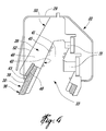
- FIG. 5 is a perspective view of a portion of the fuel manifold and fuel inlet of FIG. 3 , shown with the fuel manifold heat shield removed.
- FIG. 1 illustrates a gas turbine engine 10 of a type preferably provided for use in subsonic flight, generally comprising in serial flow communication a fan 12 through which ambient air is propelled, a multistage compressor 14 for pressurizing the air, a combustor 16 in which the compressed air is mixed with fuel and ignited for generating an annular stream of hot combustion gases, and a turbine section 18 for extracting energy from the combustion gases.
- a gas turbine engine 10 of a type preferably provided for use in subsonic flight, generally comprising in serial flow communication a fan 12 through which ambient air is propelled, a multistage compressor 14 for pressurizing the air, a combustor 16 in which the compressed air is mixed with fuel and ignited for generating an annular stream of hot combustion gases, and a turbine section 18 for extracting energy from the combustion gases.
- Fuel is injected into the combustor 16 of the gas turbine engine 10 by a fuel injection system 20 which is connected in fluid flow communication with a fuel source (not shown) and is operable to inject fuel into the combustor 16 for mixing with the compressed air from the compressor 14 and ignition of the resultant mixture.
- the fan 12 , compressor 14 , combustor 16 , and turbine 18 are preferably all concentric about a common central longitudinal axis 11 of the gas turbine engine 10 .
- axial as used herein is intended, unless otherwise indicated, to mean in a directly or axis substantially parallel to the central longitudinal axis 11 of the engine 10 .
- the fuel injection system 20 includes at least one fuel conveying member through which fuel flows.
- the fuel injection system includes an annular fuel manifold 22 which is mounted adjacent to the combustor 16 in the gas turbine engine 10 .
- the fuel manifold 22 is preferably mounted within the engine 10 by a mounting system which includes at least partially the fuel inlet assembly 30 , as will be discussed further below.
- a pair of integral attachment lugs 24 which receive pins (not shown) may also comprise part of the mounting system for engaging the fuel manifold 22 of the fuel injection system within the engine. This provides a mounting system/mechanism which allows for secure attachment of the manifold within the supporting casing.
- a plurality of fuel injecting nozzle assemblies 26 are provided about the circumference of the fuel manifold 22 .
- the fuel nozzle assemblies 26 atomize the fuel as it is injected into the combustor for ignition when mixed with the compressed air therein.
- Fuel entering the annular fuel manifold 22 via the fuel inlet assembly 30 is distributed within the manifold 22 such that fuel flow is provided to each of the fuel nozzles assemblies 26 .
- a manifold heat shield 29 may cover at least a portion of the manifold, and preferably encloses the inner fuel manifold ring 28 about substantially its entire circumference.
- the fuel manifold 22 includes the fuel manifold ring 28 , defining a solid body within which at least one fuel conveying passage 31 is defined for fuel flow communication with the fuel nozzle assemblies 26 , is enclosed within the manifold heat shield 29 .
- the fuel conveying passage(s) 31 is fed fuel from a fuel source (not shown) via a fuel inlet assembly 30 having a distal end 32 engaged with the fuel manifold 22 and a proximal end 34 mounted within a suitable supporting casing 40 , such as the gas generator casing of the gas turbine engine for example, in communication with the fuel source.
- the fuel inlet assembly 30 may comprise part of a mounting system used for supporting and locating the fuel manifold 22 within the engine, and as such helps to locate the manifold 22 adjacent the combustor 16 such that fuel is delivered thereto via the fuel nozzle assemblies 26 .
- the fuel inlet assembly 30 generally includes an inner fuel inlet tube 33 , through which fuel flows, and an outer fuel inlet heat shield 36 which surrounds the fuel inlet tube 33 along at least a portion of its length, preferably along the entire portion of its length that is exposed and extends between the casing 40 and the fuel manifold 22 .
- the fuel inlet heat shield 36 thus helps protect the fuel inlet tube 33 of the fuel inlet assembly 30 against heat damage.
- an air gap is defined between the fuel inlet tube 33 and the fuel inlet heat shield 36 , which further acts as insulation to keep the fuel flowing through the fuel inlet tube 33 cooler.
- the fuel inlet heat shield 36 is configured, in at least one embodiment, to be able to load bearing, and as such it is used to at least partially support the internal fuel manifold 22 .
- the heat shield 36 is preferably generally tubular in shape, having a tubular central body portion 38 extending between a proximal end 37 and a distal end 39 thereof.
- the proximal end 37 is suitable mounted to and supported by the casing 40 .
- the distal end 39 of the heat shield, as well as the distal end of the fuel inlet tube 33 are fastened to the fuel manifold 22 as will be described further below.
- the fuel inlet tube 33 may have a design of the type described in applicant's pending U.S. patent application Ser. No. 10/764,578, published Jul. 28, 2005, the contents of which is incorporated herein by reference.
- the distal end 32 of the fuel inlet 30 in fact comprises the distal end 39 of the heat shield 36 as well as the distal end 41 of the fuel inlet tube 33 , both of which are received within a stepped opening 42 defined within the solid body of the fuel manifold ring 28 at an inlet region 50 thereof.
- the stepped opening 42 includes an outer portion 43 which is sized to receive the distal end 39 of the fuel inlet heat shield 36 therein, and an inner portion 45 sized to receive the distal end 41 of the fuel inlet tube 33 therein a given insertion depth or distance.
- At least the lateral fit between the heat shield 36 and the fuel inlet tube 33 and the mating openings is preferably a snug or tight fit engagement.
- the distal end 39 of the fuel inlet heat shield 36 and the distal end 41 of the fuel inlet tube 33 are preferably sealingly fastened to the fuel manifold ring 28 , such as by welding, brazing or the like.
- the fuel inlet 30 is fastened to the fuel manifold 22 at the inlet region 50 (see FIG. 5 for example) of the fuel manifold ring 28 , which is located at a predetermined point about the circumference thereof.
- the inlet region 50 is located at a bottom-most point on the ring 28 .
- the inlet region 50 is reinforced relative to a remainder of the circumference of the fuel manifold ring 28 , such as to better strengthen this region in which the fuel inlet 30 is fastened and permit improved fastening using joints such as welds, brazes, etc. in this region between the fuel manifold 22 and the fuel inlet 30 .
- the reinforcement allows improved repair of the inlet region should this become necessary, as the added material provided in the fuel inlet region 50 which provided the reinforcement also allows extra material removal which might become necessary during removal of the heat shield 36 and refurbishment/repair of the brazed joints between the fuel manifold 22 and the fuel inlet 30 .
- the inlet region 50 has a thickness, at least in an axial direction, that is greater than that of a remainder of the circumference of the manifold ring 28 .
- the inlet region 50 forms a discontinuous and local increase in the cross-sectional thickness relative to this remainder of the manifold ring 28 .
- the axis thickness of the inlet region 50 is at least greater than a diameter of the distal end 39 of the fuel inlet heat shield 36 , as this distal end 39 is received therein within the outer portion 43 of the opening 42 therein.
- the thickness of at least an outer wall 48 of the enlarged inlet region 50 is sufficiently big enough to permit removal of a portion thereof (indicated at 46 in FIG. 4 ) should the brazed joint fastening the heat shield 36 to the inlet region 50 of the fuel manifold ring 28 need to be re-applied.
- the outer wall portion 48 of the enlarged reinforced inlet region 50 of the fuel manifold ring 28 preferably has a substantially constant thickness along a majority of the insertion distance of the inlet tube 33 within the opening 42 defined in the inlet region 50 .
- the entire outer wall portion 48 has a substantially constant thickness along a length thereof corresponding to the distance that the fuel inlet tube 33 is inserted within the reinforced inlet region 50 of the fuel manifold ring 28 , except for the enlarged outer portion 43 of the opening 42 which receives the heat shield 36 (which has an inner diameter greater than an outer diameter of the fuel inlet tube 33 ) therein.
- the outer surface 52 of the outer wall portion 48 is substantially parallel to the fuel inlet tube 33 .
- the fuel inlet tube 33 (and therefore the entire fuel inlet 30 ) is angled relative to a plane within which lies the fuel manifold ring 28 and which is perpendicular to the main longitudinal axis 11 of the engine (which is also coincident with a center of the annular fuel manifold ring 28 ).
- the outer surface 52 of the outer wall portion 48 is similarly angled relative to said plane. This results, as best seen in FIG. 5 , in the reinforced inlet region 50 having a triangularly shaped profile protruding outward, or more specifically downward in a direction towards the fuel inlet 30 and forward in a direction towards the fuel nozzles 26 , from adjacent regions of the fuel manifold ring 28 on either side thereof.
- the angled outer wall surface 52 of the outer wall portion 48 is sloped radially outward.
Landscapes
- Engineering & Computer Science (AREA)
- Chemical & Material Sciences (AREA)
- Combustion & Propulsion (AREA)
- Mechanical Engineering (AREA)
- General Engineering & Computer Science (AREA)
- Fuel-Injection Apparatus (AREA)
Abstract
Description
Claims (18)
Priority Applications (2)
| Application Number | Priority Date | Filing Date | Title |
|---|---|---|---|
| US11/534,243 US7743612B2 (en) | 2006-09-22 | 2006-09-22 | Internal fuel manifold and fuel inlet connection |
| CA2603619A CA2603619C (en) | 2006-09-22 | 2007-09-21 | Internal fuel manifold and fuel inlet connection |
Applications Claiming Priority (1)
| Application Number | Priority Date | Filing Date | Title |
|---|---|---|---|
| US11/534,243 US7743612B2 (en) | 2006-09-22 | 2006-09-22 | Internal fuel manifold and fuel inlet connection |
Publications (2)
| Publication Number | Publication Date |
|---|---|
| US20080072600A1 US20080072600A1 (en) | 2008-03-27 |
| US7743612B2 true US7743612B2 (en) | 2010-06-29 |
Family
ID=39190461
Family Applications (1)
| Application Number | Title | Priority Date | Filing Date |
|---|---|---|---|
| US11/534,243 Active 2029-02-07 US7743612B2 (en) | 2006-09-22 | 2006-09-22 | Internal fuel manifold and fuel inlet connection |
Country Status (2)
| Country | Link |
|---|---|
| US (1) | US7743612B2 (en) |
| CA (1) | CA2603619C (en) |
Cited By (14)
| Publication number | Priority date | Publication date | Assignee | Title |
|---|---|---|---|---|
| US20110120142A1 (en) * | 2005-01-14 | 2011-05-26 | Lev Alexander Prociw | Gas turbine engine fuel conveying member |
| US9068508B2 (en) | 2006-10-24 | 2015-06-30 | Pratt & Whitney Canada Corp. | Gas turbine internal manifold mounting arrangement |
| US9267436B2 (en) | 2013-03-18 | 2016-02-23 | General Electric Company | Fuel distribution manifold for a combustor of a gas turbine |
| US9316396B2 (en) | 2013-03-18 | 2016-04-19 | General Electric Company | Hot gas path duct for a combustor of a gas turbine |
| US9316155B2 (en) | 2013-03-18 | 2016-04-19 | General Electric Company | System for providing fuel to a combustor |
| US9322556B2 (en) | 2013-03-18 | 2016-04-26 | General Electric Company | Flow sleeve assembly for a combustion module of a gas turbine combustor |
| US9360217B2 (en) | 2013-03-18 | 2016-06-07 | General Electric Company | Flow sleeve for a combustion module of a gas turbine |
| US9383104B2 (en) | 2013-03-18 | 2016-07-05 | General Electric Company | Continuous combustion liner for a combustor of a gas turbine |
| US9400114B2 (en) | 2013-03-18 | 2016-07-26 | General Electric Company | Combustor support assembly for mounting a combustion module of a gas turbine |
| US9631812B2 (en) | 2013-03-18 | 2017-04-25 | General Electric Company | Support frame and method for assembly of a combustion module of a gas turbine |
| US9797313B2 (en) | 2014-01-16 | 2017-10-24 | Pratt & Whitney Canada Corp. | Internal manifold with fuel inlet |
| US10436445B2 (en) | 2013-03-18 | 2019-10-08 | General Electric Company | Assembly for controlling clearance between a liner and stationary nozzle within a gas turbine |
| US11371709B2 (en) | 2020-06-30 | 2022-06-28 | General Electric Company | Combustor air flow path |
| US11639795B2 (en) | 2021-05-14 | 2023-05-02 | Pratt & Whitney Canada Corp. | Tapered fuel gallery for a fuel nozzle |
Citations (29)
| Publication number | Priority date | Publication date | Assignee | Title |
|---|---|---|---|---|
| US1081950A (en) | 1913-01-27 | 1913-12-23 | Norfolk Mfg Company | Process for removing carbon deposited in internal-combustion engines. |
| US2443373A (en) | 1943-08-20 | 1948-06-15 | Victor N Borsoff | Method of removing carbon and carbonaceous matter |
| US2676461A (en) * | 1952-04-19 | 1954-04-27 | United Aircraft Corp | Head compensating valve for fuel nozzles |
| US4028888A (en) * | 1974-05-03 | 1977-06-14 | Norwalk-Turbo Inc. | Fuel distribution manifold to an annular combustion chamber |
| US4305255A (en) * | 1978-11-20 | 1981-12-15 | Rolls-Royce Limited | Combined pilot and main burner |
| US4332626A (en) | 1979-09-04 | 1982-06-01 | Ppg Industries, Inc. | Method for removing liquid residues from vessels by combustion |
| US4377420A (en) | 1980-03-06 | 1983-03-22 | United Technologies Corporation | Removal of carbonaceous material from gas turbine cavities |
| US4467610A (en) * | 1981-04-17 | 1984-08-28 | General Electric Company | Gas turbine fuel system |
| US4472133A (en) | 1982-11-24 | 1984-09-18 | Danfoss A/S | Method of operating a vapor burner for liquid fuel and vapor burner and control device for performing said method |
| US4703888A (en) | 1985-06-11 | 1987-11-03 | Isuzu Motors Limited | Cleaning apparatus for fuel burner |
| US5211005A (en) * | 1992-04-16 | 1993-05-18 | Avco Corporation | High density fuel injection manifold |
| US5771696A (en) | 1996-10-21 | 1998-06-30 | General Electric Company | Internal manifold fuel injection assembly for gas turbine |
| US5797266A (en) | 1994-11-09 | 1998-08-25 | Societe Nationale D'etude Et De Construction De Moteurs D'aviation Snecma | Device for actively controlling combustion instabilities and for decoking a fuel injector |
| US5938402A (en) | 1996-12-11 | 1999-08-17 | Asea Brown Boveri Ag | Axial turbine of a turbocharger |
| US5944483A (en) | 1995-12-29 | 1999-08-31 | Asea Brown Boveri Ag | Method and apparatus for the wet cleaning of the nozzle ring of an exhaust-gas turbocharger turbine |
| US6109038A (en) * | 1998-01-21 | 2000-08-29 | Siemens Westinghouse Power Corporation | Combustor with two stage primary fuel assembly |
| US6354085B1 (en) * | 2000-01-13 | 2002-03-12 | General Electric Company | Fuel injector with a fuel filter arrangement for a gas turbine engine |
| US6487860B2 (en) * | 2000-12-08 | 2002-12-03 | General Electric Company | Turbine engine fuel supply system |
| US6503334B2 (en) | 2001-03-14 | 2003-01-07 | Hydrochem Industrial Services, Inc. | Forced mist cleaning of combustion turbines |
| US6564555B2 (en) * | 2001-05-24 | 2003-05-20 | Allison Advanced Development Company | Apparatus for forming a combustion mixture in a gas turbine engine |
| US6672071B2 (en) * | 2001-09-27 | 2004-01-06 | General Electric Company | Methods for operating gas turbine engines |
| US6712080B1 (en) | 2002-02-15 | 2004-03-30 | The United States Of America As Represented By The Secretary Of The Army | Flushing system for removing lubricant coking in gas turbine bearings |
| US6857272B2 (en) * | 2001-07-18 | 2005-02-22 | Rolls-Royce Plc | Fuel delivery system |
| US7028484B2 (en) * | 2002-08-30 | 2006-04-18 | Pratt & Whitney Canada Corp. | Nested channel ducts for nozzle construction and the like |
| US7530231B2 (en) * | 2005-04-01 | 2009-05-12 | Pratt & Whitney Canada Corp. | Fuel conveying member with heat pipe |
| US7533531B2 (en) * | 2005-04-01 | 2009-05-19 | Pratt & Whitney Canada Corp. | Internal fuel manifold with airblast nozzles |
| US7540157B2 (en) * | 2005-06-14 | 2009-06-02 | Pratt & Whitney Canada Corp. | Internally mounted fuel manifold with support pins |
| US7559142B2 (en) * | 2006-09-26 | 2009-07-14 | Pratt & Whitney Canada Corp. | Method of manufacturing a heat shield for a fuel manifold |
| US7559201B2 (en) * | 2005-09-08 | 2009-07-14 | Pratt & Whitney Canada Corp. | Redundant fuel manifold sealing arrangement |
-
2006
- 2006-09-22 US US11/534,243 patent/US7743612B2/en active Active
-
2007
- 2007-09-21 CA CA2603619A patent/CA2603619C/en not_active Expired - Fee Related
Patent Citations (29)
| Publication number | Priority date | Publication date | Assignee | Title |
|---|---|---|---|---|
| US1081950A (en) | 1913-01-27 | 1913-12-23 | Norfolk Mfg Company | Process for removing carbon deposited in internal-combustion engines. |
| US2443373A (en) | 1943-08-20 | 1948-06-15 | Victor N Borsoff | Method of removing carbon and carbonaceous matter |
| US2676461A (en) * | 1952-04-19 | 1954-04-27 | United Aircraft Corp | Head compensating valve for fuel nozzles |
| US4028888A (en) * | 1974-05-03 | 1977-06-14 | Norwalk-Turbo Inc. | Fuel distribution manifold to an annular combustion chamber |
| US4305255A (en) * | 1978-11-20 | 1981-12-15 | Rolls-Royce Limited | Combined pilot and main burner |
| US4332626A (en) | 1979-09-04 | 1982-06-01 | Ppg Industries, Inc. | Method for removing liquid residues from vessels by combustion |
| US4377420A (en) | 1980-03-06 | 1983-03-22 | United Technologies Corporation | Removal of carbonaceous material from gas turbine cavities |
| US4467610A (en) * | 1981-04-17 | 1984-08-28 | General Electric Company | Gas turbine fuel system |
| US4472133A (en) | 1982-11-24 | 1984-09-18 | Danfoss A/S | Method of operating a vapor burner for liquid fuel and vapor burner and control device for performing said method |
| US4703888A (en) | 1985-06-11 | 1987-11-03 | Isuzu Motors Limited | Cleaning apparatus for fuel burner |
| US5211005A (en) * | 1992-04-16 | 1993-05-18 | Avco Corporation | High density fuel injection manifold |
| US5797266A (en) | 1994-11-09 | 1998-08-25 | Societe Nationale D'etude Et De Construction De Moteurs D'aviation Snecma | Device for actively controlling combustion instabilities and for decoking a fuel injector |
| US5944483A (en) | 1995-12-29 | 1999-08-31 | Asea Brown Boveri Ag | Method and apparatus for the wet cleaning of the nozzle ring of an exhaust-gas turbocharger turbine |
| US5771696A (en) | 1996-10-21 | 1998-06-30 | General Electric Company | Internal manifold fuel injection assembly for gas turbine |
| US5938402A (en) | 1996-12-11 | 1999-08-17 | Asea Brown Boveri Ag | Axial turbine of a turbocharger |
| US6109038A (en) * | 1998-01-21 | 2000-08-29 | Siemens Westinghouse Power Corporation | Combustor with two stage primary fuel assembly |
| US6354085B1 (en) * | 2000-01-13 | 2002-03-12 | General Electric Company | Fuel injector with a fuel filter arrangement for a gas turbine engine |
| US6487860B2 (en) * | 2000-12-08 | 2002-12-03 | General Electric Company | Turbine engine fuel supply system |
| US6503334B2 (en) | 2001-03-14 | 2003-01-07 | Hydrochem Industrial Services, Inc. | Forced mist cleaning of combustion turbines |
| US6564555B2 (en) * | 2001-05-24 | 2003-05-20 | Allison Advanced Development Company | Apparatus for forming a combustion mixture in a gas turbine engine |
| US6857272B2 (en) * | 2001-07-18 | 2005-02-22 | Rolls-Royce Plc | Fuel delivery system |
| US6672071B2 (en) * | 2001-09-27 | 2004-01-06 | General Electric Company | Methods for operating gas turbine engines |
| US6712080B1 (en) | 2002-02-15 | 2004-03-30 | The United States Of America As Represented By The Secretary Of The Army | Flushing system for removing lubricant coking in gas turbine bearings |
| US7028484B2 (en) * | 2002-08-30 | 2006-04-18 | Pratt & Whitney Canada Corp. | Nested channel ducts for nozzle construction and the like |
| US7530231B2 (en) * | 2005-04-01 | 2009-05-12 | Pratt & Whitney Canada Corp. | Fuel conveying member with heat pipe |
| US7533531B2 (en) * | 2005-04-01 | 2009-05-19 | Pratt & Whitney Canada Corp. | Internal fuel manifold with airblast nozzles |
| US7540157B2 (en) * | 2005-06-14 | 2009-06-02 | Pratt & Whitney Canada Corp. | Internally mounted fuel manifold with support pins |
| US7559201B2 (en) * | 2005-09-08 | 2009-07-14 | Pratt & Whitney Canada Corp. | Redundant fuel manifold sealing arrangement |
| US7559142B2 (en) * | 2006-09-26 | 2009-07-14 | Pratt & Whitney Canada Corp. | Method of manufacturing a heat shield for a fuel manifold |
Cited By (16)
| Publication number | Priority date | Publication date | Assignee | Title |
|---|---|---|---|---|
| US20110120142A1 (en) * | 2005-01-14 | 2011-05-26 | Lev Alexander Prociw | Gas turbine engine fuel conveying member |
| US8276387B2 (en) * | 2005-01-14 | 2012-10-02 | Pratt & Whitney Canada Corp. | Gas turbine engine fuel conveying member |
| US9068508B2 (en) | 2006-10-24 | 2015-06-30 | Pratt & Whitney Canada Corp. | Gas turbine internal manifold mounting arrangement |
| US9383104B2 (en) | 2013-03-18 | 2016-07-05 | General Electric Company | Continuous combustion liner for a combustor of a gas turbine |
| US9316396B2 (en) | 2013-03-18 | 2016-04-19 | General Electric Company | Hot gas path duct for a combustor of a gas turbine |
| US9316155B2 (en) | 2013-03-18 | 2016-04-19 | General Electric Company | System for providing fuel to a combustor |
| US9322556B2 (en) | 2013-03-18 | 2016-04-26 | General Electric Company | Flow sleeve assembly for a combustion module of a gas turbine combustor |
| US9360217B2 (en) | 2013-03-18 | 2016-06-07 | General Electric Company | Flow sleeve for a combustion module of a gas turbine |
| US9267436B2 (en) | 2013-03-18 | 2016-02-23 | General Electric Company | Fuel distribution manifold for a combustor of a gas turbine |
| US9400114B2 (en) | 2013-03-18 | 2016-07-26 | General Electric Company | Combustor support assembly for mounting a combustion module of a gas turbine |
| US9631812B2 (en) | 2013-03-18 | 2017-04-25 | General Electric Company | Support frame and method for assembly of a combustion module of a gas turbine |
| US10436445B2 (en) | 2013-03-18 | 2019-10-08 | General Electric Company | Assembly for controlling clearance between a liner and stationary nozzle within a gas turbine |
| US9797313B2 (en) | 2014-01-16 | 2017-10-24 | Pratt & Whitney Canada Corp. | Internal manifold with fuel inlet |
| US10294865B2 (en) | 2014-01-16 | 2019-05-21 | Pratt & Whitney Canada Corp. | Internal manifold with fuel inlet |
| US11371709B2 (en) | 2020-06-30 | 2022-06-28 | General Electric Company | Combustor air flow path |
| US11639795B2 (en) | 2021-05-14 | 2023-05-02 | Pratt & Whitney Canada Corp. | Tapered fuel gallery for a fuel nozzle |
Also Published As
| Publication number | Publication date |
|---|---|
| US20080072600A1 (en) | 2008-03-27 |
| CA2603619C (en) | 2012-07-10 |
| CA2603619A1 (en) | 2008-03-22 |
Similar Documents
| Publication | Publication Date | Title |
|---|---|---|
| US7743612B2 (en) | Internal fuel manifold and fuel inlet connection | |
| US8353166B2 (en) | Gas turbine combustor and fuel manifold mounting arrangement | |
| EP2554905B1 (en) | Assemblies and apparatus related to integrating late lean injection into combustion turbine engines | |
| JP7098300B2 (en) | A system for dissipating fuel spills in fuel supply conduit assemblies | |
| US6708495B2 (en) | Fastening a CMC combustion chamber in a turbomachine using brazed tabs | |
| US8171738B2 (en) | Gas turbine internal manifold mounting arrangement | |
| US7721546B2 (en) | Gas turbine internal manifold mounting arrangement | |
| US9464808B2 (en) | Nozzle tip assembly with secondary retention device | |
| RU2482305C2 (en) | Fuel atomiser with insulating air curtain | |
| EP1710500A1 (en) | Internal fuel manifold with airblast nozzles | |
| CN107152701B (en) | Fuel supply conduit assembly | |
| EP1108958A1 (en) | Fuel nozzle for gas turbine engine and method of assembling | |
| US8572976B2 (en) | Reduced stress internal manifold heat shield attachment | |
| US8261554B2 (en) | Fuel nozzle tip assembly | |
| US7703289B2 (en) | Internal fuel manifold having temperature reduction feature | |
| US20070163265A1 (en) | Fuel manifold inlet tube | |
| US20170328303A1 (en) | Gas turbine engine exhaust ejector/mixer | |
| CN107076421A (en) | Firm heat-insulated fuel injector for gas-turbine unit | |
| EP3214371A1 (en) | Sleeve assemblies and method of fabricating the same | |
| US7703286B2 (en) | Internal fuel manifold and fuel fairing interface | |
| US20220404020A1 (en) | Combustor having fuel sweeping structures | |
| EP4105557B1 (en) | Combustor having fuel sweeping structures | |
| EP4067746B1 (en) | Combustor having a wake energizer | |
| CN115949968A (en) | Combustor swirler to pseudo dome attachment and interface with CMC dome | |
| CA2603370C (en) | Internal fuel manifold and fuel fairing interface |
Legal Events
| Date | Code | Title | Description |
|---|---|---|---|
| AS | Assignment |
Owner name: PRATT & WHITNEY CANADA CORP., CANADA Free format text: ASSIGNMENT OF ASSIGNORS INTEREST;ASSIGNOR:MORENKO, OLEG;REEL/FRAME:018553/0471 Effective date: 20061004 Owner name: PRATT & WHITNEY CANADA CORP.,CANADA Free format text: ASSIGNMENT OF ASSIGNORS INTEREST;ASSIGNOR:MORENKO, OLEG;REEL/FRAME:018553/0471 Effective date: 20061004 |
|
| STCF | Information on status: patent grant |
Free format text: PATENTED CASE |
|
| FPAY | Fee payment |
Year of fee payment: 4 |
|
| MAFP | Maintenance fee payment |
Free format text: PAYMENT OF MAINTENANCE FEE, 8TH YEAR, LARGE ENTITY (ORIGINAL EVENT CODE: M1552) Year of fee payment: 8 |
|
| MAFP | Maintenance fee payment |
Free format text: PAYMENT OF MAINTENANCE FEE, 12TH YEAR, LARGE ENTITY (ORIGINAL EVENT CODE: M1553); ENTITY STATUS OF PATENT OWNER: LARGE ENTITY Year of fee payment: 12 |