US7739946B2 - Apparatus for brewing coffee - Google Patents

Apparatus for brewing coffee Download PDF

Info

Publication number
US7739946B2
US7739946B2 US11/352,750 US35275006A US7739946B2 US 7739946 B2 US7739946 B2 US 7739946B2 US 35275006 A US35275006 A US 35275006A US 7739946 B2 US7739946 B2 US 7739946B2
Authority
US
United States
Prior art keywords
base
housing
brewing
seal
brewing chamber
Prior art date
Legal status (The legal status is an assumption and is not a legal conclusion. Google has not performed a legal analysis and makes no representation as to the accuracy of the status listed.)
Expired - Fee Related, expires
Application number
US11/352,750
Other versions
US20070186781A1 (en
Inventor
Stephan Ruckstuhl
Current Assignee (The listed assignees may be inaccurate. Google has not performed a legal analysis and makes no representation or warranty as to the accuracy of the list.)
Eldom Rothrist AG
Original Assignee
Eldom Rothrist AG
Priority date (The priority date is an assumption and is not a legal conclusion. Google has not performed a legal analysis and makes no representation as to the accuracy of the date listed.)
Filing date
Publication date
Application filed by Eldom Rothrist AG filed Critical Eldom Rothrist AG
Priority to US11/352,750 priority Critical patent/US7739946B2/en
Assigned to ELDOM AG ROTHRIST AG reassignment ELDOM AG ROTHRIST AG ASSIGNMENT OF ASSIGNORS INTEREST (SEE DOCUMENT FOR DETAILS). Assignors: RUCKSTUHL, STEPHAN
Publication of US20070186781A1 publication Critical patent/US20070186781A1/en
Application granted granted Critical
Publication of US7739946B2 publication Critical patent/US7739946B2/en
Expired - Fee Related legal-status Critical Current
Adjusted expiration legal-status Critical

Links

Images

Classifications

    • AHUMAN NECESSITIES
    • A47FURNITURE; DOMESTIC ARTICLES OR APPLIANCES; COFFEE MILLS; SPICE MILLS; SUCTION CLEANERS IN GENERAL
    • A47JKITCHEN EQUIPMENT; COFFEE MILLS; SPICE MILLS; APPARATUS FOR MAKING BEVERAGES
    • A47J31/00Apparatus for making beverages
    • A47J31/06Filters or strainers for coffee or tea makers ; Holders therefor
    • A47J31/0647Filters or strainers for coffee or tea makers ; Holders therefor with means to adjust the brewing chamber volume to accommodate different quantities of brewing material
    • AHUMAN NECESSITIES
    • A47FURNITURE; DOMESTIC ARTICLES OR APPLIANCES; COFFEE MILLS; SPICE MILLS; SUCTION CLEANERS IN GENERAL
    • A47JKITCHEN EQUIPMENT; COFFEE MILLS; SPICE MILLS; APPARATUS FOR MAKING BEVERAGES
    • A47J31/00Apparatus for making beverages
    • A47J31/06Filters or strainers for coffee or tea makers ; Holders therefor
    • A47J31/0657Filters or strainers for coffee or tea makers ; Holders therefor for brewing coffee under pressure, e.g. for espresso machines
    • A47J31/0668Filters or strainers for coffee or tea makers ; Holders therefor for brewing coffee under pressure, e.g. for espresso machines specially adapted for cartridges
    • AHUMAN NECESSITIES
    • A47FURNITURE; DOMESTIC ARTICLES OR APPLIANCES; COFFEE MILLS; SPICE MILLS; SUCTION CLEANERS IN GENERAL
    • A47JKITCHEN EQUIPMENT; COFFEE MILLS; SPICE MILLS; APPARATUS FOR MAKING BEVERAGES
    • A47J31/00Apparatus for making beverages
    • A47J31/24Coffee-making apparatus in which hot water is passed through the filter under pressure, i.e. in which the coffee grounds are extracted under pressure
    • A47J31/34Coffee-making apparatus in which hot water is passed through the filter under pressure, i.e. in which the coffee grounds are extracted under pressure with hot water under liquid pressure
    • A47J31/36Coffee-making apparatus in which hot water is passed through the filter under pressure, i.e. in which the coffee grounds are extracted under pressure with hot water under liquid pressure with mechanical pressure-producing means
    • A47J31/3666Coffee-making apparatus in which hot water is passed through the filter under pressure, i.e. in which the coffee grounds are extracted under pressure with hot water under liquid pressure with mechanical pressure-producing means whereby the loading of the brewing chamber with the brewing material is performed by the user
    • A47J31/3676Cartridges being employed
    • A47J31/368Permeable cartridges being employed

Definitions

  • the present invention relates to an apparatus for brewing coffee, in particular for a coffee machine, having a brewing chamber which is enclosed by a housing and has a base with an outflow provided on one side and a nozzle assembly provided on the opposite side, the nozzle assembly comprising a nozzle for supplying a fluid.
  • portion packs can be introduced into a holder, which can then be inserted into a closeable housing for a brewing operation. If a relatively large quantity of coffee is to be brewed, it is possible to insert another holder in order for two portion packs to be introduced.
  • the disadvantage with this brewing apparatus is that different holders have to be used for different quantities of coffee or portion packs. This, on the one hand, involves laborious handling and, on the other hand, is inflexible since, depending on taste, finer apportioning of the quantity of coffee is desirable.
  • One of the objects of the present invention is thus to provide an apparatus for brewing coffee which is easy to handle and can flexibly accommodate different quantities of coffee or some other extraction substance.
  • the base can preferably be moved within the housing for the brewing chamber and, depending on the degree to which the brewing chamber is filled, can be fixed in different positions for the brewing operation. It is thus possible to adjust the quantity of coffee in the brewing chamber in accordance with requirements or taste, and there is no need for different components in order to change the volume of the brewing chamber.
  • the position of the base in the housing can be adjusted via a mechanism. This means that handling is easy since the mechanism can be used to predetermine the position from the outside without any manual movement of the base.
  • an all-round seal is preferably arranged between the base and housing.
  • the seal here may be retained in a brewing position with a contact pressure between the base and housing, and the contact pressure can be reduced, or done away with altogether, for the movement of the base within the housing. This is because, for the brewing operation with a certain pressure of, for example, between 2 and 5 bar, it is necessary for the brewing chamber to be sealed, for which purpose the seal is retained with contact pressure between the base and housing.
  • the contact pressure is still present, since this would just lead to wear of the seal and to high frictional forces.
  • the seal may thus be movable relative to the base, and it is possible to produce a contact pressure between the seal and housing via wedge surfaces. This ensures that a contact pressure prevails merely in the fixed position of the base or in the brewing position.
  • the base is preferably mounted in a displaceable manner on a holder and has a wedge-shaped protrusion on the side which is directed away from the brewing chamber, it being possible for the outer wedge surface of this protrusion to be positioned against a sealing lip of the seal in order to produce the contact pressure. It is thus possible for the brewing chamber to be sealed straightforwardly using only a small number of components.
  • the seal On the side which is directed away from the base, the seal may be accommodated in a cutout on the holder, this acting as a type of stop in order for it also to be possible for the seal to be secured with clamping action between the holder and the base.
  • the apparatus has a switch in order for it to be possible to adjust the volume of the brewing chamber with respect to the thickness and the number of portion packs which are to be inserted.
  • a metering device in order for it to be possible to adjust the quantity of water for the brewing operation. The consumer can thus make an individual adjustment in accordance with the strength and quantity of the coffee desired.
  • FIG. 1 shows a sectional side view of a coffee machine with an apparatus according to the invention for brewing coffee
  • FIG. 2 shows an enlarged sectional side view of the apparatus from FIG. 1 ;
  • FIG. 3 shows a plan view of the nozzle assembly of the brewing chamber from FIG. 2 ;
  • FIG. 4 shows a plan view of the base of the brewing chamber from FIG. 2 ;
  • FIG. 5 shows a perspective view of the adjusting mechanism for the brewing chamber.
  • a coffee machine 1 has a storage container 2 for clean water, the storage container being connected to a pump 5 via an outlet valve 3 and a line 4 .
  • the pump 5 By means of the pump 5 , the water can be led to a heating plate 6 which contains helical through-passages 7 in which the water can be heated.
  • a plate 8 which forms part of a nozzle assembly and in which is provided a supply line 30 for the heated water.
  • Installed on the plate 8 is a mount 9 for a sealing element 20 which is of essentially annular design and has a nozzle 11 provided in its center.
  • the heated water can flow into a brewing chamber 19 which is enclosed by a housing 10 .
  • a base 12 which is intended for bounding the brewing chamber 19 and which contains an outflow, with the result that the fluid brewed flows through a funnel-like outlet 13 to an extension arm 14 , on which an outlet opening 15 is provided for the purpose of filling coffee cups.
  • the coffee machine 1 comprises a brewing chamber 19 in which it is possible to insert one or more portion packs with coffee.
  • a cylindrical covering 16 on which is formed a handle 17 , via which the housing 10 can be released from the nozzle assembly and pivoted via an actuating mechanism, with the result that the brewing chamber 19 is filled from above.
  • the covering 16 is then closed and the housing 10 is moved into the position shown.
  • the portion packs are then emptied into a collecting container 18 in order for the brewing chamber 19 to be filled anew.
  • FIG. 2 illustrates the brewing apparatus of the coffee machine 1 in detail.
  • the sealing element 20 is of annular design and has an outer section on which are formed sealing lips 22 which butt against a radially outwardly projecting flange 21 of the housing 10 . Also formed on the outer section of the seal 20 is a sealing surface 23 which ensures sealing between the holder 9 and the seal 20 . Also formed on an inner section of the seal 20 is a further sealing lip 25 for forming a sealing surface which butts against an annular section 26 of the holder 9 .
  • the holder 9 here is provided with an annular wall which is designed in a manner similar to the geometry of the seal 20 .
  • a pressure chamber 27 is thus formed between the wall of the holder 9 and the seal 20 , and this pressure chamber is bounded by the sealing surface 23 on the outside and by the sealing surface 25 on the inside and can be subjected to pressure via a supply line 38 .
  • the supply line 38 is connected to the supply line 30 for supplying the heated water into the brewing chamber 19 and, for pressure-reducing purposes, preferably likewise has a valve with a spring, as is the case with the supply line 30 .
  • a plate-like pressure-exerting element 28 Arranged on that side of the sealing element 20 which is directed toward the brewing chamber 19 is a plate-like pressure-exerting element 28 , which is aligned by two pins 24 formed on the sealing element 20 .
  • the pressure-exerting element 28 has an inner cutout, in which the fixed nozzle 11 is accommodated.
  • the pressure-exerting element 28 here has a protrusion 29 which can be moved maximally between the nozzle 11 and a stop 37 on the holder 9 .
  • the pressure-exerting element 28 is arranged in a displaceable manner in this region and can be moved correspondingly into the brewing chamber 19 .
  • a supply line 30 which is closed by a prestressed valve 31 .
  • a spring 36 is arranged between the valve body 31 and the nozzle 11 .
  • the nozzle 11 is screw-connected to a sleeve-like protrusion of the plate 8 and has an opening 32 which opens out into the brewing chamber 19 .
  • a base 12 is 15 provided on the brewing chamber 19 , this base having a plurality of ribs 44 and a central outflow 40 .
  • the outflow 40 is closed via a valve body 41 , which is prestressed into the closed position via a spring 42 . This ensures that, within the brewing chamber 19 , the fluid can be led away via an outflow channel 43 only when a certain pressure is exceeded.
  • the base 12 is mounted on a holder 50 which is coupled to a pin 51 .
  • the pin 51 is retained in a curved element 52 of a curved guide 53 , with the result that, in the case of movement of the actuating element 17 , the curved guide 53 is moved and, via the pin 51 , the holder 50 is displaced together with the base 12 within the housing 10 .
  • the holder 50 also has a slot 56 through which leads a further pin 54 as a fulcrum for the housing 10 and central mounting for the curved guide 53 , on which a further curved element 55 is formed.
  • Pivoting of the actuating element 17 thus allows, on the one hand, pivoting of the base 12 in the housing 10 and, on the other hand, pivoting of the housing 10 itself for filling purposes, the brewing chamber 19 then having an upwardly directed opening into which one or more portion packs can be inserted.
  • the actuating element 17 is then pivoted back again and the brewing chamber 19 assumes the position shown in FIG. 1 or 2 , and the base 12 is adjusted automatically to the brewing-chamber height corresponding to the portion packs introduced.
  • a seal 45 Arranged alongside this on the base 12 is a seal 45 which has a sealing lip 66 which butts only lightly against the housing 10 , with the result that the base 12 can be displaced smoothly.
  • the seal 45 has to be accommodated with a contact pressure in the housing 10 , in order for it to be possible for a pressure of, for example, between 2 and 5 bar to build up in the brewing chamber 19 .
  • the base 12 has an all-round protrusion 60 which is of wedge-shaped design in cross section and has an outer wedge surface 61 which can be positioned against the sealing lip 66 .
  • the sealing lip 66 likewise has, in the front region, a slope 62 , which can be positioned against the wedge surface 61 .
  • the seal 45 is of cross-sectionally U-shaped design and has an accommodating means 63 for the protrusion 60 and, on the opposite side, butts against a ring 64 on a sleeve-like section 65 of the holder 50 .
  • the base 12 can be displaced smoothly in the housing 10 .
  • the base 12 is positioned in a form-fitting manner against the portion packs, but may also be forced against the same with light contact pressure, with the result that the base 12 moves in relation to the seal 45 .
  • the wedge surface 61 forces the sealing lip 66 outward and ensures reliable sealing.
  • the contact-pressure force is increased further if, upon initiation of the brewing operation, the pressure-exerting element 28 is forced, by the build-up of pressure in the pressure chamber 27 , against the portion packs, which then, in turn, force the base 12 against the seal 45 . This achieves, on the one hand, good sealing of the brewing chamber 19 and, on the other hand, a high level of tolerance in respect of the quantity of coffee.
  • FIG. 3 shows the nozzle 11 in plan view, from which the cross-shaped outlet opening 32 is visible.
  • the nozzle 11 is accommodated within the pressure-exerting element 28 , which is retained in a centered manner via pins 24 and butts against the seal 20 on the rear side.
  • the sealing lips 22 are of circular design and butt against the housing 10 .
  • FIG. 4 illustrates the base 12 of the brewing chamber 19 .
  • the ribs 44 ensure a spacing between the portion packs within the brewing chamber 19 and a base surface, with the result that the fluid can be led to the outflow 40 .
  • the base 44 is sealed on the periphery via a seal 45 .
  • FIG. 5 shows the adjusting mechanism on the coffee machine 1 .
  • a housing ring 70 is provided with markings 72 which indicate symbolically the quantity of water required.
  • a lever 71 can be used to adjust the desired quantity of water by way of the markings 72 , with the result that the pump 5 correspondingly provides just the desired volume of water.
  • a marking 74 is located on the cylindrical covering 16 and, when the brewing assembly is closed by way of the actuating element 17 , this marking indicates, via markings 73 and the housing ring 70 , how many portion packs have been introduced.
  • the markings 73 denote one or two portion packs. The user can thus freely select the quantity of coffee which is to be brewed in the brewing chamber 19 . It is, of course, also possible to provide for a finer adjustment of the size of the brewing chamber 19 , for example if there are portion packs of different thicknesses which, in accordance with the coffee taste, contain different quantities of coffee powder. In addition, it is also possible to introduce more than two portion packs into the brewing chamber 19 .
  • the adjusting mechanism for apportioning the quantity of coffee and for metering the water prefferably be designed differently and to have, for example, stepless adjustment with a quantity indicator.

Abstract

An apparatus for brewing coffee, in particular for a coffee machine (1), comprises a brewing chamber (19) which is enclosed by a housing (10) and has a base (12) with an outflow (40) provided on one side and a nozzle assembly (8, 9, 11) provided on the opposite side, the nozzle assembly (8, 9, 11) comprising a nozzle (11) for supplying a fluid. The base (12) can be moved within the housing (10) and, depending on the degree to which the brewing chamber (19) is filled, the base (12) can be fixed in different positions for the brewing operation. It is thus possible for the apparatus for brewing coffee, while being of straightforward construction, to be adapted in a flexible manner to the desired quantity of coffee.

Description

FIELD OF THE INVENTION
The present invention relates to an apparatus for brewing coffee, in particular for a coffee machine, having a brewing chamber which is enclosed by a housing and has a base with an outflow provided on one side and a nozzle assembly provided on the opposite side, the nozzle assembly comprising a nozzle for supplying a fluid.
BACKGROUND OF THE INVENTION
There are coffee machines in which portion packs can be introduced into a holder, which can then be inserted into a closeable housing for a brewing operation. If a relatively large quantity of coffee is to be brewed, it is possible to insert another holder in order for two portion packs to be introduced. The disadvantage with this brewing apparatus is that different holders have to be used for different quantities of coffee or portion packs. This, on the one hand, involves laborious handling and, on the other hand, is inflexible since, depending on taste, finer apportioning of the quantity of coffee is desirable.
SUMMARY OF THE INVENTION
One of the objects of the present invention is thus to provide an apparatus for brewing coffee which is easy to handle and can flexibly accommodate different quantities of coffee or some other extraction substance.
This object is preferably achieved by an apparatus for brewing coffee which has the features of claim 1. According to the invention, the base can preferably be moved within the housing for the brewing chamber and, depending on the degree to which the brewing chamber is filled, can be fixed in different positions for the brewing operation. It is thus possible to adjust the quantity of coffee in the brewing chamber in accordance with requirements or taste, and there is no need for different components in order to change the volume of the brewing chamber.
According to a preferred embodiment of the invention, the position of the base in the housing can be adjusted via a mechanism. This means that handling is easy since the mechanism can be used to predetermine the position from the outside without any manual movement of the base.
In order for it also to be possible to execute a brewing operation under pressure in the brewing chamber, an all-round seal is preferably arranged between the base and housing. The seal here may be retained in a brewing position with a contact pressure between the base and housing, and the contact pressure can be reduced, or done away with altogether, for the movement of the base within the housing. This is because, for the brewing operation with a certain pressure of, for example, between 2 and 5 bar, it is necessary for the brewing chamber to be sealed, for which purpose the seal is retained with contact pressure between the base and housing. For the movement of the base, in contrast, it is disadvantageous if the contact pressure is still present, since this would just lead to wear of the seal and to high frictional forces.
For the movement of the base, it is therefore advantageous if the seal is guided smoothly in the housing. The seal may thus be movable relative to the base, and it is possible to produce a contact pressure between the seal and housing via wedge surfaces. This ensures that a contact pressure prevails merely in the fixed position of the base or in the brewing position.
For mechanical shifting of the arrangement of the seal on the base, the base is preferably mounted in a displaceable manner on a holder and has a wedge-shaped protrusion on the side which is directed away from the brewing chamber, it being possible for the outer wedge surface of this protrusion to be positioned against a sealing lip of the seal in order to produce the contact pressure. It is thus possible for the brewing chamber to be sealed straightforwardly using only a small number of components. On the side which is directed away from the base, the seal may be accommodated in a cutout on the holder, this acting as a type of stop in order for it also to be possible for the seal to be secured with clamping action between the holder and the base.
For easy handling, the apparatus has a switch in order for it to be possible to adjust the volume of the brewing chamber with respect to the thickness and the number of portion packs which are to be inserted. For coordination which is as flexible as possible, it is also possible to provide a metering device in order for it to be possible to adjust the quantity of water for the brewing operation. The consumer can thus make an individual adjustment in accordance with the strength and quantity of the coffee desired.
BRIEF DESCRIPTION OF THE DRAWINGS
The invention is explained in more detail hereinbelow by way of an exemplary embodiment (which shall not be construed to limit the scope of the invention as defined in the appended claims) and with reference to the attached drawings, in which:
FIG. 1 shows a sectional side view of a coffee machine with an apparatus according to the invention for brewing coffee;
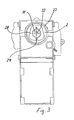
FIG. 2 shows an enlarged sectional side view of the apparatus from FIG. 1;
FIG. 3 shows a plan view of the nozzle assembly of the brewing chamber from FIG. 2;
FIG. 4 shows a plan view of the base of the brewing chamber from FIG. 2; and
FIG. 5 shows a perspective view of the adjusting mechanism for the brewing chamber.
DESCRIPTION OF EXAMPLE EMBODIMENTS
A coffee machine 1 has a storage container 2 for clean water, the storage container being connected to a pump 5 via an outlet valve 3 and a line 4. By means of the pump 5, the water can be led to a heating plate 6 which contains helical through-passages 7 in which the water can be heated. Provided alongside this is a plate 8 which forms part of a nozzle assembly and in which is provided a supply line 30 for the heated water. Installed on the plate 8 is a mount 9 for a sealing element 20 which is of essentially annular design and has a nozzle 11 provided in its center.
Via the nozzle 11, the heated water can flow into a brewing chamber 19 which is enclosed by a housing 10. Provided on the opposite side of the nozzle 11 is a base 12 which is intended for bounding the brewing chamber 19 and which contains an outflow, with the result that the fluid brewed flows through a funnel-like outlet 13 to an extension arm 14, on which an outlet opening 15 is provided for the purpose of filling coffee cups.
The coffee machine 1 comprises a brewing chamber 19 in which it is possible to insert one or more portion packs with coffee. Provided for this purpose is a cylindrical covering 16 on which is formed a handle 17, via which the housing 10 can be released from the nozzle assembly and pivoted via an actuating mechanism, with the result that the brewing chamber 19 is filled from above. The covering 16 is then closed and the housing 10 is moved into the position shown. Following the brewing operation, the portion packs are then emptied into a collecting container 18 in order for the brewing chamber 19 to be filled anew. For the coffee machine 1 shown, however, it is also possible to use other actuating mechanisms in order to fill the brewing apparatus with one or more portion packs.
FIG. 2 illustrates the brewing apparatus of the coffee machine 1 in detail.
The sealing element 20 is of annular design and has an outer section on which are formed sealing lips 22 which butt against a radially outwardly projecting flange 21 of the housing 10. Also formed on the outer section of the seal 20 is a sealing surface 23 which ensures sealing between the holder 9 and the seal 20. Provided on an inner section of the seal 20 is a further sealing lip 25 for forming a sealing surface which butts against an annular section 26 of the holder 9. The holder 9 here is provided with an annular wall which is designed in a manner similar to the geometry of the seal 20. A pressure chamber 27 is thus formed between the wall of the holder 9 and the seal 20, and this pressure chamber is bounded by the sealing surface 23 on the outside and by the sealing surface 25 on the inside and can be subjected to pressure via a supply line 38. The supply line 38 is connected to the supply line 30 for supplying the heated water into the brewing chamber 19 and, for pressure-reducing purposes, preferably likewise has a valve with a spring, as is the case with the supply line 30.
Arranged on that side of the sealing element 20 which is directed toward the brewing chamber 19 is a plate-like pressure-exerting element 28, which is aligned by two pins 24 formed on the sealing element 20. The pressure-exerting element 28 has an inner cutout, in which the fixed nozzle 11 is accommodated. The pressure-exerting element 28 here has a protrusion 29 which can be moved maximally between the nozzle 11 and a stop 37 on the holder 9. The pressure-exerting element 28 is arranged in a displaceable manner in this region and can be moved correspondingly into the brewing chamber 19.
Once the fluid has been heated, it can flow through a supply line 30 which is closed by a prestressed valve 31. For this purpose, a spring 36 is arranged between the valve body 31 and the nozzle 11. The nozzle 11 is screw-connected to a sleeve-like protrusion of the plate 8 and has an opening 32 which opens out into the brewing chamber 19.
On the opposite side of the nozzle 11, a base 12 is 15 provided on the brewing chamber 19, this base having a plurality of ribs 44 and a central outflow 40. The outflow 40 is closed via a valve body 41, which is prestressed into the closed position via a spring 42. This ensures that, within the brewing chamber 19, the fluid can be led away via an outflow channel 43 only when a certain pressure is exceeded.
The base 12 is mounted on a holder 50 which is coupled to a pin 51. The pin 51 is retained in a curved element 52 of a curved guide 53, with the result that, in the case of movement of the actuating element 17, the curved guide 53 is moved and, via the pin 51, the holder 50 is displaced together with the base 12 within the housing 10. The holder 50 also has a slot 56 through which leads a further pin 54 as a fulcrum for the housing 10 and central mounting for the curved guide 53, on which a further curved element 55 is formed. Pivoting of the actuating element 17 thus allows, on the one hand, pivoting of the base 12 in the housing 10 and, on the other hand, pivoting of the housing 10 itself for filling purposes, the brewing chamber 19 then having an upwardly directed opening into which one or more portion packs can be inserted. The actuating element 17 is then pivoted back again and the brewing chamber 19 assumes the position shown in FIG. 1 or 2, and the base 12 is adjusted automatically to the brewing-chamber height corresponding to the portion packs introduced.
Arranged alongside this on the base 12 is a seal 45 which has a sealing lip 66 which butts only lightly against the housing 10, with the result that the base 12 can be displaced smoothly. For the brewing operation, however, the seal 45 has to be accommodated with a contact pressure in the housing 10, in order for it to be possible for a pressure of, for example, between 2 and 5 bar to build up in the brewing chamber 19. For this purpose, on the side which is directed away from the brewing chamber 19, the base 12 has an all-round protrusion 60 which is of wedge-shaped design in cross section and has an outer wedge surface 61 which can be positioned against the sealing lip 66. The sealing lip 66 likewise has, in the front region, a slope 62, which can be positioned against the wedge surface 61. The seal 45 is of cross-sectionally U-shaped design and has an accommodating means 63 for the protrusion 60 and, on the opposite side, butts against a ring 64 on a sleeve-like section 65 of the holder 50.
As long as the spring-assisted spacing between the base 12 and seal 45 is present, the base 12 can be displaced smoothly in the housing 10. For the brewing operation, the base 12 is positioned in a form-fitting manner against the portion packs, but may also be forced against the same with light contact pressure, with the result that the base 12 moves in relation to the seal 45. By virtue of this movement, the wedge surface 61 forces the sealing lip 66 outward and ensures reliable sealing. The contact-pressure force is increased further if, upon initiation of the brewing operation, the pressure-exerting element 28 is forced, by the build-up of pressure in the pressure chamber 27, against the portion packs, which then, in turn, force the base 12 against the seal 45. This achieves, on the one hand, good sealing of the brewing chamber 19 and, on the other hand, a high level of tolerance in respect of the quantity of coffee.
FIG. 3 shows the nozzle 11 in plan view, from which the cross-shaped outlet opening 32 is visible. The nozzle 11 is accommodated within the pressure-exerting element 28, which is retained in a centered manner via pins 24 and butts against the seal 20 on the rear side. The sealing lips 22 are of circular design and butt against the housing 10.
FIG. 4 illustrates the base 12 of the brewing chamber 19. The ribs 44 ensure a spacing between the portion packs within the brewing chamber 19 and a base surface, with the result that the fluid can be led to the outflow 40. The base 44 is sealed on the periphery via a seal 45.
FIG. 5 shows the adjusting mechanism on the coffee machine 1. A housing ring 70 is provided with markings 72 which indicate symbolically the quantity of water required. A lever 71 can be used to adjust the desired quantity of water by way of the markings 72, with the result that the pump 5 correspondingly provides just the desired volume of water.
Furthermore, a marking 74 is located on the cylindrical covering 16 and, when the brewing assembly is closed by way of the actuating element 17, this marking indicates, via markings 73 and the housing ring 70, how many portion packs have been introduced. The markings 73 denote one or two portion packs. The user can thus freely select the quantity of coffee which is to be brewed in the brewing chamber 19. It is, of course, also possible to provide for a finer adjustment of the size of the brewing chamber 19, for example if there are portion packs of different thicknesses which, in accordance with the coffee taste, contain different quantities of coffee powder. In addition, it is also possible to introduce more than two portion packs into the brewing chamber 19.
It is, of course, also possible for the adjusting mechanism for apportioning the quantity of coffee and for metering the water to be designed differently and to have, for example, stepless adjustment with a quantity indicator.

Claims (11)

1. An apparatus for brewing coffee, in particular for a coffee machine, having a brewing chamber which is enclosed by a housing and has a base with an outflow provided on one side and a nozzle assembly provided on the opposite side, the nozzle assembly comprising a nozzle for supplying a fluid, wherein the base can be moved within the housing and, depending on the degree to which the brewing chamber is filled, can be fixed in different positions for the brewing operation, wherein the base is mounted in a displaceable manner on a holder and has a wedge-shaped protrusion on the side which is directed away from the brewing chamber, and wherein an all-round seal is arranged between the base and housing, the seal being retained in a brewing position with a contact pressure between the base and housing, it being possible for the outer wedge surface of this protrusion to be positioned against a sealing lip of the seal in order to produce the contact pressure.
2. The apparatus as claimed in claim 1, wherein the position of the base in the housing can be adjusted automatically via a mechanism.
3. The apparatus as claimed in claim 1, wherein an all-round seal is arranged between the base and housing.
4. The apparatus as claimed in claim 3, wherein the seal is retained in a brewing position with a contact pressure between the base and housing, and the contact pressure is at least reduced for the movement of the base within the housing, the seal only butting lightly against the housing for the movement of the base.
5. The apparatus as claimed in claim 4, wherein the seal is movable relative to the base, and it is possible to produce a contact pressure between the seal and housing via wedge surfaces.
6. The apparatus as claimed in claim 1, wherein, on the side which is directed away from the base, the seal is accommodated in a cutout on a holder.
7. The apparatus as claimed in claim 1, wherein the nozzle assembly has a pressure-exerting element which, upon initiation of the brewing operation, can be moved hydraulically in the direction of the brewing chamber, portion packs contained in the brewing chamber thus being forced in the direction of the base.
8. The apparatus as claimed in claim 1, wherein a marking is provided in order to indicate the volume of the brewing chamber with respect to the thickness and the number of portion packs inserted.
9. The apparatus as claimed in claim 1, wherein a metering device is provided in order for it to be possible to adjust the quantity of water for the brewing operation.
10. The apparatus as claimed in claim 6, wherein a spring is provided between the base and the holder in order to subject a seal to stressing by a movement of the base relative to the holder.
11. The apparatus as claimed in claim 2, wherein the base can be automatically fixed in different positions, without any preliminary adjustment, within the housing for the brewing operation via curved elements, levers, guide means or other mechanisms.
US11/352,750 2006-02-13 2006-02-13 Apparatus for brewing coffee Expired - Fee Related US7739946B2 (en)

Priority Applications (1)

Application Number Priority Date Filing Date Title
US11/352,750 US7739946B2 (en) 2006-02-13 2006-02-13 Apparatus for brewing coffee

Applications Claiming Priority (1)

Application Number Priority Date Filing Date Title
US11/352,750 US7739946B2 (en) 2006-02-13 2006-02-13 Apparatus for brewing coffee

Publications (2)

Publication Number Publication Date
US20070186781A1 US20070186781A1 (en) 2007-08-16
US7739946B2 true US7739946B2 (en) 2010-06-22

Family

ID=38366990

Family Applications (1)

Application Number Title Priority Date Filing Date
US11/352,750 Expired - Fee Related US7739946B2 (en) 2006-02-13 2006-02-13 Apparatus for brewing coffee

Country Status (1)

Country Link
US (1) US7739946B2 (en)

Cited By (2)

* Cited by examiner, † Cited by third party
Publication number Priority date Publication date Assignee Title
US20120121779A1 (en) * 2010-11-15 2012-05-17 Conair Corporation Brewed beverage appliance and method
US20140318381A1 (en) * 2011-12-01 2014-10-30 Nestec S.A. Beverage preparation machine

Citations (12)

* Cited by examiner, † Cited by third party
Publication number Priority date Publication date Assignee Title
EP0097129A1 (en) 1982-06-11 1983-12-28 Alfredo Cavalli Percolator assembly supporting structure, particularly for domestic automatic coffee percolators
US4796521A (en) * 1986-10-31 1989-01-10 Lucio Grossi Compact automatic coffee-making machine more particularly for domestic use
US5302407A (en) 1992-03-19 1994-04-12 Cosmec S.R.L. Method and apparatus for preparing coffee beverages
FR2766346A1 (en) 1998-09-17 1999-01-29 Moulinex Sa Filter carrier for expresso-type coffee making machine
US6021706A (en) * 1996-01-25 2000-02-08 Seguenot; Gerard Filter holder for an espresso-type coffee machine
US6192786B1 (en) 1998-07-16 2001-02-27 Maxs Ag Espresso brewing head unit
USRE37173E1 (en) * 1995-07-20 2001-05-15 Harry D. Jefferson, Jr. Coffee and tea brewing apparatus and system
US6634280B2 (en) * 2000-05-31 2003-10-21 Rancilio Macchine Per Caffe' S.P.A. Coffee making machine
US6857355B2 (en) * 2000-07-26 2005-02-22 Seb S.A. Filter-holder for espresso coffee machine
EP1625814A1 (en) 2004-08-14 2006-02-15 Melitta France SAS Device for brewing coffee
US7216582B2 (en) * 2000-11-28 2007-05-15 Nestec S.A. Percolating device
US7337704B2 (en) * 2005-05-25 2008-03-04 Sunbeam Products, Inc. Single serve beverage maker with coordinated heating and pumping periods

Patent Citations (12)

* Cited by examiner, † Cited by third party
Publication number Priority date Publication date Assignee Title
EP0097129A1 (en) 1982-06-11 1983-12-28 Alfredo Cavalli Percolator assembly supporting structure, particularly for domestic automatic coffee percolators
US4796521A (en) * 1986-10-31 1989-01-10 Lucio Grossi Compact automatic coffee-making machine more particularly for domestic use
US5302407A (en) 1992-03-19 1994-04-12 Cosmec S.R.L. Method and apparatus for preparing coffee beverages
USRE37173E1 (en) * 1995-07-20 2001-05-15 Harry D. Jefferson, Jr. Coffee and tea brewing apparatus and system
US6021706A (en) * 1996-01-25 2000-02-08 Seguenot; Gerard Filter holder for an espresso-type coffee machine
US6192786B1 (en) 1998-07-16 2001-02-27 Maxs Ag Espresso brewing head unit
FR2766346A1 (en) 1998-09-17 1999-01-29 Moulinex Sa Filter carrier for expresso-type coffee making machine
US6634280B2 (en) * 2000-05-31 2003-10-21 Rancilio Macchine Per Caffe' S.P.A. Coffee making machine
US6857355B2 (en) * 2000-07-26 2005-02-22 Seb S.A. Filter-holder for espresso coffee machine
US7216582B2 (en) * 2000-11-28 2007-05-15 Nestec S.A. Percolating device
EP1625814A1 (en) 2004-08-14 2006-02-15 Melitta France SAS Device for brewing coffee
US7337704B2 (en) * 2005-05-25 2008-03-04 Sunbeam Products, Inc. Single serve beverage maker with coordinated heating and pumping periods

Cited By (4)

* Cited by examiner, † Cited by third party
Publication number Priority date Publication date Assignee Title
US20120121779A1 (en) * 2010-11-15 2012-05-17 Conair Corporation Brewed beverage appliance and method
US8573115B2 (en) * 2010-11-15 2013-11-05 Conair Corporation Brewed beverage appliance and method
US20140318381A1 (en) * 2011-12-01 2014-10-30 Nestec S.A. Beverage preparation machine
US9301640B2 (en) * 2011-12-01 2016-04-05 Nestec S.A. Beverage preparation machine

Also Published As

Publication number Publication date
US20070186781A1 (en) 2007-08-16

Similar Documents

Publication Publication Date Title
CA2583395C (en) Dispenser
US8776672B2 (en) Brewing device for a coffee machine
CA2684669C (en) Improvements in or relating to beverage preparation machines and beverage cartridges
US7942093B2 (en) Automatic brewed beverage dispenser comprising an infused product ejecting device
US8950317B2 (en) Beverage preparation machines
CA2684941C (en) Improvements in or relating to beverage preparation machines
EP1736091B1 (en) Apparatus for wetting a cleaning tool
WO2006005756A1 (en) Percolator for producing a beverage from powdered material in a container
US20110185909A1 (en) Brewing device for a coffee machine
EP0231156A1 (en) A manually operated coffee-making machine
GB2463350A (en) Improvements in or relating to beverage preparation machines
CN108882803A (en) Distribution group for the espresso coffee machine with preceding insertion filter retainer
US7739946B2 (en) Apparatus for brewing coffee
WO2011111287A1 (en) Coffee maker
CA2536284A1 (en) Apparatus for brewing coffee
US7278349B2 (en) Carafe with outlet in handle
US7673560B2 (en) Brewing apparatus for a coffee machine
EP3406164B1 (en) Coffee machine comprising a movable chute for introducing a cleaning tablet
EP0037824A1 (en) Drink dispenser.
US7600466B2 (en) Apparatus for filling and emptying a brewing chamber
EP4179927A1 (en) Dispensing device for dispensing a hot drink
CA2536287A1 (en) Brewing apparatus for a coffee machine
CA2571698A1 (en) Brewing apparatus for a coffee machine
EP3593678B1 (en) Coffee machine
WO2021093989A1 (en) Ecological coffee machine

Legal Events

Date Code Title Description
AS Assignment

Owner name: ELDOM AG ROTHRIST AG, SWITZERLAND

Free format text: ASSIGNMENT OF ASSIGNORS INTEREST;ASSIGNOR:RUCKSTUHL, STEPHAN;REEL/FRAME:017912/0263

Effective date: 20060317

Owner name: ELDOM AG ROTHRIST AG,SWITZERLAND

Free format text: ASSIGNMENT OF ASSIGNORS INTEREST;ASSIGNOR:RUCKSTUHL, STEPHAN;REEL/FRAME:017912/0263

Effective date: 20060317

FEPP Fee payment procedure

Free format text: PAYOR NUMBER ASSIGNED (ORIGINAL EVENT CODE: ASPN); ENTITY STATUS OF PATENT OWNER: LARGE ENTITY

REMI Maintenance fee reminder mailed
LAPS Lapse for failure to pay maintenance fees
STCH Information on status: patent discontinuation

Free format text: PATENT EXPIRED DUE TO NONPAYMENT OF MAINTENANCE FEES UNDER 37 CFR 1.362

FP Lapsed due to failure to pay maintenance fee

Effective date: 20140622