US7738700B2 - Image processing apparatus, control method therefor, and program - Google Patents
Image processing apparatus, control method therefor, and program Download PDFInfo
- Publication number
- US7738700B2 US7738700B2 US11/331,311 US33131106A US7738700B2 US 7738700 B2 US7738700 B2 US 7738700B2 US 33131106 A US33131106 A US 33131106A US 7738700 B2 US7738700 B2 US 7738700B2
- Authority
- US
- United States
- Prior art keywords
- comparison
- image
- region
- comparison region
- estimate value
- Prior art date
- Legal status (The legal status is an assumption and is not a legal conclusion. Google has not performed a legal analysis and makes no representation as to the accuracy of the status listed.)
- Expired - Fee Related, expires
Links
Images


Classifications
-
- G—PHYSICS
- G06—COMPUTING OR CALCULATING; COUNTING
- G06T—IMAGE DATA PROCESSING OR GENERATION, IN GENERAL
- G06T7/00—Image analysis
- G06T7/30—Determination of transform parameters for the alignment of images, i.e. image registration
-
- G—PHYSICS
- G06—COMPUTING OR CALCULATING; COUNTING
- G06V—IMAGE OR VIDEO RECOGNITION OR UNDERSTANDING
- G06V10/00—Arrangements for image or video recognition or understanding
- G06V10/40—Extraction of image or video features
- G06V10/50—Extraction of image or video features by performing operations within image blocks; by using histograms, e.g. histogram of oriented gradients [HoG]; by summing image-intensity values; Projection analysis
- G06V10/507—Summing image-intensity values; Histogram projection analysis
-
- G—PHYSICS
- G06—COMPUTING OR CALCULATING; COUNTING
- G06T—IMAGE DATA PROCESSING OR GENERATION, IN GENERAL
- G06T2207/00—Indexing scheme for image analysis or image enhancement
- G06T2207/20—Special algorithmic details
- G06T2207/20021—Dividing image into blocks, subimages or windows
-
- G—PHYSICS
- G06—COMPUTING OR CALCULATING; COUNTING
- G06T—IMAGE DATA PROCESSING OR GENERATION, IN GENERAL
- G06T2207/00—Indexing scheme for image analysis or image enhancement
- G06T2207/20—Special algorithmic details
- G06T2207/20068—Projection on vertical or horizontal image axis
Definitions
- the present invention relates to an image processing apparatus which executes image processing for determining a comparison region used to perform similarity comparison between a comparison source image and a comparison destination image, a control method therefor, and a program.
- the translation amount and homothetic ratio are estimated for combinations of the peak positions of the projection waveform of a reference image and those of the projection waveform of a check image.
- Estimate homothetic transformation parameters including translation amounts and homothetic ratios which are estimated for respective combinations are generated.
- a parameter of high likelihood is determined as a homothetic transformation parameter.
- This calculation method is preferably employed to efficiently implement similarity comparison.
- the present invention has been made to overcome the conventional drawbacks, and has as its object to provide an image processing apparatus capable of efficiently executing similarity comparison between images at high precision, a control method therefor, and a program.
- an image processing apparatus which executes image processing of determining a comparison region used to perform similarity comparison between a comparison source image and a comparison destination image, comprising:
- histogram calculation means for calculating horizontal and vertical projection histograms of an image to be processed
- object size calculation means for calculating autocorrelation values of the horizontal and vertical projection histograms which are calculated by the histogram calculation means, and calculating horizontal and vertical object sizes until the autocorrelation values decrease to predetermined thresholds;
- aspect ratio estimate value calculation means for calculating an aspect ratio estimate value of a circumscribed rectangle of an object serving as a comparison region candidate in the image to be processed, on the basis of calculation results of the object size calculation means;
- comparison region determination means for correcting the comparison region candidate on the basis of the aspect ratio estimate value calculated by the aspect ratio estimate value calculation means, and determining a final comparison region.
- the apparatus further comprises homothetic ratio calculation means for calculating a homothetic ratio estimate value of circumscribed rectangles of objects serving as comparison region candidates in the comparison source image and the comparison destination image on the basis of the calculation results of the object size calculation means,
- comparison region determination means corrects the comparison region candidate on the basis of the aspect ratio estimate value calculated by the aspect ratio estimate value calculation means and the homothetic ratio estimate value calculated by the homothetic ratio calculation means, and determines the final comparison region.
- the homothetic ratio calculation means calculates a first homothetic ratio estimate value in a horizontal direction and a second homothetic ratio estimate value in a vertical direction between the circumscribed rectangles of the objects serving as the comparison region candidates in the comparison source image and the comparison destination image on the basis of the calculation results of the object size calculation means.
- the aspect ratio estimate value calculation means calculates a first aspect ratio estimate value of a circumscribed rectangle of an object serving as a comparison region candidate in the comparison source image and a second aspect ratio estimate value of a circumscribed rectangle of an object serving as a comparison region candidate in the comparison destination image on the basis of the calculation results of the object size calculation means.
- an image processing apparatus which executes image processing of determining a comparison region used to perform similarity comparison between a comparison source image and a comparison destination image, comprising:
- calculation means for calculating projection histograms of the comparison source image and the comparison destination image
- comparison region candidate determination means for determining comparison region candidates used to perform similarity comparison between the comparison source image and the comparison destination image on the basis of the projection histograms calculated by the calculation means
- comparison region determination means for determining a final comparison region by correcting the comparison region candidates on the basis of at least one of aspect ratio estimate values of circumscribed rectangles of objects serving as comparison region candidates in the comparison source image and the comparison destination image that are calculated on the basis of the projection histograms calculated by the calculation means, and a homothetic ratio estimate value of the circumscribed rectangles of the objects serving as the comparison region candidates in the comparison source image and the comparison destination image.
- the comparison region determination means sets, of the comparison region candidates in the comparison source image and the comparison destination image, as an image ⁇ , an image A whose circumscribed rectangle of the object is known in advance to be likely to have a value different from an original value,
- the comparison region determination means sets each of the comparison region candidates in the comparison source image and the comparison destination image as the image ⁇ or the image ⁇ on the basis of an average of a first aspect ratio estimate value of the circumscribed rectangle of the object in the comparison source image, and a second aspect ratio estimate value of the circumscribed rectangle of the object in the comparison destination image.
- the homothetic ratio estimate value includes a first homothetic ratio estimate value in a horizontal direction and a second homothetic ratio estimate value in a vertical direction for the circumscribed rectangle of the object, and
- the comparison region determination means uses one of the image ⁇ and the image ⁇ to correct the other image on the basis of a difference between the first homothetic ratio estimate value and the second homothetic ratio estimate value.
- the comparison region determination means uses one of a size of the image ⁇ and a size of the image ⁇ to correct the other image on the basis of a first absolute value of a difference between the first homothetic ratio estimate value and a first homothetic ratio in the horizontal direction between the comparison region candidates in the comparison source image and the comparison destination image, and a second absolute value of a difference between the second homothetic ratio estimate value and a second homothetic ratio in the vertical direction between the comparison region candidates in the comparison source image and the comparison destination image.
- the comparison region determination means uses one of the first homothetic ratio estimate value and the second homothetic ratio estimate value and one of the size of the image ⁇ and the size of the image ⁇ to correct the other image on the basis of a first homothetic ratio, a second homothetic ratio, the first homothetic ratio estimate value, and the second homothetic ratio estimate value.
- the apparatus further comprises comparison means for executing similarity comparison between the comparison source image and the comparison destination image by using the comparison region determined by the comparison region determination means.
- the apparatus further comprises control means for canceling comparison by the comparison means on the basis of the first homothetic ratio, the second homothetic ratio, the first homothetic ratio estimate value, and the second homothetic ratio estimate value.
- the apparatus further comprises optimization means for optimizing coordinates of the comparison region determined by the comparison region determination means.
- the optimization means comprises
- area difference calculation means for calculating an area difference between an area of one of the circumscribed rectangles of the objects serving as the comparison region candidates in the comparison source image and the comparison destination image that is calculated on the basis of the projection histogram calculated by the calculation means, and an area of the comparison region determined by the comparison region determination means, and
- determination means for determining the coordinates of the comparison region on the basis of the area difference calculated by the area difference calculation means by using one of the circumscribed rectangles of the objects serving as the comparison region candidates in the comparison source image and the comparison destination image.
- the determination means determines, as the coordinates of the comparison region, coordinates of an arbitrary region in the circumscribed rectangle of the object which has the area of the comparison region determined by the comparison region determination means and is used for calculation by the area difference calculation means.
- the determination means comprises
- the determination means determines coordinates of the comparison region candidate selected by the selection means as the coordinates of the comparison region.
- the foregoing object is attained by providing a method of controlling an image processing apparatus which executes image processing of determining a comparison region used to perform similarity comparison between a comparison source image and a comparison destination image, comprising:
- a histogram calculation step of calculating horizontal and vertical projection histograms of an image to be processed
- an aspect ratio estimate value calculation step of calculating an aspect ratio estimate value of a circumscribed rectangle of an object serving as a comparison region candidate in the image to be processed on the basis of calculation results of the object size calculation step;
- a comparison region determination step of correcting the comparison region candidate on the basis of the aspect ratio estimate value calculated in the aspect ratio estimate value calculation step, and determining a final comparison region.
- the foregoing object is attained by providing a method of controlling an image processing apparatus which executes image processing of determining a comparison region used to perform similarity comparison between a comparison source image and a comparison destination image, comprising:
- comparison region candidate determination step of determining comparison region candidates used to perform similarity comparison between the comparison source image and the comparison destination image on the basis of the projection histograms calculated in the calculation step
- a comparison region determination step of determining a final comparison region by correcting the comparison region candidates on the basis of at least one of aspect ratio estimate values of circumscribed rectangles of objects serving as comparison region candidates in the comparison source image and the comparison destination image that are calculated on the basis of the projection histograms calculated in the calculation step, and a homothetic ratio estimate value of the circumscribed rectangles of the objects serving as the comparison region candidates in the comparison source image and the comparison destination image.
- the foregoing object is attained by providing program for causing a computer to control an image processing apparatus which executes image processing of determining a comparison region used to perform similarity comparison between a comparison source image and a comparison destination image, characterized by causing the computer to execute
- a histogram calculation step of calculating horizontal and vertical projection histograms of an image to be processed
- an object size calculation step of calculating autocorrelation values of the horizontal and vertical projection histograms which are calculated in the histogram calculation step, and calculating horizontal and vertical object sizes until the autocorrelation values decrease to predetermined thresholds
- an aspect ratio estimate value calculation step of calculating an aspect ratio estimate value of a circumscribed rectangle of an object serving as a comparison region candidate in the image to be processed on the basis of calculation results of the object size calculation step
- a comparison region determination step of correcting the comparison region candidate on the basis of the aspect ratio estimate value calculated in the aspect ratio estimate value calculation step, and determining a final comparison region.
- the foregoing object is attained by providing program for causing a computer to control an image processing apparatus which executes image processing of determining a comparison region used to perform similarity comparison between a comparison source image and a comparison destination image, characterized by causing the computer to execute
- comparison region candidate determination step of determining comparison region candidates used to perform similarity comparison between the comparison source image and the comparison destination image on the basis of the projection histograms calculated in the calculation step
- a comparison region determination step of determining a final comparison region by correcting the comparison region candidates on the basis of at least one of aspect ratio estimate values of circumscribed rectangles of objects serving as comparison region candidates in the comparison source image and the comparison destination image that are calculated on the basis of the projection histograms calculated in the calculation step, and a homothetic ratio estimate value of the circumscribed rectangles of the objects serving as the comparison region candidates in the comparison source image and the comparison destination image.
- FIG. 1 is a view showing an example of the arrangement of an image processing apparatus according to the first embodiment of the present invention
- FIG. 2 is a flowchart showing an outline of processing by the image processing apparatus according to the first embodiment of the present invention
- FIG. 3 is a flowchart showing details of processing in step S 202 according to the first embodiment of the present invention
- FIG. 4 is a view for explaining a comparison region determination method according to the first embodiment of the present invention.
- FIG. 5 is a graph for explaining object size determination based on the normalized autocorrelation of the projection histogram according to the first embodiment of the present invention
- FIG. 6A is a flowchart showing details of processing in step S 314 according to the first embodiment of the present invention.
- FIG. 6B is a flowchart showing details of processing in step S 314 according to the first embodiment of the present invention.
- FIG. 7 is a table for explaining caution to be exercised in block division according to the first embodiment of the present invention.
- FIG. 8 is a flowchart showing details of comparison processing according to the first embodiment of the present invention.
- FIG. 9 is a view showing an example of a position shifting pattern according to the first embodiment of the present invention.
- FIG. 10 is a view showing an example of position shifting according to the first embodiment of the present invention.
- FIG. 11 is a view for explaining a position correction amount calculation method according to the first embodiment of the present invention.
- FIG. 12 is a flowchart showing details of difference image generation processing according to the first embodiment of the present invention.
- FIG. 13 is a flowchart showing an example of details of determination processing according to the first embodiment of the present invention.
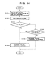
- FIG. 14 is a flowchart showing another example of details of determination processing according to the first embodiment of the present invention.
- FIG. 15 is a flowchart showing still another example of details of determination processing according to the first embodiment of the present invention.
- FIG. 16 is a flowchart showing an outline of processing by an image processing apparatus according to the second embodiment of the present invention.
- FIG. 17 is a view for explaining a case wherein a plurality of comparison region candidates are set according to the second embodiment of the present invention.
- FIG. 18 is a flowchart showing details of optimization processing in step S 203 a according to the second embodiment of the present invention.
- image data scanned in copying an original is stored in a storage device.
- Processing comparison processing for details of image data
- searching image data scanned in copying an original having an annotation, stain, or the like for corresponding image data of the original is executed to output the searched image data.
- the first embodiment will be described by exemplifying this arrangement.
- FIG. 1 is a view showing an example of the arrangement of an image processing apparatus according to the first embodiment of the present invention.
- reference numeral 101 denotes a CPU which executes various arithmetic and control operations in image processing (or image search processing) according to the first embodiment.
- Reference numeral 102 denotes a ROM which stores various permanent data and a boot program executed at startup of the image processing apparatus.
- Reference numeral 103 denotes a RAM which stores control programs to be processed by the CPU 101 and provides a work area used to execute various control operations by the CPU 101 .
- the RAM 103 stores, in its storage area, a comparison determination module 103 a serving as a program for image processing of the present invention, a comparison source image, a comparison destination image, a scaling (enlarging/reducing) image, a work area for performing various processes, and processing information on processing (processing parameters, various counter values, thresholds, and the like).
- Reference numeral 104 denotes a keyboard; and 105 , a mouse which provides various input operation environments for, e.g., designating a processing mode by the user.
- Reference numeral 106 denotes an external storage device which is formed from a hard disk, floppy® disk, CD-ROM, and the like.
- Reference numeral 107 denotes a NIC (Network Interface Controller) which has a network interface and enables communication with devices on a network.
- NIC Network Interface Controller
- Reference numeral 108 denotes a display device which is formed from an LCD, CRT, or the like.
- Reference numeral 109 denotes an interface (I/F) for connecting an external device (e.g., an image input device 110 ).
- the image input device 110 is comprised of an image scanner, digital camera, and the like.
- Reference numeral 111 denotes a bus which interconnects various building components of the image processing apparatus.
- a comparison source image and comparison destination image may be stored in the external storage device 106 other than the RAM 103 .
- the comparison source image and comparison destination image may be acquired from an external device or the image input device 110 on a network.
- FIG. 2 is a flowchart showing an outline of processing by the image processing apparatus according to the first embodiment of the present invention.
- step S 201 a comparison source image and comparison destination image are loaded from an image input source (e.g., the external storage device 106 or image input device 110 ) into a memory (e.g., the RAM 103 ).
- an image input source e.g., the external storage device 106 or image input device 110
- a memory e.g., the RAM 103
- step S 202 a provisional comparison source region and comparison destination region are determined as the comparison region candidates of the comparison source image and the comparison destination image.
- the provisional comparison region may be determined manually by the user or automatically by the image processing apparatus.
- homothetic determination of whether the comparison source image and comparison destination image are homothetic is executed.
- histograms are created by projecting the brightness values of the comparison source image and comparison destination image in the horizontal and vertical directions.
- the circumscribed rectangle of an object to be compared is acquired from the distribution of brightness histograms.
- the brightness histograms undergo threshold processing, and histogram intervals (object sizes) at which the brightness value is equal to or larger than the threshold are determined in the horizontal and vertical directions, acquiring the circumscribed rectangle of the object.
- a rectangular region defined by the circumscribed rectangle is determined as a comparison region candidate (comparison range).
- step S 202 Details of processing in step S 202 will be explained with reference to FIG. 3 .
- FIG. 3 is a flowchart showing details of processing in step S 202 according to the first embodiment of the present invention.
- step S 301 a comparison destination image serving as an object is set as an image A, and a comparison source image serving as an object is set as an image B.
- image data scanned in copying an original is stored in a storage device.
- Processing comparison processing for details of image data
- searching image data scanned in copying an original having an annotation, stain, or the like for corresponding image data of the original is executed to output the searched image data.
- the image A serving as a comparison destination image is stored image data (original image data)
- the image B serving as a comparison source image is image data scanned in copying an original having an annotation, stain, or the like.
- step S 302 the horizontal and vertical projection histograms of the image A are calculated.
- step S 303 as shown in FIG. 4 , the horizontal and vertical projection histograms of the image A serving as an image to be processed undergo threshold processing to acquire the coordinates, horizontal size SH(A), and vertical size SV(A) of the circumscribed rectangle of the image A.
- step S 304 the horizontal and vertical projection histograms of the image B are calculated.
- step S 305 as shown in FIG. 4 , the horizontal and vertical projection histograms of the image B serving as an image to be processed undergo threshold processing to acquire the coordinates, horizontal size SH(B), and vertical size SV(B) of the circumscribed rectangle of the image B.
- step S 306 as shown in FIG. 5 , the normalized autocorrelation of the horizontal projection histogram of the image A is calculated to acquire an object size TH(A) until the value of the normalized autocorrelation reaches a given threshold (object size threshold).
- the object size threshold preferably has a value of about 0.1 to 0.2 in consideration of the influence of an annotation, stain, or the like on a read original.
- the object size threshold is an observation amount free from the influence of an object position in an image, and acts to relax the influence of an annotation, stain, or the like on the projection histogram. Since the projection histogram is evaluated after the normalized autocorrelation decreases to a given threshold, the projection histogram is less influenced by an annotation, stain, or the like.
- step S 307 the normalized autocorrelation of the vertical projection histogram of the image A is calculated to acquire an object size TV(A) until the value of the normalized autocorrelation reaches a given threshold.
- step S 308 the normalized autocorrelation of the horizontal projection histogram of the image B is calculated to acquire an object size TH(B) until the value of the normalized autocorrelation reaches a given threshold.
- step S 309 the normalized autocorrelation of the vertical projection histogram of the image B is calculated to acquire an object size TV(B) until the value of the normalized autocorrelation reaches a given threshold.
- step S 314 SH(A), SV(A), SH(B), SV(B), and the coordinates of the comparison region candidate are corrected using TH(A), TV(A), TH(B), TV(B), R 1 , R 2 , Asp 1 , and Asp 2 . Further, homothetic determination of whether the images A and B are homothetic is executed.
- Various parameters TH(A), TV(A), TH(B), TV(B), R 1 , R 2 , Asp 1 , Asp 2 , SH(A), SV(A), SH(B), and SV(B) which are obtained by processing in FIG. 3 are stored in the memory (e.g., the RAM 103 ).
- step S 314 Details of step S 314 will be described with reference to FIGS. 6A and 6B .
- FIGS. 6A and 6B are flowcharts showing details of processing in step S 314 according to the first embodiment of the present invention.
- step S 601 various parameters TH(A), TV(A), TH(B), TV(B), R 1 , R 2 , Asp 1 , Asp 2 , SH(A), SV(A), SH(B), and SV(B) which are stored in the memory by processing in FIG. 3 are acquired.
- Processes in the following steps S 605 to S 609 determine which of the images A and B has a more reliable comparison region candidate extraction result based on the projection histogram.
- step S 605 it is determined whether DiffaspA is smaller than a threshold Th 1 and DiffaspB is smaller than a threshold Th 2 . If DiffaspA is equal to or larger than the threshold Th 1 and DiffaspB is equal to or larger than the threshold Th 2 (NO in step S 605 ), neither the comparison region candidate extraction result of the image A nor the comparison region candidate extraction result of the image B is satisfactorily reliable. Thus, in step S 606 , an image ⁇ which can be expected to have an empirically likely result is set as the image A, and an image ⁇ which can be expected to have an inferior result is set as the image B. In addition, the comparison region candidate of the image ⁇ , i.e., image B is set as a correction target.
- step S 301 the image A serving as a comparison destination image is stored image data, and the image B serving as a comparison source image is image data scanned in copying an original having an annotation, stain, or the like. This is based on a rational empirical rule.
- step S 605 If DiffaspA is smaller than the threshold Th 1 or DiffaspB is smaller than the threshold Th 2 in step S 605 (YES in step S 605 ), it is determined in step S 607 whether DiffaspA ⁇ DiffaspB. If DiffaspA ⁇ DiffaspB (YES in step S 607 ), it is determined that the comparison region candidate extraction result of the image A is more accurate. In step S 608 , the image A is set as the image ⁇ , the image B is set as the image ⁇ , and the comparison region candidate of the image ⁇ is set as a correction target.
- step S 607 If DiffaspA>DiffaspB (NO in step S 607 ), it is determined that the comparison region candidate extraction result of the image B is more accurate.
- step S 609 the image B is set as the image ⁇ , the image A is set as the image ⁇ , and the comparison region candidate of the image ⁇ is set as a correction target.
- step S 611 it is determined using a threshold Th 3 whether abs(R 1 ⁇ R 2 ) ⁇ Th 3 . If abs(R 1 ⁇ R 2 ) ⁇ Th 3 (YES in step S 611 ), it is determined that estimation of the homothetic ratio on the basis of the object size of the normalized autocorrelation is very successful in both the horizontal and vertical directions. In step S 612 , whether E 1 ⁇ E 2 is determined.
- step S 612 If E 1 >E 2 (NO in step S 612 ), it is determined that vertical processing is more accurate.
- the size of the comparison region candidate is corrected using the vertical homothetic ratio R 2 .
- step S 616 it is determined whether the image ⁇ is the image A, i.e., the image to be corrected is the image A.
- step S 616 If the image ⁇ is the image A in step S 616 (YES in step S 616 ), the image is corrected by the following correction equations using the size of the comparison region candidate of the image B and the vertical homothetic ratio R 2 in step S 617 . After that, the flow advances to step S 636 .
- step S 616 If the image ⁇ is not the image A in step S 616 (NO in step S 616 ), it is determined that the image to be corrected is the image B.
- the image is corrected by the following correction equations using the size of the comparison region candidate of the image A and the vertical homothetic ratio R 2 . Then, the flow advances to step S 636 .
- SH ( B ) SH ( A )/ R 2 (12)
- SV ( B ) SV ( A )/ R 2 (13)
- step S 612 If E 1 ⁇ E 2 in step S 612 (YES in step S 612 ), it is determined that horizontal processing is more accurate.
- the size of the comparison region candidate is corrected using the horizontal homothetic ratio R 1 .
- step S 613 it is determined whether the image ⁇ is the image A, i.e., the image to be corrected is the image A.
- step S 613 If the image ⁇ is the image A in step S 613 (YES in step S 613 ), the image is corrected by the following correction equations using the size of the comparison region candidate of the image B and the horizontal homothetic ratio R 1 in step S 614 . Thereafter, the flow advances to step S 636 .
- SH ( A ) SH ( B )* R 1 (14)
- SV ( A ) SV ( B )* R 1 (15)
- step S 613 If the image ⁇ is not the image A in step S 613 (NO in step S 613 ), it is determined that the image to be corrected is the image B.
- the image is corrected by the following correction equations using the size of the comparison region candidate of the image A and the horizontal homothetic ratio R 1 . Then, the flow advances to step S 636 .
- SH ( B ) SH ( A )/ R 1 (16)
- SV ( B ) SV ( A )/ R 1 (17)
- step S 611 If abs(R 1 ⁇ R 2 )>Th 3 in step S 611 (NO in step S 611 ), it is determined that estimation of the homothetic ratio on the basis of the object size of the normalized autocorrelation is not successful in both the horizontal and vertical directions. Hence, it is determined which of estimation of the horizontal homothetic ratio and estimation of the vertical homothetic ratio is more successful. The size of the comparison region candidate in a direction in which estimation of the homothetic ratio is less successful is corrected.
- step S 619 it is determined whether E 1 ⁇ Th 4 , i.e., abs(SH(A)/SH(B) ⁇ R 1 ) ⁇ Th 4 . If E 1 ⁇ Th 4 (YES in step S 619 ), the flow advances to step S 620 . In this case, it can be estimated that estimation of the horizontal homothetic ratio and the horizontal processing result of extracting the comparison region candidate are accurate.
- step S 620 it is determined whether the image ⁇ is the image A, i.e., the image to be corrected is the image A. If the image ⁇ is the image A (YES in step S 620 ), the image is corrected in only the vertical direction by the following correction equations using the size of the comparison region candidate of the image B and the horizontal homothetic ratio R 1 in step S 621 . After that, the flow advances to step S 636 .
- SH ( A ) SH ( A ) (18)
- SV ( A ) SV ( B )* R 1 (19)
- step S 620 If it is determined in step S 620 that the image ⁇ is not the image A (NO in step S 620 ), it is determined that the image to be corrected is the image B.
- the image is corrected in only the vertical direction by the following correction equations using the size of the comparison region candidate of the image A and the horizontal homothetic ratio R 1 . Then, the flow advances to step S 636 .
- SH ( B ) SH ( B ) (20)
- SV ( B ) SV ( A )/ R 1 (21)
- step S 623 it is determined in step S 623 whether abs(SH(A)/SH(B) ⁇ R 2 ) ⁇ Th 4 . If abs (SH(A)/SH(B) ⁇ R 2 ) ⁇ Th 4 (YES in step S 623 ), the flow advances to step S 624 . In this case, it can be estimated that estimation of the vertical homothetic ratio and the horizontal processing result of extracting the comparison region candidate are accurate.
- step S 624 it is determined whether the image ⁇ is the image A, i.e., the image to be corrected is the image A. If the image ⁇ is the image A (YES in step S 624 ), the image is corrected in only the vertical direction by the following correction equations using the size of the comparison region candidate of the image B and the vertical homothetic ratio R 2 in step S 625 . Thereafter, the flow advances to step S 636 .
- SH ( A ) SH ( A ) (22)
- SV ( A ) SV ( B )* R 2 (23)
- step S 626 If the image ⁇ is not the image A in step S 624 (NO in step S 624 ), it is determined in step S 626 that the image to be corrected is the image B.
- the image is corrected in only the vertical direction by the following correction equations using the size of the comparison region candidate of the image A and the vertical homothetic ratio R 2 . Then, the flow advances to step S 636 .
- SH ( B ) SH ( B ) (24)
- SV ( B ) SV ( A )/ R 2 (25)
- step S 627 If abs(SH(A)/SH(B) ⁇ R 2 )>Th 4 in step S 623 (NO in step S 623 ), it is determined in step S 627 whether abs(SV(A)/SV(B) ⁇ R 1 ) ⁇ Th 4 . If abs(SV(A)/SV(B) ⁇ R 1 ) ⁇ Th 4 (YES in step S 627 ), the flow advances to step S 628 . In this case, it can be estimated that estimation of the horizontal homothetic ratio and the vertical processing result of extracting the comparison region candidate are accurate.
- step S 628 it is determined whether the image ⁇ is the image A, i.e., the image to be corrected is the image A. If the image ⁇ is the image A (YES in step S 628 ), the image is corrected in only the horizontal direction by the following correction equations using the size of the comparison region candidate of the image B and the horizontal homothetic ratio R 1 in step S 629 . Thereafter, the flow advances to step S 636 .
- SH ( A ) SH ( B )* R 1 (26)
- SV ( A ) SV ( A ) (27)
- step S 630 If the image ⁇ is not the image A in step S 628 (NO in step S 628 ), it is determined in step S 630 that the image to be corrected is the image B.
- the image is corrected in only the horizontal direction by the following correction equations using the size of the comparison region candidate of the image A and the horizontal homothetic ratio R 1 . Then, the flow advances to step S 636 .
- SH ( B ) SH ( A )/ R 1 (28)
- SV ( B ) SV ( B ) (29)
- step S 631 If abs(SV(A)/SV(B) ⁇ R 1 )>Th 4 in step S 627 (NO in step S 627 ), it is determined in step S 631 whether E 2 ⁇ Th 4 , i.e., abs (SV(A)/SV(B) ⁇ R 2 ) ⁇ Th 4 . If E 2 ⁇ Th 4 (YES in step S 631 ), the flow advances to step S 632 . In this case, it can be estimated that estimation of the vertical homothetic ratio and the vertical processing result of extracting the comparison region candidate are accurate.
- step S 632 it is determined whether the image ⁇ is the image A, i.e., the image to be corrected is the image A. If the image ⁇ is the image A (YES in step S 632 ), the image is corrected in only the horizontal direction by the following correction equations using the size of the comparison region candidate of the image B and the vertical homothetic ratio R 2 in step S 633 . Thereafter, the flow advances to step S 636 .
- SH ( A ) SH ( B )* R 2 (30)
- SV ( A ) SV ( A ) (31)
- step S 634 If the image ⁇ is not the image A in step S 632 (NO in step S 632 ), it is determined in step S 634 that the image to be corrected is the image B.
- the image is corrected in only the horizontal direction by the following correction equations using the size of the comparison region candidate of the image A and the vertical homothetic ratio R 2 . Then, the flow advances to step S 636 .
- SH ( B ) SH ( A )/ R 2 (32)
- SV ( B ) SV ( B ) (33)
- step S 631 If E 2 >Th 4 in step S 631 (NO in step S 631 ), all analysis results do not exhibit any homothetic ground. It is, therefore, determined that the comparison region candidates of the comparison source image and comparison destination image are not homothetic, ending correction processing.
- step S 636 it is determined that the images A and B are homothetic.
- the coordinates of the lower right end point of the comparison region candidate are corrected in accordance with the size of the corrected comparison region candidate while those of the upper left end point are kept unchanged, finalizing a final comparison region.
- step S 203 whether the comparison source image and comparison destination image are homothetic is determined in step S 203 on the basis of the processing result of step S 202 . If the comparison source image and comparison destination image are not homothetic (YES in step S 203 ), position correction processing and comparison processing are canceled in step S 204 , and the processing ends.
- step S 203 If it is determined in step S 203 that the comparison source image and comparison destination image are homothetic (NO in step S 203 ), the homothetic ratio of the comparison source image and comparison destination image is calculated in step S 205 . If the comparison source image is larger on the basis of the homothetic ratio, it is reduced to generate a new comparison source image. Coordinate information of the comparison region is also corrected in accordance with reduction processing.
- comparison destination image is larger, it is reduced to generate a new comparison destination image. Coordinate information of the comparison region is also corrected in accordance with reduction processing.
- FIG. 7 shows an example of the remainder when the homothetic ratio of the comparison regions of the comparison source image and comparison destination image is 1:2. Since the remainder values of the comparison source image and comparison destination image are different, the remainder cannot be assigned to the blocks of the comparison source image and the comparison destination image under the same condition. This adversely affects the precision of processing of calculating a correction position.
- the same remainder can be obtained from the comparison destination image and comparison source image, which can then be treated under the same condition. Adverse influence of the remainder upon block division can be avoided.
- the sizes of the comparison regions of the comparison source image and comparison destination image become equal to each other.
- the lateral dimension (number of lateral pixels) is represented by ImgH
- the longitudinal dimension (number of longitudinal pixels) of the comparison region is represented by ImgV.
- step S 206 level conversion processing of adjusting the feature amount levels (the numbers of colors and the numbers of gray levels) of the comparison images to the lower feature amount level of the two images is executed.
- comparison images are color images, grayscale images, or binary images.
- comparison images are a color image and grayscale image
- the color image is converted into a grayscale image.
- one of the comparison images is a binary image
- the other is converted into a binary image.
- the feature amount levels (number of colors and number of gray levels) of the comparison images can be adjusted to the lower feature amount level of the two images.
- step S 207 the initial value of comparison processing is set.
- an upper limit horizontal block division count Dh_M which is smaller than the lateral pixel count ImgH of the comparison region is set.
- An upper limit vertical block division count Dv_M which is smaller than the longitudinal pixel count ImgV of the comparison region is set.
- Initial block division counts (Vh and Vv) in the horizontal and vertical directions are set to values much smaller than the numbers of lateral and longitudinal pixels of the comparison region. If the initial counts are too small, the count of recursive processing (to be described later) using the initial block division counts increases, and the processing time becomes long. To the contrary, if the initial counts are too large and the position shifting amount does not fall within the range of one block prepared by dividing the comparison region, position shifting correction processing may not converge in principle.
- a block division count used for the next comparison processing is set by multiplying the current block division count by the second constant ⁇ , and is updated to a position correction value of a higher precision every time processing is repeated.
- the second constant ⁇ is set to the range of 1.0 (exclusive) to about 2.0 (maximum), and preferably to 2.0.
- step S 208 initialization processing is executed.
- position correction amounts (Cx and Cy) in the X (lateral) and Y (longitudinal) directions are initialized to 0.
- a counter Km for comparison processing using the numbers of longitudinal and lateral pixels of the comparison region as longitudinal and lateral block division counts is also initialized to 0.
- Flags FSh and FSv representing that the block division counts (Vh and Vv) have respectively reached upper limit block division counts (Dh_M and Dv_M) are also initialized to 0.
- step S 209 it is determined whether recursive processing end conditions in steps S 210 to S 218 are satisfied.
- the end conditions are used to control the recursive processing count, and will be described in detail later. If the end conditions are satisfied (YES in step S 209 ), the flow advances to step S 219 . If the end conditions are not satisfied (NO in step S 209 ), the flow advances to step S 210 .
- step S 210 the position correction amounts (Cx and Cy) and block division counts (Vh and Vv) are designated, and comparison processing is performed using a plurality of types of block shifting patterns. Position correction amounts (Cx and Cy) and a minimum similarity distance Dmin used for the next comparison processing are calculated.
- step S 210 Details of comparison processing in step S 210 will be explained with reference to FIG. 8 .
- FIG. 8 is a flowchart showing details of comparison processing according to the first embodiment of the present invention.
- step S 501 the position of the comparison region of a comparison source image is corrected by designated position correction amounts (Cx and Cy), and the comparison region is divided into blocks by designated block division counts (Vh and Vv).
- the comparison region of a comparison destination image is also divided into blocks by the designated block division counts (Vh and Vv).
- An image to which the position correction amounts (Cx and Cy) are applied may be a comparison source image or comparison destination image.
- the first embodiment will exemplify a case wherein the position correction amounts (Cx and Cy) are applied to position correction of a comparison source image.
- step S 502 the average feature amount of blocks in the divided comparison region is calculated.
- the average of color channels in each color image is calculated as an average feature amount.
- the comparison images are a color image and grayscale image or both of them are grayscale images, the average brightness of each image is calculated as an average feature amount.
- one of the comparison images is a binary image, a value which is a majority in each binary block is defined as an average feature amount.
- step S 503 a counter i representing a position shifting pattern i is initialized to 1.
- step S 504 it is determined whether the value of the counter i is equal to or smaller than 9. If the value of the counter i is equal to or smaller than 9 (YES in step S 504 ), the flow advances to step S 505 . If the value of the counter i is larger than 9 (NO in step S 504 ), the flow advances to step S 508 .
- Step S 504 determines whether similarity comparison processing using each of position shifting patterns prepared in advance has been completed.
- the first embodiment adopts nine position shifting patterns (nine directions), but the present invention is not limited to this and can adopt an arbitrary number of position shifting patterns (e.g., five directions).
- FIG. 9 is a view showing an example of the position shifting pattern according to the first embodiment of the present invention.
- FIG. 9 illustrates nine position shifting patterns.
- position shifting patterns 1 to 9 are selected in accordance with the value of the counter i.
- the unit vector originally represents a vector of magnitude 1 .
- unit vectors V( 6 ) to V( 9 ) of position shifting patterns 6 to 9 are unit vectors ( ⁇ square root over (2) ⁇ ) which are synthesized using unit vectors V( 2 ) to V( 5 ) of position shifting patterns 2 to 5 and do not have magnitude 1 .
- the term “unit vector” will also be used for position shifting patterns 6 to 9 .
- the position of the comparison region is shifted by “1” in the X direction and “ ⁇ 1” in the Y direction. More specifically, the position of the comparison region of a comparison source image is shifted, as shown in FIG. 10 .
- step S 505 similarity comparison processing is performed using the position shifting pattern i to be processed.
- the absolute value of the difference in feature amount between the overlapping portions of the comparison source image and comparison destination image after position shifting of the comparison region of the comparison source image on the basis of the position shifting pattern i is calculated for each block, and the absolute values of the differences of blocks are added.
- step S 506 two upper smallest similarity distances (similarities), i.e., two upper smallest average differences Diff(i) per block in i similarity comparison processes are determined.
- the similarity distance represents the average difference Diff(i), and the similarity is higher as the similarity distance is smaller. In other words, the smallest similarity distance corresponds to the highest similarity.
- step S 507 the counter i is incremented by one, and the flow returns to step S 504 in order to select the next position shifting pattern.
- step S 504 if the value of the counter i is larger than 9 (NO in step S 504 ), i.e., all the position shifting patterns have been selected and similarity comparison processing using each position shifting pattern has ended, the flow advances to step S 508 .
- step S 508 the smallest (first) similarity distance among similarity distances determined by processing in step S 506 is multiplied by the first constant ⁇ .
- the product is set as a threshold Th 5 for determining whether to enable a position shifting pattern corresponding to the second similarity distance.
- the constant ⁇ is preferably about 1.2.
- step S 509 it is determined whether the second similarity distance is smaller than the threshold Th 5 . If the second similarity distance is equal to or larger than the threshold Th 5 (NO in step S 509 ), the position correction amounts (Cx and Cy) are calculated in step S 510 from flags FSh and FSv and the first position shifting pattern p 1 corresponding to the smallest (first) similarity distance.
- the position correction amounts (Cx and Cy) are calculated by
- V(i,x) the x component of the unit vector V(i) of the position shifting pattern i
- V(i,y) the y component of the unit vector V(i) of the position shifting pattern i
- ImgH/Vh means the lateral dimension (number of lateral pixels) of a divided block
- ImgV/Vv means the longitudinal dimension (number of longitudinal pixels) of the divided block.
- step S 509 If the second similarity distance is smaller than the threshold Th 5 in step S 509 (YES in step S 509 ), the position correction amounts (Cx and Cy) are calculated in step S 511 from the flags FSh and FSv, the first position shifting pattern p 1 corresponding to the smallest (first) similarity distance, and the second position shifting pattern p 2 corresponding to the second smallest (second) similarity distance.
- the position correction amounts (Cx and Cy) are calculated by
- V(i,x) the x component of the unit vector V(i) of the position shifting pattern i
- V(i,y) the y component of the unit vector V(i) of the position shifting pattern i
- conditional expression (35) the term ImgH/Vh means the lateral dimension (number of lateral pixels) of a divided block, and the term ImgV/Vv means the longitudinal dimension (number of longitudinal pixels) of the divided block.
- the terms (V(p 1 ,x)+V(p 2 ,x))/2 and (V(p 1 ,y)+V(p 2 ,y))/2 mean the average vectors of the unit vectors of two position shifting patterns, respectively.
- V( 3 ) be the first position shifting pattern and V( 6 ) be the second position shifting pattern
- the average vector is represented as shown in FIG. 11 .
- step S 512 the position correction amounts (Cx and Cy) and the first similarity distance Dmin are output.
- step S 210 a series of processes of multiplying the current block division count by ⁇ to calculate a block division count for the next recursive processing are executed in steps S 211 to S 218 .
- step S 211 it is determined whether both the products of the current horizontal and vertical block division counts (Vh and Vv) multiplied by ⁇ have exceeded upper limit block division counts (Dh_M and Dv_M).
- step S 211 If these products have exceeded the upper limit block division counts (Dh_M and Dv_M) (YES in step S 211 ), the horizontal and vertical block division counts (Vh and Vv) are set as the upper limit block division counts (Dh_M and Dv_M) in step S 212 . Further, the flags FSh and FSv representing that the block division counts (Vh and Vv) have reached the upper limit block division counts (Dh_M and Dv_M) are set to 1. In step S 213 , the counter Km for performing processing using the block division counts as the upper limit block division counts is incremented by one, and the flow returns to step S 209 .
- step S 214 If both the products of the current horizontal and vertical block division counts (Vh and Vv) multiplied by ⁇ do not exceed the upper limit block division counts (Dh_M and Dv_M) in step S 211 (NO in step S 211 ), it is determined in step S 214 whether the product of the current horizontal block division count Vh by ⁇ has exceeded the upper limit horizontal block division count Dh_M.
- step S 214 If the product has exceeded the upper limit horizontal block division count Dh_M (YES in step S 214 ), the horizontal block division count Vh is set as the upper limit horizontal block division count Dh_M in step S 215 .
- the product of the current vertical block division count Vv multiplied by ⁇ is set as a new vertical block division count Vv.
- the flag FSh is set to 1, and then the flow returns to step S 209 .
- step S 216 If the product of the current horizontal block division count Vh by ⁇ does not exceed the upper limit horizontal block division count Dh_M (NO in step S 214 ), it is determined in step S 216 whether the product of the current vertical block division count Vv multiplied by ⁇ has exceeded the upper limit vertical block division count Dv_M. If the product has exceeded the upper limit vertical block division count Dv_M (YES in step S 216 ), the vertical block division count Vv is set as the upper limit vertical block division count Dv_M in step S 217 . The product of the current horizontal block division count Vh multiplied by ⁇ is set as a new horizontal block division count Vh. The flag FSv is set to 1, and then the flow returns to step S 209 .
- step S 216 If the product of the current vertical block division count Vv multiplied by ⁇ does not exceed the upper limit vertical block division count Dv_M (NO in step S 216 ), the products of the current horizontal and vertical block division counts (Vh and Vv) multiplied by ⁇ are set in step S 218 as new block division counts (Vh and Vv) for the next recursive processing. After that, the flow returns to step S 209 .
- step S 209 it is determined whether the end condition of recursive processing is satisfied. If the end condition is not satisfied (NO in step S 209 ), recursive processing from step S 210 is executed under a new end condition. If the end condition is satisfied (YES in step S 209 ), the latest position correction amounts (Cx and Cy) are reflected in the comparison region of the comparison source image, and position correction for the comparison region of the comparison source image is executed in step S 219 . As a result, final position correction ends.
- step S 220 difference image generation processing is executed.
- the obtained difference image is displayed on, e.g., the display device 108 .
- difference information in the comparison region between a pair of comparison images having optimally undergone position correction is acquired.
- difference image the positions of pixels whose pixel values are equal to or larger than a predetermined threshold are stored. If the comparison source image is a color image, it is converted into a grayscale image. Pixels whose pixel values are equal to or larger than the threshold are overlaid and displayed in a predetermined color (e.g., prominent color such as red) on the grayscale image.
- step S 220 Details of difference image generation processing in step S 220 will be explained with reference to FIG. 12 .
- FIG. 12 is a flowchart showing details of difference image generation processing according to the first embodiment of the present invention.
- step S 901 the difference value of a pixel value in the comparison region of a comparison source image is calculated from a corresponding pixel value in the comparison region of a comparison destination image. Only positive difference values are paired with coordinates in the comparison region of the comparison destination image, and the pairs are stored in a memory.
- the reason why only an image of a positive value is used is to display a comparison source image serving as a reference image as a grayscale image, and to highlight and display, on the grayscale image, defective pixels which exist in a comparison destination image but do not exist in the reference image.
- step S 902 a difference quantization table for quantizing a difference value in Qmax steps, and display color information (setting) of a pixel that belongs to each quantization step are loaded.
- the difference quantization table is different between generation of a difference image using color information and generation of a difference image using grayscale information. For this reason, the difference quantization table is switched to one appropriate for an image to be processed, and the switched table is loaded.
- step S 903 a lower limit quantization level Qmin used for display is designated. If the lower limit quantization level Qmin is set to Qmax, only a pixel having a very large difference value is displayed in a predetermined color (e.g., red).
- a predetermined color e.g., red
- step S 904 the coordinates of a pixel having a difference value which belongs to each quantization level equal to or higher than the lower limit quantization level Qmin are paired with the quantization level, and the pair is stored.
- step S 905 the comparison source image is displayed as a grayscale image.
- step S 906 the quantization step i in process is initialized to Qmin.
- step S 907 it is determined whether the quantization step i is equal to or smaller than the maximum amount (quantization step Qmax).
- step S 907 If the quantization step i is equal to or smaller than the maximum amount (quantization step Qmax) (YES in step S 907 ), a point is plotted in step S 908 at a coordinate position corresponding to the quantization level i on the grayscale image in a display color corresponding to the quantization level. In step S 909 , the quantization level i is incremented by one to the next quantization level.
- step S 907 If the quantization step i is larger than the maximum amount (quantization step Qmax) (NO in step S 907 ), i.e., processing at all the quantization steps i has ended, the processing ends.
- the difference of a comparison destination image from a comparison source image serving as a reference can be easily visually recognized in an intuitively easy-to-understand color corresponding to the difference after accurate alignment.
- End condition determination processing in step S 209 can be achieved by various methods. Several examples of determination processing will be explained.
- FIG. 13 is a flowchart showing an example of details of determination processing according to the first embodiment of the present invention.
- step S 1001 the value of the counter Km for performing processing using the block division count as the size of the comparison region is loaded.
- a limit count threshold Km_MAX for performing processing using the block division count as the size of the comparison region is loaded.
- step S 1003 it is determined whether Km is equal to or smaller than Km_MAX. If Km is equal to or smaller than Km_MAX (YES in step S 1003 ), it is determined in step S 1004 that the end condition is not satisfied. If Km is larger than Km_MAX (NO in step S 1003 ), it is determined in step S 1005 that the end condition is satisfied.
- comparison processing ( FIG. 8 ) between a comparison source image and a comparison destination image (a comparison source region and a comparison destination region) using the block division count as the size of the comparison region can be so controlled as to be recursively repeated until Km reaches a certain value while the comparison position is slightly adjusted (corrected). Since the position of one pixel in one block can be slightly corrected several times in nine directions for each pixel at Km>0, position correction can be compensated to achieve convergence to a correct position correction amount.
- Processing in FIG. 14 can further increase the efficiency of processing in FIG. 13 .
- FIG. 14 is a flowchart showing another example of details of determination processing according to the first embodiment of the present invention.
- step S 1101 Km and the position correction amounts (Cx and Cy) for the next processing are loaded.
- step S 1102 the limit count threshold Km_MAX for performing processing using the block division count as the size of the comparison region is loaded.
- step S 1103 it is determined whether Km is larger than Km_MAX. If Km is larger than Km_MAX (YES in step S 1103 ), it is determined in step S 1104 that the end condition is satisfied. If Km is equal to or smaller than Km_MAX (NO in step S 1103 ), it is determined in step S 1105 whether both the horizontal and vertical position correction amounts (Cx and Cy) are 0 and Km is not 0 (the flow has come to processing using the block division count as the size of the comparison region).
- step S 1105 If both the horizontal and vertical position correction amounts (Cx and Cy) are 0 (YES in step S 1105 ), it is determined in step S 1104 that the end condition is satisfied. If neither of the horizontal and vertical position correction amounts (Cx and Cy) is 0 (NO in step S 1105 ), it is determined in step S 1106 that the end condition is not satisfied.
- FIG. 15 A further application to processing in FIG. 14 will be described with reference to FIG. 15 .
- FIG. 15 is a flowchart showing still another example of details of determination processing according to the first embodiment of the present invention.
- step S 1201 Km and the position correction amounts (Cx and Cy) for the next processing are loaded. Further, the block division counts (Vh and Vv) for the next processing and the latest similarity distance Dmin are loaded.
- step S 1202 a minimum lateral block division count threshold VhTH and minimum longitudinal block division count threshold VvTH capable of stopping processing, and a similarity distance threshold DminTH for permitting the stop of processing are loaded. Also, the limit count threshold Km_MAX for performing processing using the block division count as the size of the comparison region is loaded.
- step S 1206 If Km ⁇ 0 (NO in step S 1205 ), it is determined in step S 1206 whether both the horizontal and vertical position correction amounts (Cx and Cy) are 0. If both the horizontal and vertical position correction amounts (Cx and Cy) are 0 (YES in step S 1206 ), it is determined in step S 1204 that the end condition is satisfied. If neither of the horizontal and vertical position correction amounts (Cx and Cy) is 0 (NO in step S 1206 ), it is determined in step S 1209 whether the latest similarity distance Dmin is equal to or smaller than the similarity distance threshold DminTH.
- step S 1209 If the similarity distance Dmin is equal to or smaller than the similarity distance threshold DminTH (YES in step S 1209 ), it is determined in step S 1204 that the end condition is satisfied. If the similarity distance Dmin is larger than the similarity distance threshold DminTH (NO in step S 1209 ), it is determined in step S 1208 that the end condition is not satisfied.
- step S 1205 it is determined in step S 1207 whether both the horizontal and vertical block division counts (Vh and Vv) are respectively equal to or larger than the minimum lateral block division count threshold VhTH and minimum longitudinal block division count threshold VvTH capable of stopping processing.
- step S 1208 If both the horizontal and vertical block division counts (Vh and Vv) are respectively smaller than the lateral block division count threshold VhTH and longitudinal block division count threshold VvTH (NO in step S 1207 ), it is determined in step S 1208 that the end condition is not satisfied. If both the horizontal and vertical block division counts (Vh and Vv) are respectively equal to or larger than the lateral block division count threshold VhTH and longitudinal block division count threshold VvTH (YES in step S 1207 ), the flow advances to step S 1209 .
- the first embodiment executes correction processing which solves the following problems in conventional processing of detecting the circumscribed rectangle region of an object in an image by threshold processing for a projection histogram.
- the problems are that the projection histogram is readily influenced by factors such as noise and a stain, and determination of the homothetic ratio on the basis of the poles and feature points of the projection histogram is also readily influenced by factors such as noise and a stain.
- the first embodiment exploits the precondition in which a pair of images (comparison source image and comparison destination image) to be compared are homothetic. A best combination with which the two images become homothetic is determined using homothetic indices which are calculated in the vertical and horizontal directions by different methods. Then, correction processing of correcting a comparison region is performed.
- a comparison region which less depends on an image, is less influenced by factors such as noise and a stain, and is used to compare images can be determined.
- position shifting correction is accurately executed by translation to compare images. Similarity comparison processing can be achieved at high precision.
- the projection histograms of two images A and B including objects which are assumed to be homothetic are calculated in the horizontal and vertical directions.
- the autocorrelations of the four obtained projection histograms are calculated, and shifting object sizes until the autocorrelations decrease to predetermined thresholds are calculated.
- the quotient of the horizontal shifting object size of the image A divided by that of the image B is calculated as the first estimate value of the homothetic ratio of the circumscribed rectangle of the object.
- the quotient of the vertical shifting object size of the image A divided by that of the image B is calculated as the second estimate value of the homothetic ratio of the circumscribed rectangle of the object.
- the quotient of the vertical shifting object size of the image A divided by the horizontal shifting object size of the image A is calculated as the first aspect ratio estimate value of the circumscribed rectangle of the object.
- the quotient of the vertical shifting object size of the image B divided by the horizontal shifting object size of the image B is calculated as the second aspect ratio estimate value of the circumscribed rectangle of the object.
- the projection histograms of the images A and B are calculated in the horizontal and vertical directions to determine comparison region candidates serving as the circumscribed rectangles of objects.
- the comparison region candidates are corrected on the basis of at least one of the estimate value of the homothetic ratio of the objects and the estimate value of the aspect ratio of the circumscribed rectangle of the object.
- the positions of the corrected comparison regions are accurately corrected in consideration of scaling, and a small difference between the comparison regions of the comparison source image and comparison destination image is detected.
- the shifting object size is an observation amount free from the influence of an object position in an image, and has a smoothing effect of relaxing the influence of a stain or the like on the projection histogram. Since the projection histogram is evaluated after the normalized autocorrelation decreases to a predetermined threshold, the smoothing effect can be obtained to reduce the influence of a stain or the like on the projection histogram.
- an image for which it is known in advance that the circumscribed rectangle of an object may have a value larger than an original value owing to a stain or the like is defined as the image ⁇ .
- An image for which it is known in advance that the influence of a stain or the like is smaller than that on the image A and the circumscribed rectangle of an object can be expected to have a value close to the original value is defined as the image ⁇ .
- the two images are prioritized, and the comparison region candidate of the image ⁇ is corrected preferentially to that of the image ⁇ .
- the average of the first aspect ratio estimate value of the circumscribed rectangle of the object and the second aspect ratio estimate value of the circumscribed rectangle of the object is calculated.
- An image having the aspect ratio of a comparison region candidate that corresponds to a smaller one of the differences between the average and the aspect ratios of the comparison region candidates of the comparison source image and comparison destination image is defined as the image ⁇ which can be expected to have a value close to an original value.
- the other image is defined as the image ⁇ which may have a value different from the original value.
- the two images are prioritized, and the comparison region candidate of the image ⁇ is corrected preferentially to that of the image ⁇ .
- the average of the first aspect ratio estimate value of the circumscribed rectangle of the object and the second aspect ratio estimate value of the circumscribed rectangle of the object is calculated.
- an image having the aspect ratio of the comparison region candidate that corresponds to the smaller difference is defined as the image ⁇ which can be expected to have a value close to an original value.
- the other image is defined as the image ⁇ which may have a value different from the original value.
- the two images are prioritized, and the comparison region candidate of the image ⁇ is corrected preferentially to that of the image ⁇ .
- an image for which it is known in advance that the circumscribed rectangle of an object may have a value larger than an original value owing to a stain or the like is defined as the image ⁇ .
- An image for which it is known in advance that the influence of a stain or the like is smaller than that on the image ⁇ and the circumscribed rectangle of an object can be expected to have a value close to the original value is defined as the image ⁇ .
- the two images are prioritized, and the comparison region candidate of the image ⁇ is corrected preferentially to that of the image ⁇ .
- the comparison region candidates of the two prioritized images are corrected by the following processing branch.
- the ratio of the horizontal sizes of the comparison region candidates and that of their vertical sizes are calculated.
- the absolute value of the difference between the ratio of the horizontal sizes and the first estimate value of the homothetic ratio is calculated.
- the absolute value of the difference between the ratio of the vertical sizes and the second estimate value of the homothetic ratio is calculated.
- the absolute values of the two differences are compared.
- the absolute value of the difference between the ratio of the horizontal sizes and the first estimate value of the homothetic ratio is smaller or equal, the horizontal and vertical sizes of the image ⁇ are corrected using the first estimate value of the homothetic ratio and the horizontal and vertical sizes of the image ⁇ .
- the horizontal and vertical sizes of the image ⁇ are corrected using the second estimate value of the homothetic ratio and the horizontal and vertical sizes of the image ⁇ .
- the vertical size of the image ⁇ is corrected using the vertical size of the comparison region candidate of the image ⁇ and the first estimate value of the homothetic ratio.
- the vertical size of the image ⁇ is corrected using the vertical size of the comparison region candidate of the image ⁇ and the second estimate value of the homothetic ratio.
- the vertical size of the image ⁇ is corrected using the horizontal size of the comparison region candidate of the image ⁇ and the first estimate value of the homothetic ratio.
- the vertical size of the image ⁇ is corrected using the horizontal size of the comparison region candidate of the image ⁇ and the second estimate value of the homothetic ratio.
- the two comparison region candidates are not homothetic when the difference between the first estimate value of the homothetic ratio and the second estimate value of the homothetic ratio is larger than the predetermined threshold, the difference between the first estimate value of the homothetic ratio and the ratio of the horizontal sizes is larger than the predetermined threshold, the difference between the second estimate value of the homothetic ratio and the ratio of the horizontal sizes is larger than the predetermined threshold, the difference between the first estimate value of the homothetic ratio and the ratio of the vertical sizes is larger than the predetermined threshold, and the difference between the second estimate value of the homothetic ratio and the ratio of the vertical sizes is larger than the predetermined threshold. In this case, subsequent position correction processing and comparison processing are canceled.
- the second embodiment is an application of the first embodiment.
- the second embodiment will describe an arrangement in which, if the comparison region candidates of a comparison source image and comparison destination image are homothetic in step S 203 of FIG. 2 , comparison region optimization processing (step S 203 a ) as shown in FIG. 16 is executed.
- step S 203 After processing in step S 203 , the comparison region size of the image ⁇ out of the images ⁇ and ⁇ is corrected. At this stage, the coordinates of the comparison region in the circumscribed rectangle of an object are not determined.
- optimization processing of optimizing the coordinates of the comparison region is executed in step S 203 a , as shown in FIG. 16 .
- This processing can safely absorb an error in an image to be processed by passing a more accurate comparison region to comparison processing which considers a subsequent translation position shift.
- step S 203 a Details of optimization processing in step S 203 a will be explained with reference to FIG. 18 .
- FIG. 18 is a flowchart showing details of optimization processing in step S 203 a according to the second embodiment of the present invention.
- step S 801 an absolute value Sdiff of the area difference between the area of the circumscribed rectangle of an object in the image ⁇ and an area calculated from a comparison region size determined in step S 202 is calculated.
- step S 802 whether Sdiff ⁇ Th 6 is determined. If Sdiff ⁇ Th 6 (NO in step S 802 ), an arbitrary region of the comparison region size in the circumscribed rectangle of the object is set as a comparison region, and the coordinates of the region are set as optimal comparison region coordinates. For example, the upper left end point of the circumscribed rectangle of the object in the image ⁇ is set as a starting point, and comparison region coordinates corresponding to the comparison region size are set.
- step S 802 If Sdiff ⁇ Th 6 (YES in step S 802 ), the circumscribed rectangle of the object in an image (image ⁇ or ⁇ ) having a smaller one of the differences between the comparison region size and the sizes of the circumscribed rectangles of the objects in the images ⁇ and ⁇ is divided into blocks to calculate a feature amount F 1 in step S 804 .
- step S 805 comparison region candidates each of the comparison region size are set in the object region of the circumscribed rectangle of the object in the image ⁇ . Each comparison region candidate is divided into blocks to calculate a feature amount. In the example of FIG. 17 , six comparison region candidates each of the comparison region size are set in the object region of the circumscribed rectangle of the object in the image ⁇ . Each comparison region candidate is divided into blocks to calculate a feature amount.
- comparison region candidates are exemplified. However, the number of comparison region candidates is not limited to this.
- step S 806 the cumulative distance (similarity) obtained by accumulating the differences between blocks is calculated between the feature amount F 1 and the calculated feature amounts of the comparison region candidates.
- a comparison region candidate R 0 having the smallest cumulative distance (highest similarity) is selected.
- step S 807 the coordinates of the comparison region candidate R 0 are set to the comparison region coordinates of the image ⁇ . Accordingly, an initial value which can safely converge an error can be given to comparison processing which considers a subsequent translation position shift.
- the second embodiment sets a plurality of comparison region candidates in the circumscribed rectangle region of an object in order to estimate the position in consideration of especially the possibility that no likelihood position can be estimated in correction of the comparison region size.
- the feature amounts of these comparison region candidates are calculated and compared with the feature amount of the circumscribed rectangle region of an object that need not be corrected.
- a comparison region candidate having a highest similarity is selected as a result of the comparison, and defined as a comparison region.
- Two images to be compared are input, and the circumscribed rectangles of objects in the two images to be compared and comparison region sizes in the circumscribed rectangles are determined.
- Optimal comparison region coordinates are determined from the circumscribed rectangle of the object and the comparison region size in the circumscribed rectangle, and the initial state of comparison processing is determined.
- the comparison region size of the image ⁇ out of the two images to be processed is corrected.
- the coordinates of the comparison region in the circumscribed rectangle of the object are not determined.
- an appropriate comparison region is determined as an initial value in order to safely absorb a subsequent translation position shift.
- an arbitrary region of the comparison region size in the circumscribed rectangle of the object is defined as a comparison region, and the coordinates of the comparison region are defined as optimal comparison region coordinates.
- the circumscribed rectangle of the object in an image (image ⁇ or ⁇ ) having a smaller one of the differences between the comparison region size and the sizes of the circumscribed rectangles of the objects in the images ⁇ and ⁇ is divided into blocks to calculate the feature amount F 1 .
- a plurality of comparison region candidates each of the comparison region size are set in the object region of the circumscribed rectangle of the object in the image (image ⁇ or ⁇ ) having a smaller one of the differences between the comparison region size and the sizes of the circumscribed rectangles of the objects in the images ⁇ and ⁇ .
- Each comparison region candidate is divided into blocks to calculate a feature amount.
- the cumulative distance obtained by accumulating the differences between blocks is calculated between the feature amount F 1 and the calculated feature amounts of the comparison region candidates.
- the coordinates of a comparison region candidate having a smallest cumulative distance are set as optimal comparison region coordinates. At this time, the block division count may be small, i.e., the resolution may be low.
- a comparison region determined by the arrangement of the first embodiment or a comparison region determined by the arrangement of the second embodiment is divided into a plurality of blocks by designated block division counts (horizontal (lateral) and vertical (longitudinal) block division counts).
- the feature amount of the comparison region is calculated for each block.
- the similarity distance between the comparison source region and the comparison destination region after the position of the comparison source image is shifted using a plurality of types of position shifting patterns for shifting the position is calculated on the basis of the calculated feature amount.
- a position correction amount for correcting the position of the comparison source region for the next similarity comparison is calculated on the basis of the size of a divided block and a position shifting pattern corresponding to the smallest similarity distance (or this position shifting pattern and a position shifting pattern corresponding to the second smallest cumulative distance which falls within a threshold obtained from the smallest cumulative distance) among calculated similarity distances.
- the comparison source region After the position of the comparison source region is corrected by an optimal position correction amount, the comparison source region can be compared with the comparison destination region. Accordingly, difference information (e.g., difference image) between the comparison source region and the comparison destination region can be generated.
- difference information e.g., difference image
- equalization processing of making comparison regions the same (equal) before block division is preferably performed in terms of the property of block division.
- the homothetic ratio of the comparison source image and comparison destination image is calculated, and at least one of the comparison source region and comparison destination region is scaled (enlarged/reduced) on the basis of the calculated homothetic ratio so as to make the sizes of the comparison source region and comparison destination region equal to each other.
- the feature amount level such as the number of colors or the number of gray levels
- similarity comparison is preferably performed at the same feature amount level. For this reason, when the feature amount level is different between comparison regions and the comparison regions are a color image and grayscale image, the color image is converted into a grayscale image, which is stored as a feature amount calculation image at a stage prior to calculation of the feature amount. If at least one of the comparison regions is a binary image, the other is converted into a binary image, which is stored as a feature amount calculation image. Calculation of the feature amount of the comparison region uses the stored block feature amount calculation image.
- both the comparison regions are color images, they may be converted into grayscale images, which may be stored as feature amount calculation images, in addition to the above processing.
- the average of color channels of each color image is defined as a feature amount.
- the comparison regions are a color image and grayscale image or both of them are grayscale images, an average brightness is defined as a feature amount.
- a value which is a majority of each binary block is defined as a feature amount. This arrangement can absorb the difference in feature amount level between comparison regions.
- difference information in the color information is generated. If both the comparison regions are grayscale images, or one of the comparison regions is a color image and the other is a grayscale image, difference information in the grayscale information is generated. When at least one of the comparison regions is a binary image, difference information in the binary information is generated.
- position shifting directions for each block that are defined by position shifting patterns are at least a total of five directions: two horizontal directions, two vertical directions, and one fixed direction.
- a total of nine directions: two horizontal directions, two vertical directions, four oblique directions, and one fixed direction are preferably employed.
- the longitudinal block division count is increased, and saturation processing of limiting an increase in longitudinal block division count so as not to exceed a predetermined upper limit longitudinal block division count is performed.
- the lateral block division count is increased, and saturation processing of limiting an increase in lateral block division count so as not to exceed a predetermined upper limit lateral block division count is performed.
- a direction vector as the average between the position shifting direction corresponding to the second smallest cumulative distance and a position shifting direction corresponding to the smallest similarity distance is acquired.
- the direction vector of the smallest similarity distance is acquired.
- the longitudinal component of the correction direction vector serving as a position correction amount is set to the value of the longitudinal component of the acquired direction vector.
- the lateral component of the correction direction vector is set to the product of the lateral component of the acquired direction vector multiplied by the lateral block division count.
- the lateral component of the correction direction vector serving as a position correction amount is set to the value of the lateral component of the acquired direction vector.
- the longitudinal component of the correction direction vector is set to the product of the longitudinal component of the acquired direction vector multiplied by the longitudinal block division count.
- the longitudinal and lateral components of the correction direction vector serving as a position correction amount are set to the products of the longitudinal and lateral components of the acquired direction vector multiplied by the longitudinal and lateral block division counts.
- One of end conditions for recursive processing is that recursive processing has been executed a predetermined number of times while the longitudinal and lateral block division counts have reached predetermined upper limit longitudinal and lateral block division counts, as shown in FIG. 13 .
- FIG. 14 if the position correction amount changes to 0 while recursive processing is repeated a predetermined number of times, position correction has been converged, and thus recursive processing may be ended.
- FIG. 15 recursive processing may be ended when the longitudinal and lateral block division counts have reached predetermined upper limit longitudinal and lateral block division counts and the similarity distance at this time becomes smaller than a predetermined threshold.
- the upper limit longitudinal and lateral block division counts generally suffice to be the longitudinal and lateral dimensions of each comparison region. However, if image degradation or the like occurs, block division counts for a block of two pixels ⁇ two pixels may be designated as integral fractions of the longitudinal and lateral dimensions to obtain a smoothing effect.
- Block division counts for the next similarity comparison can be easily designated by multiplying current block division counts by a constant.
- the constant is larger than 1.0 and is desirably about 2.0, and its upper limit is smaller than 3.0 at maximum. This is because position correction processing hardly converges for an excessively large constant.
- difference information in the color information is generated. If both the comparison regions are grayscale images, or one of the comparison regions is a color image and the other is a grayscale image, difference information in the grayscale information is generated. When at least one of the comparison regions is a binary image, difference information in the binary information is generated.
- the difference information is, e.g., a pixel difference value between corresponding pixels in comparison regions after position shifting correction, statistical information of the pixel difference value, or quantization information of the pixel difference value.
- the difference information is the quotient calculated by dividing, by the total number of pixels in the comparison region, the cumulative pixel value of a pixel difference value between corresponding pixels in comparison regions after position shifting correction, that is, the difference information is a difference index attributed to one pixel.
- coordinate information of comparison regions which are converted into the sizes of a comparison source image and comparison destination image before equalization processing for the sizes of the comparison regions may be used, and processing according to the present invention may be adopted as pre-processing for post-processing which requires accurate alignment. An arbitrary combination of these pieces of information may be used as difference information.
- a pixel difference value between corresponding pixels in a comparison source region and comparison destination region after position shifting correction is calculated. Then, a pixel whose pixel difference value is equal to or larger than a predetermined threshold is determined, and the pixel difference value of the pixel is quantized at a plurality of quantization steps. The quantization level and the position of the pixel are paired and stored.
- the comparison source image is a color image, it is converted into a grayscale image.
- a lower limit quantization level for displaying a difference is designated, and pixels whose quantization levels are equal to or lower than the lower limit quantization level are displayed on the grayscale image in a color different for each quantization level. This makes it possible to intuitively recognize the difference between the comparison regions.
- a pixel difference value between corresponding pixels in a comparison source region and comparison destination region after position shifting correction is calculated.
- a pixel whose pixel difference value is equal to or larger than a predetermined threshold, and the position of the pixel are stored.
- the comparison source image is a color image, it is converted into a grayscale image. Pixels whose pixel difference values are equal to or larger than the predetermined threshold are displayed in a predetermined color (prominent color, e.g., red) on the grayscale image.
- the predetermined threshold By setting the predetermined threshold to a positive value including 0, only the difference of a comparison destination image from a comparison source image can be displayed in a predetermined color (prominent color).
- a grayscale image to be displayed in the above description is a comparison destination image.
- difference information between corresponding pixels in a comparison source region and comparison destination region after position shifting correction the difference of a pixel value in the comparison destination region is calculated from a corresponding pixel value in the comparison source region.
- the comparison region of the image B is highly likely to be wrong such that the image A serving as a comparison destination image is stored image data, and the image B serving as a comparison source image is scanned data of an original which may have an annotation, stain, or the like, as described in the embodiment.
- steps S 620 , S 621 , S 624 , S 625 , S 628 , S 629 , S 632 , and S 633 can be omitted to decrease the number of steps.
- steps S 605 and S 606 may be omitted. Determination of which of the comparison regions of the images A and B is to be corrected depends on only determination in step S 607 .
- step S 631 If E 2 >Th 4 , i.e., abs(SV(A)/SV(B) ⁇ R 2 )>Th 4 in step S 631 , all determination results do not exhibit any homothetic ground. Thus, it is determined that comparison regions are not homothetic, and correction processing for the comparison regions is inhibited. In this case, subsequent comparison processing is canceled via steps S 203 and S 204 in FIG. 2 , and the processing ends.
- the present invention can also adopt an arrangement which forcedly executes comparison processing, or an arrangement which executes comparison processing in accordance with the application purpose even if comparison regions are not corrected and the precision associated with comparison processing cannot be expected.
- the homothetic ratio of comparison regions in a comparison source image and comparison destination image is calculated.
- An entire image having a larger comparison region is reduced on the basis of the homothetic ratio.
- coordinate information of the comparison region is also corrected in accordance with reduction processing. This makes the sizes of comparison regions in the comparison source image and comparison destination image equal to each other.
- the present invention is not limited to this.
- an entire image having a smaller comparison region is enlarged on the basis of the homothetic ratio, and the coordinates of the comparison region are also corrected in accordance with enlargement processing.
- This can also make the sizes of comparison regions in the comparison source image and comparison destination image equal to each other.
- This enlargement processing preferably adopts a method (e.g., affine transformation) which hardly degrades the image quality, in place of simple linear interpolation.
- the sizes of comparison regions in a comparison source image and comparison destination image are made equal to each other by scaling (enlarging/reducing) one of the sizes of the comparison regions. Not one but both of the sizes of the comparison regions in the comparison source image and comparison destination image may be properly scaled as far as the comparison regions become equal to each other.
- the feature amount levels (number of colors and number of gray levels) of a comparison source image and comparison destination image are converted by adjusting the image of a higher feature amount level to that of a lower feature amount level.
- the present invention is not limited to this.
- these images may be unconditionally converted to have a low feature amount level (number of colors and number of gray levels) in favor of a higher speed.
- comparison source image and comparison destination image are color images
- 3-channel information must be processed. If, however, these color images are converted into grayscale images, the channel information is reduced to 1-channel information, and the cost of comparison processing reduces to roughly 1 ⁇ 3.
- a difference image by difference image generation processing is overlaid and displayed by changing the color of pixels different at a plurality of quantization levels.
- the present invention is not limited to this.
- the pixel difference value of two corresponding pixels in the comparison regions of a comparison source image and comparison destination image after position shifting correction is calculated.
- a pixel difference value which is equal to or larger than a predetermined threshold is stored in correspondence with the position of the pixel.
- the comparison source image is a color image, it is converted into a grayscale image. Pixels whose pixel difference values are equal to or larger than the predetermined threshold are displayed in a predetermined color on the grayscale image.
- a display which allows the user to intuitively recognize the difference between the comparison regions can be presented.
- the quotient calculated by dividing a cumulative pixel difference value in the comparison region of a comparison image by the number of pixels in the comparison region may be displayed as an expected value of difference per pixel, in place of the above-mentioned image information. Needless to say, both of these values may be displayed, or a composite display form may be employed such that the comparison region is enclosed in a rectangle or blinked, in order to enhance the visibility of image display.
- the present invention can be applied to an apparatus comprising a single device or to system constituted by a plurality of devices.
- the invention can be implemented by supplying a software program, which implements the functions of the foregoing embodiments, directly or indirectly to a system or apparatus, reading the supplied program code with a computer of the system or apparatus, and then executing the program code.
- a software program which implements the functions of the foregoing embodiments
- reading the supplied program code with a computer of the system or apparatus, and then executing the program code.
- the mode of implementation need not rely upon a program.
- the program code installed in the computer also implements the present invention.
- the claims of the present invention also cover a computer program for the purpose of implementing the functions of the present invention.
- the program may be executed in any form, such as an object code, a program executed by an interpreter, or scrip data supplied to an operating system.
- Example of storage media that can be used for supplying the program are a floppy disk, a hard disk, an optical disk, a magneto-optical disk, a CD-ROM, a CD-R, a CD-RW, a magnetic tape, a non-volatile type memory card, a ROM, and a DVD (DVD-ROM and a DVD-R).
- a client computer can be connected to a website on the Internet using a browser of the client computer, and the computer program of the present invention or an automatically-installable compressed file of the program can be downloaded to a recording medium such as a hard disk.
- the program of the present invention can be supplied by dividing the program code constituting the program into a plurality of files and downloading the files from different websites.
- a WWW World Wide Web
- a storage medium such as a CD-ROM
- an operating system or the like running on the computer may perform all or a part of the actual processing so that the functions of the foregoing embodiments can be implemented by this processing.
- a CPU or the like mounted on the function expansion board or function expansion unit performs all or a part of the actual processing so that the functions of the foregoing embodiments can be implemented by this processing.
Landscapes
- Engineering & Computer Science (AREA)
- Physics & Mathematics (AREA)
- General Physics & Mathematics (AREA)
- Theoretical Computer Science (AREA)
- Multimedia (AREA)
- Computer Vision & Pattern Recognition (AREA)
- Image Analysis (AREA)
Abstract
Description
-
- first calculation means for calculating a first feature amount by dividing, into blocks, a circumscribed rectangle of an object of an image having a smaller size difference out of size differences between a size of the comparison region determined by the comparison region determination means and sizes of the circumscribed rectangles of the objects serving as the comparison region candidates in the comparison source image and the comparison destination image,
- second calculation means for setting a plurality of comparison region candidates having the size of the comparison region in an object region of a circumscribed rectangle of an object of an image having a larger size difference, dividing each of the plurality of comparison region candidates into blocks, and calculating second feature amounts of the plurality of comparison region candidates,
- comparison means for comparing the first feature amount and the second feature amounts, and
- selection means for selecting one of the plurality of comparison region candidates on the basis of a comparison result of the comparison means,
R1=TH(A)/TH(B) (1)
R2=TV(A)/TV(B) (2)
Asp1=TV(A)/TH(A) (3)
Asp2=TV(B)/TH(B) (4)
AVasp=(Asp1+Asp2)/2 (5)
DiffaspA=abs(SV(A)/SH(A)−AVasp) (6)
DiffaspB=abs(SV(B)/SH(B)−AVasp) (7)
E1=abs(SH(A)/SH(B)−R1) (8)
E2=abs(SV(A)/SV(B)−R2) (9)
SH(A)=SH(B)*R2 (10)
SV(A)=SV(B)*R2 (11)
SH(B)=SH(A)/R2 (12)
SV(B)=SV(A)/R2 (13)
SH(A)=SH(B)*R1 (14)
SV(A)=SV(B)*R1 (15)
SH(B)=SH(A)/R1 (16)
SV(B)=SV(A)/R1 (17)
SH(A)=SH(A) (18)
SV(A)=SV(B)*R1 (19)
SH(B)=SH(B) (20)
SV(B)=SV(A)/R1 (21)
SH(A)=SH(A) (22)
SV(A)=SV(B)*R2 (23)
SH(B)=SH(B) (24)
SV(B)=SV(A)/R2 (25)
SH(A)=SH(B)*R1 (26)
SV(A)=SV(A) (27)
SH(B)=SH(A)/R1 (28)
SV(B)=SV(B) (29)
SH(A)=SH(B)*R2 (30)
SV(A)=SV(A) (31)
SH(B)=SH(A)/R2 (32)
SV(B)=SV(B) (33)
| If (FSh ≠ 1) | (34) | ||
| Cx = ImgH/Vh * V(p1,x) | |||
| Else | |||
| Cx = V(p1,x) | |||
| If (FSv ≠ 1) | |||
| Cy = ImgV/Vv * V(p1,y) | |||
| Else | |||
| Cy = V(p1,y) | |||
| If (FSh ≠ 1) | (35) | ||
| Cx = ImgH/Vh * (V(p1,x) + V(p2,x))/2 | |||
| Else | |||
| Cx = (V(p1,x) + V(p2,x))/2 | |||
| If (FSv ≠ 1) | |||
| Cy = ImgV/Vv * (V(p1,y) + V(p2,y))/2 | |||
| Else | |||
| Cy = (V(p1,y) + V(p2,y))/2 | |||
(R, G, B)=(255,0,0), (0,255,0), (0,0,255)
With this setting, a difference corresponding to a difference value can be expressed by color such that the color is blue for a small error, green for a slightly large error, and red for a very large error.
Claims (20)
Applications Claiming Priority (2)
| Application Number | Priority Date | Filing Date | Title |
|---|---|---|---|
| JP2005-004347 | 2005-01-11 | ||
| JP2005004347A JP4366318B2 (en) | 2005-01-11 | 2005-01-11 | Image processing apparatus and method, and program |
Publications (2)
| Publication Number | Publication Date |
|---|---|
| US20090324075A1 US20090324075A1 (en) | 2009-12-31 |
| US7738700B2 true US7738700B2 (en) | 2010-06-15 |
Family
ID=36801634
Family Applications (1)
| Application Number | Title | Priority Date | Filing Date |
|---|---|---|---|
| US11/331,311 Expired - Fee Related US7738700B2 (en) | 2005-01-11 | 2006-01-11 | Image processing apparatus, control method therefor, and program |
Country Status (2)
| Country | Link |
|---|---|
| US (1) | US7738700B2 (en) |
| JP (1) | JP4366318B2 (en) |
Cited By (8)
| Publication number | Priority date | Publication date | Assignee | Title |
|---|---|---|---|---|
| US20080123982A1 (en) * | 2006-11-27 | 2008-05-29 | Princeton Technology Corporation | Data transformation device |
| US20100182334A1 (en) * | 2009-01-22 | 2010-07-22 | Global Graphics Software Limited | Method and system for improved display of sampled data differences |
| US20100191769A1 (en) * | 2005-07-21 | 2010-07-29 | Fuji Xerox Co., Ltd. | Image search system, image search method, and storage medium |
| US20110299779A1 (en) * | 2008-05-23 | 2011-12-08 | Ahmet Mufit Ferman | Methods and Systems for Detecting Numerals in a Digital Image |
| US20120039517A1 (en) * | 2006-05-30 | 2012-02-16 | General Electric Company | System, method and computer instructions for aiding image analysis |
| US10095925B1 (en) * | 2017-12-18 | 2018-10-09 | Capital One Services, Llc | Recognizing text in image data |
| US10319035B2 (en) | 2013-10-11 | 2019-06-11 | Ccc Information Services | Image capturing and automatic labeling system |
| US11210551B2 (en) * | 2019-07-29 | 2021-12-28 | Hong Kong Applied Science And Technology Research Institute Co., Ltd. | Iterative multi-directional image search supporting large template matching |
Families Citing this family (12)
| Publication number | Priority date | Publication date | Assignee | Title |
|---|---|---|---|---|
| US8712140B2 (en) * | 2005-04-15 | 2014-04-29 | Intelligent Virus Imaging Inc. | Method of analyzing cell structures and their components |
| CN100573541C (en) * | 2005-04-15 | 2009-12-23 | 智能病毒成像公司 | Methods for analyzing cellular structures and their components |
| JP4530058B2 (en) * | 2008-02-18 | 2010-08-25 | セイコーエプソン株式会社 | Projector, highlighting method |
| KR101571331B1 (en) * | 2008-11-20 | 2015-11-24 | 삼성전자주식회사 | Brightness display method and apparatus, and digital photographing apparatus using the same |
| WO2010084714A1 (en) * | 2009-01-23 | 2010-07-29 | 日本電気株式会社 | Image identifier extracting apparatus |
| JP5249088B2 (en) * | 2009-03-03 | 2013-07-31 | Kddi株式会社 | Image search system |
| US8340420B2 (en) * | 2009-10-05 | 2012-12-25 | National Taiwan University | Method for recognizing objects in images |
| US8682083B2 (en) | 2011-06-30 | 2014-03-25 | American Express Travel Related Services Company, Inc. | Method and system for webpage regression testing |
| JP6351240B2 (en) * | 2013-11-20 | 2018-07-04 | キヤノン株式会社 | Image processing apparatus, image processing method, and program |
| JP6789175B2 (en) * | 2017-05-15 | 2020-11-25 | 日本電信電話株式会社 | Image recognizers, methods, and programs |
| US10598927B2 (en) * | 2017-06-08 | 2020-03-24 | Visteon Global Technologies, Inc. | Detecting polarization of a viewer's eyewear |
| CN113592796B (en) * | 2021-07-19 | 2025-02-28 | 深圳数联天下智能科技有限公司 | Method, device, equipment and medium for detecting drooping of mouth corners |
Citations (13)
| Publication number | Priority date | Publication date | Assignee | Title |
|---|---|---|---|---|
| JPH01181167A (en) | 1988-01-13 | 1989-07-19 | Nec Corp | Calculating device for expansion/contraction degree of pattern |
| US5757981A (en) * | 1992-08-20 | 1998-05-26 | Toyo Ink Mfg. Co., Ltd. | Image inspection device |
| US6021231A (en) * | 1993-10-20 | 2000-02-01 | Hitachi, Ltd. | Video retrieval method and apparatus |
| US6205239B1 (en) * | 1996-05-31 | 2001-03-20 | Texas Instruments Incorporated | System and method for circuit repair |
| US6351556B1 (en) * | 1998-11-20 | 2002-02-26 | Eastman Kodak Company | Method for automatically comparing content of images for classification into events |
| JP2003248827A (en) | 2001-12-19 | 2003-09-05 | Fuji Xerox Co Ltd | Image collating device, image forming device, and method and program for image collating |
| US6631209B1 (en) * | 1998-09-07 | 2003-10-07 | Kabushiki Kaisha Toshiba | Image processing system |
| JP2003346081A (en) | 2002-05-29 | 2003-12-05 | Mitsubishi Electric Corp | Character recognition device |
| US6865288B1 (en) * | 1999-07-07 | 2005-03-08 | Hitachi, Ltd. | Pattern inspection method and apparatus |
| US6904163B1 (en) * | 1999-03-19 | 2005-06-07 | Nippon Telegraph And Telephone Corporation | Tomographic image reading method, automatic alignment method, apparatus and computer readable medium |
| US20050271261A1 (en) * | 2004-06-08 | 2005-12-08 | Dainippon Screen Mfg. Co., Ltd. | Apparatus and method for detecting defects of pattern on object |
| US7166816B1 (en) * | 1997-06-26 | 2007-01-23 | Mks Instruments, Inc. | Inductively-coupled torodial plasma source |
| US7418135B2 (en) * | 2004-08-24 | 2008-08-26 | Canon Kabushiki Kaisha | image processing apparatus, method therefor, and program |
-
2005
- 2005-01-11 JP JP2005004347A patent/JP4366318B2/en not_active Expired - Fee Related
-
2006
- 2006-01-11 US US11/331,311 patent/US7738700B2/en not_active Expired - Fee Related
Patent Citations (14)
| Publication number | Priority date | Publication date | Assignee | Title |
|---|---|---|---|---|
| JPH01181167A (en) | 1988-01-13 | 1989-07-19 | Nec Corp | Calculating device for expansion/contraction degree of pattern |
| US5757981A (en) * | 1992-08-20 | 1998-05-26 | Toyo Ink Mfg. Co., Ltd. | Image inspection device |
| US6021231A (en) * | 1993-10-20 | 2000-02-01 | Hitachi, Ltd. | Video retrieval method and apparatus |
| US6205239B1 (en) * | 1996-05-31 | 2001-03-20 | Texas Instruments Incorporated | System and method for circuit repair |
| US7166816B1 (en) * | 1997-06-26 | 2007-01-23 | Mks Instruments, Inc. | Inductively-coupled torodial plasma source |
| US6631209B1 (en) * | 1998-09-07 | 2003-10-07 | Kabushiki Kaisha Toshiba | Image processing system |
| US6351556B1 (en) * | 1998-11-20 | 2002-02-26 | Eastman Kodak Company | Method for automatically comparing content of images for classification into events |
| US6904163B1 (en) * | 1999-03-19 | 2005-06-07 | Nippon Telegraph And Telephone Corporation | Tomographic image reading method, automatic alignment method, apparatus and computer readable medium |
| US6865288B1 (en) * | 1999-07-07 | 2005-03-08 | Hitachi, Ltd. | Pattern inspection method and apparatus |
| JP2003248827A (en) | 2001-12-19 | 2003-09-05 | Fuji Xerox Co Ltd | Image collating device, image forming device, and method and program for image collating |
| US7430319B2 (en) * | 2001-12-19 | 2008-09-30 | Fuji Xerox Co., Ltd. | Image collating apparatus for comparing/collating images before/after predetermined processing, image forming apparatus, image collating method, and image collating program product |
| JP2003346081A (en) | 2002-05-29 | 2003-12-05 | Mitsubishi Electric Corp | Character recognition device |
| US20050271261A1 (en) * | 2004-06-08 | 2005-12-08 | Dainippon Screen Mfg. Co., Ltd. | Apparatus and method for detecting defects of pattern on object |
| US7418135B2 (en) * | 2004-08-24 | 2008-08-26 | Canon Kabushiki Kaisha | image processing apparatus, method therefor, and program |
Non-Patent Citations (2)
| Title |
|---|
| Eli Saber, A. Murat Tekalp, Region-Based Shape Matching for Automatic Image Annotation and Query-by-Example, Journal of Visual Communication and Image Representation, vol. 8, Issue 1, Mar. 1997, pp. 3-20, ISSN 1047-3203. * |
| The above references were cited in a Mar. 23, 2009 Japanese Office Action that issued in Japanese Patent Application No. 2005-004347, which is enclosed without English Translation. |
Cited By (14)
| Publication number | Priority date | Publication date | Assignee | Title |
|---|---|---|---|---|
| US8005300B2 (en) * | 2005-07-21 | 2011-08-23 | Fuji Xerox Co., Ltd. | Image search system, image search method, and storage medium |
| US20100191769A1 (en) * | 2005-07-21 | 2010-07-29 | Fuji Xerox Co., Ltd. | Image search system, image search method, and storage medium |
| US8515213B2 (en) * | 2006-05-30 | 2013-08-20 | General Electric Company | System, method and computer instructions for aiding image analysis |
| US20120039517A1 (en) * | 2006-05-30 | 2012-02-16 | General Electric Company | System, method and computer instructions for aiding image analysis |
| US7903895B2 (en) * | 2006-11-27 | 2011-03-08 | Princeton Technology Corporation | Data transformation device for image processing |
| US20080123982A1 (en) * | 2006-11-27 | 2008-05-29 | Princeton Technology Corporation | Data transformation device |
| US20110299779A1 (en) * | 2008-05-23 | 2011-12-08 | Ahmet Mufit Ferman | Methods and Systems for Detecting Numerals in a Digital Image |
| US8406530B2 (en) * | 2008-05-23 | 2013-03-26 | Sharp Laboratories Of America, Inc. | Methods and systems for detecting numerals in a digital image |
| US20100182334A1 (en) * | 2009-01-22 | 2010-07-22 | Global Graphics Software Limited | Method and system for improved display of sampled data differences |
| US10319035B2 (en) | 2013-10-11 | 2019-06-11 | Ccc Information Services | Image capturing and automatic labeling system |
| US10095925B1 (en) * | 2017-12-18 | 2018-10-09 | Capital One Services, Llc | Recognizing text in image data |
| US10943106B2 (en) | 2017-12-18 | 2021-03-09 | Capital One Services, Llc | Recognizing text in image data |
| US12019675B2 (en) | 2017-12-18 | 2024-06-25 | Capital One Services, Llc | Recognizing text in image data |
| US11210551B2 (en) * | 2019-07-29 | 2021-12-28 | Hong Kong Applied Science And Technology Research Institute Co., Ltd. | Iterative multi-directional image search supporting large template matching |
Also Published As
| Publication number | Publication date |
|---|---|
| JP2006195573A (en) | 2006-07-27 |
| JP4366318B2 (en) | 2009-11-18 |
| US20090324075A1 (en) | 2009-12-31 |
Similar Documents
| Publication | Publication Date | Title |
|---|---|---|
| US7738700B2 (en) | Image processing apparatus, control method therefor, and program | |
| US7418135B2 (en) | image processing apparatus, method therefor, and program | |
| US9940719B2 (en) | Alignment of an ordered stack of images from a specimen | |
| KR101795823B1 (en) | Text enhancement of a textual image undergoing optical character recognition | |
| US7817854B2 (en) | Method and apparatus for identifying the rotation angle and bounding rectangle of a digitized form | |
| JP3768052B2 (en) | Color image processing method, color image processing apparatus, and recording medium therefor | |
| US7227990B2 (en) | Color image processing device and color image processing method | |
| US20250095158A1 (en) | Methods and Systems for Automatically Generating Backdrop Imagery for a Graphical User Interface | |
| US8369648B2 (en) | Image correction apparatus and image correction method | |
| JP5761353B2 (en) | Ridge direction extraction device, ridge direction extraction method, ridge direction extraction program | |
| JP5200786B2 (en) | Difference extraction apparatus and difference extraction program | |
| JP4771428B2 (en) | Image processing apparatus, image processing method, program, and recording medium | |
| JP2003303346A (en) | Target tracking method, target tracking device, target tracking program, and recording medium recording this program | |
| US20060209323A1 (en) | Color image processing apparatus | |
| US8401325B2 (en) | Image processing method, image processing apparatus, and computer program for core line modification of a thinning figure in an image process | |
| US7508986B2 (en) | Document recognition device, document recognition method and program, and storage medium | |
| JP2001222683A (en) | Image processing method, image processing device, character recognition method, character recognition device, and storage medium | |
| JP2021013124A (en) | Image processing apparatus, image processing method, and program | |
| JP3830350B2 (en) | Color image processing method, color image processing apparatus, program, and recording medium | |
| JP5109548B2 (en) | Image processing apparatus and program | |
| US20240422280A1 (en) | Data conversion device, data conversion method, and recording medium | |
| JP4209804B2 (en) | Image processing apparatus, image processing method, storage medium, and program | |
| JP2006270897A (en) | Image processing device, method and program | |
| JP2005352623A (en) | Pattern collation device, image quality verification method, and image quality verification program | |
| KR20140063378A (en) | Image forminag apparatus, method for image forming and computer-readable recording medium |
Legal Events
| Date | Code | Title | Description |
|---|---|---|---|
| AS | Assignment |
Owner name: CANON KABUSHIKI KAISHA, JAPAN Free format text: ASSIGNMENT OF ASSIGNORS INTEREST;ASSIGNOR:SHIIYAMA, HIROTAKA;REEL/FRAME:017479/0964 Effective date: 20051121 Owner name: CANON KABUSHIKI KAISHA,JAPAN Free format text: ASSIGNMENT OF ASSIGNORS INTEREST;ASSIGNOR:SHIIYAMA, HIROTAKA;REEL/FRAME:017479/0964 Effective date: 20051121 |
|
| FEPP | Fee payment procedure |
Free format text: PAYOR NUMBER ASSIGNED (ORIGINAL EVENT CODE: ASPN); ENTITY STATUS OF PATENT OWNER: LARGE ENTITY Free format text: PAYER NUMBER DE-ASSIGNED (ORIGINAL EVENT CODE: RMPN); ENTITY STATUS OF PATENT OWNER: LARGE ENTITY |
|
| FPAY | Fee payment |
Year of fee payment: 4 |
|
| FEPP | Fee payment procedure |
Free format text: MAINTENANCE FEE REMINDER MAILED (ORIGINAL EVENT CODE: REM.) |
|
| LAPS | Lapse for failure to pay maintenance fees |
Free format text: PATENT EXPIRED FOR FAILURE TO PAY MAINTENANCE FEES (ORIGINAL EVENT CODE: EXP.) |
|
| STCH | Information on status: patent discontinuation |
Free format text: PATENT EXPIRED DUE TO NONPAYMENT OF MAINTENANCE FEES UNDER 37 CFR 1.362 |
|
| FP | Lapsed due to failure to pay maintenance fee |
Effective date: 20180615 |