US7729498B2 - Modulator processing for a parametric speaker system - Google Patents
Modulator processing for a parametric speaker system Download PDFInfo
- Publication number
- US7729498B2 US7729498B2 US11/651,944 US65194407A US7729498B2 US 7729498 B2 US7729498 B2 US 7729498B2 US 65194407 A US65194407 A US 65194407A US 7729498 B2 US7729498 B2 US 7729498B2
- Authority
- US
- United States
- Prior art keywords
- signal
- distortion
- parametric
- carrier frequency
- sideband
- Prior art date
- Legal status (The legal status is an assumption and is not a legal conclusion. Google has not performed a legal analysis and makes no representation as to the accuracy of the status listed.)
- Expired - Fee Related, expires
Links
Images


Classifications
-
- H—ELECTRICITY
- H04—ELECTRIC COMMUNICATION TECHNIQUE
- H04R—LOUDSPEAKERS, MICROPHONES, GRAMOPHONE PICK-UPS OR LIKE ACOUSTIC ELECTROMECHANICAL TRANSDUCERS; ELECTRIC HEARING AIDS; PUBLIC ADDRESS SYSTEMS
- H04R3/00—Circuits for transducers
-
- H—ELECTRICITY
- H04—ELECTRIC COMMUNICATION TECHNIQUE
- H04R—LOUDSPEAKERS, MICROPHONES, GRAMOPHONE PICK-UPS OR LIKE ACOUSTIC ELECTROMECHANICAL TRANSDUCERS; ELECTRIC HEARING AIDS; PUBLIC ADDRESS SYSTEMS
- H04R2217/00—Details of magnetostrictive, piezoelectric, or electrostrictive transducers covered by H04R15/00 or H04R17/00 but not provided for in any of their subgroups
- H04R2217/03—Parametric transducers where sound is generated or captured by the acoustic demodulation of amplitude modulated ultrasonic waves
Definitions
- This invention relates to parametric loudspeakers which utilize the non-linearity of air when excited by high frequency or ultrasonic waves for reproducing frequencies in the audible range.
- this invention relates to signal processing and modulators for parametric loudspeakers.
- a parametric array in air results from the introduction of sufficiently intense, audio modulated ultrasonic signals into an air column.
- Self demodulation, or down-conversion occurs along the air column resulting in an audible acoustic signal.
- This process occurs because of the known physical principle that when two sound waves with different frequencies are radiated simultaneously in the same medium, a sound wave having a wave form including the sum and difference of the two frequencies is produced by the non-linear interaction (parametric interaction) of the two sound waves. So, if the two original sound waves are ultrasonic waves and the difference between them is selected to be an audio frequency, an audible sound is generated by the parametric interaction.
- distortion is introduced in the acoustic output.
- the distortion can be quite severe and 30% or greater distortion may be present for a moderate modulation level. Lowering the modulation level lowers the distortion, but at the expense of both a lower output volume and a lower power efficiency.
- Equation 1 This is called “Berktay's far-field solution” for a parametric acoustic array. Berktay looked at the far-field because the ultrasonic signals are no longer present there (by definition).
- the near-field demodulation produces the same audio signals, but there is also ultrasound present which must be included in a general solution. Since the near-field ultrasound isn't audible, it can be ignored and with this assumption, Berktay's solution is valid in the near-field too.
- the desired signal is amplitude modulated (AM) modulated on an ultrasonic carrier of 30 kHz to 50 kHz, then amplified, and applied to an ultrasonic transducer. If the ultrasonic intensity is of sufficient amplitude, the air column will perform a demodulation or down-conversion over some length (the length depends, in part, on the carrier frequency and column shape).
- AM amplitude modulated
- the modulation scheme to achieve parametric audio output from an ultrasonic emission uses a double sideband signal with a carrier frequency and sideband frequencies spaced on either side of it by the frequency difference corresponding to the audio frequencies of interest.
- FIG. 1 when amplitude modulating a 6 kHz tone onto a 40 kHz carrier, as shown in FIG. 1 , sideband frequencies are generated.
- FIG. 2 shows that the carrier frequency (40 kHz) is now accompanied by a 34 kHz lower-sideband and a 46 kHz upper-sideband. Three components are now present, 34 kHz, 40 kHz, and 46 kHz which gives a pure 6 kHz envelope.
- the 6 kHz signal would be square rooted before being used as the modulation signal shown in FIG. 3 .
- Using a spectrum produced by the square root function for the modulation signal of a 40 kHz carrier generates the spectral components shown in FIG. 4 .
- the first five or six harmonics are enough to give a good approximation of the ideal square rooted wave.
- the low sideband frequencies still reach down into the audio range and create distortion.
- the lower-sideband frequencies that would need to be emitted are 34, 28, 22, 16, 10 and 4 kHz. This creates the problem that audible frequencies (16, 10, and 4 kHz) will need to be emitted along with the ultrasonic ones to make the desired modulation envelope.
- Another problem exhibited by parametric loudspeaker systems is that as the frequency and/or intensity of the ultrasonic sound waves is increased to allow room for lower sidebands and to achieve reasonable conversion levels in the audible range, the air can be driven into saturation. This means that the fundamental ultrasonic frequency is limited as energy is robbed from it to supply the harmonics. The level at which the saturation problem appears is reduced 6 dB for every octave the primary frequency is increased. In other words, the power threshold at which saturation appears, decreases as the frequency increases. Double sideband signal systems used with parametric arrays must always be at least the bandwidth of the signal above any audible frequency (assuming a 20 kHz bandwidth) and even more if the distortion reducing square root function is used which also demands an infinite bandwidth.
- a further problem with prior art parametric loudspeakers is that they have a built in high pass filter characteristic such that the amplitude of the secondary signal (audio output) falls at 12 dB per octave for descending frequencies.
- the carrier frequency must be kept at least 20 kHz above the audible upper limit for double sideband (DSB) and at the very least twice that amount with a square rooted DSB. This range forces the carrier frequency up quite high. As a result, the saturation limit is easily reached and the overall efficiency of the system suffers.
- Another object of the present invention is to provide a parametric loudspeaker system that uses a double sideband modulated signal which has a truncated lower sideband.
- Yet another object of the present invention is to provide a parametric loudspeaker system to eliminate the extended lower sideband of a double sideband modulation scheme used with parametric loudspeakers.
- the presently preferred embodiment of the present invention is a signal processor for a parametric loudspeaker system used in air.
- the signal processor has an audio signal input and a carrier frequency generator to produce a carrier frequency.
- the audio signal and the carrier frequency are mixed together by a modulator to produce a modulated signal with sideband frequencies which are divergent from the carrier frequency by the frequency value of the audio signal.
- An error correction circuit is included to compensate for the inherent squaring function distortion by modifying the modulated signal substantially within said modulated signal's bandwidth to approximate the ideal envelope signal.
- the error correction circuit compares the modulated signal envelope to a calculated ideal square rooted audio signal and generates an inverted error difference which is then added back into the modulated signal to correct for parametric loudspeaker distortion.
- an error correction step adds new errors but at a greatly reduced level. This comparison and adding back of the error difference to the original signal can be recursively implemented to decrease the error to a desired level. Each level of recursive error correction tends to reduce the error by more than one half and enough levels of recursive correction should be used to correct the distortion without adding so many levels that more distortion is added.
- the modulated signal can use forms which include but are not limited to a double sideband signal, a truncated double sideband signal or a single sideband signal.
- FIG. 1 shows a 6 kHz tone
- FIG. 2 shows a 6 kHz signal modulated onto a 40 kHz carrier signal
- FIG. 3 shows the frequency spectrum of a 6 kHz signal after the application of the square root function
- FIG. 4 shows a 6 kHz signal after application of the square root function and modulation onto a 40 kHz carrier signal
- FIG. 5 shows the modulation of a 6 kHz single sideband signal modulated onto a 40 kHz carrier
- FIG. 6 is a 5 kHz and 6 kHz single sideband signal modulated onto a 40 kHz carrier
- FIG. 7 is the ideal envelope shape with the square root function applied which would result from the single sideband spectrum
- FIG. 8 shows the insertion of artificial sideband frequencies to model the ideal envelope shape of FIG. 7 ;
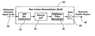
- FIG. 9A is a non-linear demodulator model for a parametric array in air
- FIG. 9B shows a graph of the damping function used for the demodulation exponent
- FIG. 10 is an AM demodulator based on a Hilbert transformer
- FIG. 11 is a single sideband channel model
- FIG. 12 is a more detailed view of the single sideband modulator in FIG. 11 ;
- FIG. 13 is a modulation side distortion compensator
- FIG. 14 is a first order baseband distortion compensator
- FIG. 15 is a Nth order audio distortion compensator
- FIG. 16 shows a Nth order audio distortion compensator as a cascade of distortion models
- FIG. 17 is a SSB channel model implemented as the magnitude squared of the Hilbert transformed input
- FIG. 18 is an AM channel model using an AM modulator.
- This invention is a signal processing apparatus and method, implemented either digitally or in analog, which significantly reduces the audible distortion of a parametric array in air.
- multiple signal processing steps are performed.
- the input side of the processor(s) accepts a line-level signal from an audio source such as a CD player.
- an analog audio signal will first be digitized or a direct digital input may be received.
- the first step in the invention multiplies the incoming audio signal by a higher ultrasonic carrier frequency to create a modulated signal.
- the carrier frequency is modulated by the incoming audio signal to generate a conventional single sideband (SSB) or double sideband (DSB) signal.
- the carrier signal is generated by a local oscillator set at the desired frequency.
- a multi-channel system stereo, for example
- This modulation may produce either a single-sideband (upper sidebands only) (SSB) multiplied with a carrier signal, or a double sideband (DSB) multiplied with a carrier signal.
- SSB single-sideband
- DSB double sideband
- a truncated double sideband (TDSB) signal may also be produced in the invention, where the lower sidebands of a double sideband (DSB) signal are sharply truncated by a filter so nearly all of the frequencies passed are above the carrier.
- the calculated envelope of the modulated signal is compared to the calculated “ideal” audio signal with the square root applied.
- This comparison uses the modulated carrier envelope to compare against the ideal audio signal with the square root applied.
- the ideal signal is the unmodulated audio signal after it has been offset by a positive DC (direct current) voltage equal in magnitude but opposite to its maximum negative peak value and then square rooted.
- a positive DC (direct current) voltage equal in magnitude but opposite to its maximum negative peak value and then square rooted.
- the frequency response of the ultrasonic transducer to be used is also taken into account in the comparison. In other words, a correction is also added which accounts for the distortion created by the transducer (i.e. speaker) when it emits the ultrasonic signals.
- the modulated signal's bandwidth or spectrum is multiplied by the actual frequency response curve of the transducer/amplifier combination. This ensures that the comparison between the ideal envelope and the modulated signal envelope is valid because the modulated signal envelope will be altered by the transducer/amplifier when it is emitted.
- TDSB truncated double side band
- the modulation scheme itself may also truncate the TDSB before it reaches the transducer. This makes it possible to use a simple DSB multiplier unit to generate a conventional DSB signal and a filter and the transducer to convert the DSB signal into a TDSB signal.
- the modulated signal envelope is then compared or subtracted from the ideal square rooted signal. This gives a new signal that represents the error. This new signal is then inverted (in phase or in sign) and summed with the original incoming audio signal just ahead of the modulation step. This serves to alter the resulting envelope so that it is a closer match to the ideal envelope.
- a significant feature of the present invention is the error terms that are calculated and then added back into the audio signal are always within the audio bandwidth of the original audio signal and no extra bandwidth is required.
- the primary distortion correction occurs within the audio signal but some of the distortion correction terms may be outside of the audio signal if the added terms do not produce significant distortion.
- the error correction is preferably done recursively a number of times until the SSB, DSB or TDSB envelope error versus the ideal signal is within a desired small amount. The number of recursive steps will depend on the desired amount of distortion reduction and on the practical limits of the processor.
- the modulated signal is then output to an amplifier and ultimately to the ultrasonic transducer where it is emitted into the air or some other medium.
- the ultrasonic waves then demodulate into the original audio signal according to Berktay's solution.
- Each recursive step reduces the total harmonic distortion (THD) error percentage by at least one-half, with the actual amount depending on the incoming spectrum and the modulation method chosen.
- the number of recursive steps is dependent upon the processing power available and the desired level of correction. Generally, a half-dozen iterations or less of the recursion process produces the desired distortion correction.
- the processing power required for this level of correction in real-time is low and could be implemented on an inexpensive DSP chip, or equivalent hardware.
- a carrier modulated by a square rooted audio signal has infinite bandwidth and cannot be emitted accurately by any known means. Using this method makes it possible to approximate the ideal envelope without requiring the substantially increased bandwidth that is otherwise required. It should be recognized that error correction could be performed with only one level of error correction if desired.
- Analog circuitry could also be used instead of a digital or software implementation of the invention.
- the modulated signal which is an ultrasonic frequency would usually be converted back into analog form before amplification.
- a high sampling rate is needed for a faithful digital to analog conversion in the output stage.
- the output signal would have a spectrum from 35 kHz to 55 kHz.
- a sampling rate of 96 kHz or higher would be a good choice.
- the standard 44.1 kHz tends to be insufficient for wideband audio. In contrast, certain applications for speech could use lower sampling rates.
- the output signal for the digital implementation is at line level. This signal would be input to an ultrasonic amplifier which would in turn drive the transducer.
- the demodulated signal is proportional to the square of the modulation envelope.
- the demodulated audio begins to be proportional to the envelope itself, not its square. This can be taken into account in the error correction compensator if the final drive level is known. For example, if the amplifier and the signal processor were integrated, the error correction scheme could vary with the power output in relation to the amplifier settings. Varying the error correction with the power output is described in more detail later. For simpler systems, the square of the envelope can be used as the demodulation model with good results.
- the carrier frequency and modulated signal frequencies can be lowered without worrying about the lower sidebands which would otherwise be emitted in the audible range (i.e. audible distortion).
- the carrier frequency and modulated signal frequencies can be lowered so they are close to the upper limit of the audible range.
- close is defined, as close to the upper limit of the audible range as possible without producing significant distortion and where the carrier signal and sidebands are inaudible.
- a lower carrier frequency allows for better conversion efficiency in three ways.
- SPL sound pressure level
- the amplitude of the audio signal generated is proportional to the square of the ultrasonic SPL. In other words, the gain of the system increases with increasing drive levels, until the saturation limit is reached. The saturation limit is increased by lowering the carrier frequency.
- Third, a lower carrier frequency increases the volume velocity available to the system and therefore increases the available output in the audible range.
- the single sideband (SSB) method is used to specifically decrease the carrier frequency as far as possible which maximizes the efficiency of the ultrasonic-to-audio conversion.
- SSB single sideband
- With a lower frequency saturation carrier higher saturation levels can be achieved because the acoustic saturation limit is higher with longer acoustic wavelengths.
- the ideal envelope can be created using only the upper sidebands of a carrier modulated by an audio signal.
- FIG. 6 shows the reproduction of simultaneous 5 kHz and 6 kHz tones. This SSB spectra would normally look like what is shown in FIG. 6 .
- the ideal envelope shape with the square root applied is shown in FIG. 7 which is the waveform that would result from the SSB spectrum in FIG. 6 . It is important to note that the amplitude of the SSB signal does not always match the desired envelope shape. However, if another upper sideband component is artificially inserted, a much better fit can be achieved.
- the new frequency component in this case is 41 kHz. Adding in additional frequencies is a very simplified version of the error correction that was described above.
- the new sideband frequency is equal to the carrier plus the difference between the two upper sidebands.
- the carrier is 40 kHz and the dominant sideband frequencies are 5 kHz and 6 kHz so the artificial sideband is 41 kHz, and no extra bandwidth is required when inserting this new component.
- the two frequencies with dominant magnitudes can always be used to determine the location of the new sideband.
- SSB or TDSB scheme is advantageous because it more ideally matches the amplitude output of a typical ultrasonic transducer above and below its resonant frequency.
- the carrier in an SSB or TDSB arrangement would be placed at the fundamental resonant frequency of the transducer for maximum speaker output levels, and the upper sideband frequencies would fall on the upper side of the resonant peak where the transducer operates efficiently.
- Many transducers work well above the resonance frequency, and poorly below this peak frequency.
- a distortion compensator is positioned after the modulator to cancel first-order distortion products.
- a first order base-band compensator is used which can also be recursively extended to an Nth order distortion compensator.
- the base-band compensators pre-distort the audio signal prior to modulation.
- the first order distortion correction is applied it creates smaller distortion terms which are then corrected in the next level of recursion.
- Significant distortion improvements have been shown using the Nth order compensator with various modulation schemes.
- the first component of the invention models the non-linear demodulation which occurs in the air column of a parametric speaker. This relationship must be modeled to provide a proper approximation of the distortion which is needed to produce the correct acoustic sound wave.
- the second derivative function in Berktay's solution presents a linear distortion that may be compensated for by passing the audio signal through a double integrator prior to subsequent processing and modulation. Since the focus here is to control the non-linear distortion component, the derivative which can be handled by simple equalization techniques will be dropped from this discussion.
- FIG. 9A shows a block diagram representation of a non-linear demodulator which does not model the second derivative.
- Ultrasonic acoustic waves 30 are emitted into the air which performs a demodulation function modeled by the AM demodulator 32 . Since an audio signal can't contain a DC term, a high-pass filter 30 has been added to the model to remove the DC component from the output of the squarer block 32 . A gain constant, ⁇ is included at 38 for scaling purposes and an acoustic audio output is then generated 40 .
- the air column demodulator in the figure is referred to as the non-linear demodulator or NLD.
- the squaring function in the non-linear demodulator uses an exponent which decreases as the intensity of the ultrasonic signal increases.
- the demodulation exponent of this invention can increase from 1 ⁇ 2 to 1 in a smooth curved fashion or it can be linearly interpolated from 1 ⁇ 2 to 1. Increasing the exponent, models the air saturation that takes place as the power of the ultrasonic signal increases.
- FIG. 9B shows the damping function of the demodulation exponent with respect to the intensity in decibels of the ultrasonic signals. It should be realized based on this disclosure that applying a damping function is similar to pre-processing the signal by applying the square root at lower signal power and then increasing the square root function to 1 as the power of the signal and saturation increase. This function which interpolates the square root up to one can be modeled as either a linear function, quadratic (n 2 ) function or a cubic (n 3 ) function.
- FIG. 10 expands the AM demodulator block of FIG. 9A with the ideal instantaneous AM demodulator based on the Hilbert transformer.
- An ultrasonic signal is received at the input 42 and passed to the Hilbert transformer 46 .
- the Hilbert transformer 46 is a linear filter that simply shifts the phase of any input tone by 90 degrees without affecting its amplitude. For example, an input of b cos( ⁇ t) is transformed to an output of b sin( ⁇ t).
- the magnitude block 48 computes the square root of the sum of the squares of the real and imaginary inputs, thus extracting the signal's instantaneous amplitude which provides a demodulated output 50 .
- SSB channel model 60 which models an uncompensated parametric array system that uses a SSB modulator 70 .
- a single sideband (SSB) channel model 60 is constructed by adding a SSB modulator 70 and the ultrasonic transducer response 64 in front of the non-linear air column demodulator (NLD) 66 .
- An audio input 62 enters the SSB channel model and an acoustic audio output 69 model is produced.
- the ultrasonic transducer 64 i.e. speaker
- h(t) is typically bandpass in nature.
- the NLD details are given in the description of FIG. 9A .
- the SSB modulator 70 is expanded in FIG. 12 and specifically performs upper sideband modulation with carrier feed-through. It is assumed that there is no DC term present in the modulator input 72 .
- the modulator input 72 is received and the Hilbert transformer 74 is used to derive the complex analytic signal having real RE and imaginary parts IM prior to the summing node 76 . Unlike a real signal, with its negative frequency components equal to the conjugate of its positive frequencies, it can be shown that the analytic signal has no negative frequency components.
- the modulator 78 modulates the analytic signal with e j ⁇ 0 t , and right shifts its spectrum by ⁇ 0 .
- the constant, 1 is added to the signal path in the summing node 76 to cause some carrier signal to pass through.
- Taking the real part 80 restores the negative frequency components of the signal.
- the single sideband modulator shifts the audio spectrum right by ⁇ 0 and adds a carrier tone at ⁇ 0 .
- the distortion of a SSB modulator with discrete tone input signals can be reduced by this invention.
- the distortion products have frequencies that are equal to the differences of the primary input signals.
- the distortion tones have a lower amplitude than the primary input tones if the modulation index is less than one (amplitude of the carrier signal is greater than the peak modulated signal amplitude). So, if additional input tones are injected at the distortion frequencies it completely cancels these “first-order” distortion products. The result is that “second-order” distortion products are introduced at the additional tone difference frequencies.
- the amplitude of the secondary distortion products is significantly less than the original distortion amplitude, resulting in an overall improvement of distortion figures.
- Application of additional canceling tones in a recursive manner further improves output distortion.
- Distortion-tone injection works by observing the amplitude of the distortion and injecting a tone with the same amplitude and opposite phase. This works because the SSB channel model passes input tones without significant amplitude or phase modification, and superposition (summation) applies at the acoustic output facilitating the cancellation. This assumes a unity gain transducer model.
- This invention uses a modulation-side distortion compensator, shown in FIG. 13 , that predicts, then cancels the first-order distortion components after the SSB modulator.
- the distortion component can be estimated as shown in FIG. 13 . Assume initially that h(t) is unity or 1.
- This compensator also works for the case the h(t) is approximately unity.
- the system may be modified to handle an arbitrary transducer response by including a transducer inverse model. This is not detailed here because the base-band distortion compensator discussed below is the most preferred embodiment.
- Another method of distortion abatement is to subtract the distortion products from the main modulator input as detailed in FIG. 14 .
- This is known in the invention as a first-order distortion compensator.
- the transducer response, h(t) is ignored in the SSB channel model 110 because its inverse is applied prior to the actual transducer.
- the cascade of h ⁇ 1 (t) and h(t) is approximately unity (at least over the frequency range of interest) so tout(t) ⁇ mod(t).
- the audio distortion is estimated using the SSB Channel Model. A portion of the estimated distortion signal is subtracted from the audio signal, thus reducing distortion in the acoustic output.
- the SSB channel model 110 is used to derive an estimate of the first order distortion products dist(t).
- the distortion is estimated by using the SSB Channel model 110 to estimate the distortion 114 , and then the original audio input 112 is subtracted from the estimated distorted signal 114 leaving the distortion dist(t), 118 .
- This distortion is scaled by the parameter c, (0 ⁇ c ⁇ 1), 120 and subtracted 122 from the original audio input 112 , resulting in the first-order pre-distorted audio signal, x 1 (t) at 124 .
- the cancellation parameter, c controls the percentage of the first-order distortion that is canceled.
- the bandwidth of the distortion, dist(t), and pre-distorted signal, x 1 (t) are also limited to 20 kHz.
- the single sideband modulator simply right shifts (translates) the spectrum of x 1 (t) and adds a carrier. Therefore, the bandwidth of mod(t) is also limited to 20 kHz (although the center frequency is high).
- the main implication of this is that the actual transducer bandwidth need only be 20 kHz wide and the inverse filter, h ⁇ 1 (t) need only perform inversion over the 20 kHz band of interest.
- One of the benefits of this system is that difficult transducer responses may be dealt with easier.
- the first-order compensator of FIG. 14 is easily extendable to higher order compensators by the recursive application of additional stages.
- the Nth order distortion compensator is shown in FIG. 15 .
- the pre-distorted signal, x 1 (t) is used as the input to another distortion compensator, and so on, until the desired order is reached.
- FIG. 15 shows that the audio distortion is recursively estimated using SSB Channel Models. A portion of the estimated distortion signal is subtracted from the pre-distorted input by each level of recursion, thus reducing distortion in the acoustic output. There is a point of diminishing returns where no further improvement is attained as the compensator recursion levels are increased, especially for a high modulation index.
- Equation 4 is depicted in FIG. 16 and shows that the Nth order distortion compensator may viewed as the cascade of distortion models subtracted from the original audio input.
- the SSB channel model may simplified which creates a more efficient implementation for the distortion compensators.
- the SSB channel model is used as part of the distortion controller, an efficient implementation is desirable.
- the SSB channel model (excluding the transducer response) is expanded in the top 150 of FIG. 17 .
- the basic principle of the Nth order recursive distortion compensator also works with an amplitude modulator.
- the channel model must be redefined to include the AM modulator as shown in FIG. 18 .
- Substituting the AM channel model into the base-band compensator results in an effective distortion control system that avoids the complexities of the single sideband modulator.
- bandwidth expansion is an issue in the AM case because an AM modulator has the property of doubling the signal's bandwidth.
- the Nth order distortion compensator of FIG. 15 is modified for the AM case by substituting in the AM channel model from FIG. 18 and the AM modulator in place of the SSB modulator.
- the ultrasonic transducer will typically cut off or attenuate a portion of the lower sideband of the AM frequency spectrum. For this reason, the filter g(t), is required in the AM channel model to simulate this attenuation. Minimum requirements for this filter is that it be linear phase filter and have a bandpass characteristic similar to the actual transducer used in the system.
- the first option is to choose h comp (t) as the approximate inverse of the transducer response h(t). This choice will flatten out the amplitude response of the cascade g(t), and linearize the phase.
- g(t) is a model of the cascade of the transducer inverse and the transducer filters as in the bottom portion of FIG. 15 . This is the preferred option because very low order (first-order) distortion controllers are effective.
- the second option is to compensate only for the phase of the transducer model with h comp (t).
- Gain variations with frequency will be present in the cascade g(t).
- a pair of equal amplitude tones may emerge at the output with different amplitudes. This amplitude error will be treated as distortion.
- the effect of the Nth order compensator will equalize the amplitude difference between the two tones and improve the distortion.
- performance suffers when compared to using phase and amplitude compensation.
- Another useful simplification is to lower the carrier frequency of the AM modulator in the AM channel model and shift down the frequency response of the filter g(t), so that it is in the correct position relative to the carrier.
- the final modulator remains at the desired carrier frequency. Only the carrier frequencies of modulators in the AM channel models are reduced. These changes preserve the input/output relationship of the AM channel model, but lower the maximum signal frequency to twice the system bandwidth (e.g. maximum frequency of 40 kHz for a 20 kHz system). This simplifies a DSP based implementation by reducing the sampling rate.
Landscapes
- Physics & Mathematics (AREA)
- Engineering & Computer Science (AREA)
- Acoustics & Sound (AREA)
- Signal Processing (AREA)
- Circuit For Audible Band Transducer (AREA)
- Transducers For Ultrasonic Waves (AREA)
Abstract
Description
p(t)∝∂2/∂t2[(env(t))2]. (Equation 1)
This is called “Berktay's far-field solution” for a parametric acoustic array. Berktay looked at the far-field because the ultrasonic signals are no longer present there (by definition). The near-field demodulation produces the same audio signals, but there is also ultrasound present which must be included in a general solution. Since the near-field ultrasound isn't audible, it can be ignored and with this assumption, Berktay's solution is valid in the near-field too.
x i+1(t)=x i(t)−c i(M(x i(t))−x o(t))0, 1, 2, . . . , N−1 (Equation 2)
where M(·) is the channel model and x0(t) is defined as the input; x0(t)=x(t). Next, define the distortion generator system, D(·) as the difference between the channel model output and its input,
D(x i(t))=M(x i(t))−x i(t) (Equation 3)
Let the cancellation parameters be unity, ci=1 for all i. Note that D(xi(t)) is the distortion or error signal generated by the non-linear plant. It is zero only when the plant is distortion free. Combining equations (2) and (3), we get an alternative expression for the pre-distorted signals,
x i+1(t)=x 0(t)−D(x i(t))i=0, 1, 2, . . . , N−1 (Equation 4)
Equation 4 is depicted in
g(t)=h comp(t)*h(t) (Equation 5)
where “*” is the convolution operator, hcomp(t) is the compensation filter, and h(t) is the transducer response.
Claims (18)
Priority Applications (1)
| Application Number | Priority Date | Filing Date | Title |
|---|---|---|---|
| US11/651,944 US7729498B2 (en) | 1999-08-26 | 2007-01-09 | Modulator processing for a parametric speaker system |
Applications Claiming Priority (3)
| Application Number | Priority Date | Filing Date | Title |
|---|---|---|---|
| US09/384,084 US6584205B1 (en) | 1999-08-26 | 1999-08-26 | Modulator processing for a parametric speaker system |
| US10/393,893 US7162042B2 (en) | 1999-08-26 | 2003-03-21 | Modulator processing for a parametric speaker system |
| US11/651,944 US7729498B2 (en) | 1999-08-26 | 2007-01-09 | Modulator processing for a parametric speaker system |
Related Parent Applications (1)
| Application Number | Title | Priority Date | Filing Date |
|---|---|---|---|
| US10/393,893 Continuation US7162042B2 (en) | 1999-08-26 | 2003-03-21 | Modulator processing for a parametric speaker system |
Publications (2)
| Publication Number | Publication Date |
|---|---|
| US20080063214A1 US20080063214A1 (en) | 2008-03-13 |
| US7729498B2 true US7729498B2 (en) | 2010-06-01 |
Family
ID=23515971
Family Applications (3)
| Application Number | Title | Priority Date | Filing Date |
|---|---|---|---|
| US09/384,084 Expired - Lifetime US6584205B1 (en) | 1999-08-26 | 1999-08-26 | Modulator processing for a parametric speaker system |
| US10/393,893 Expired - Lifetime US7162042B2 (en) | 1999-08-26 | 2003-03-21 | Modulator processing for a parametric speaker system |
| US11/651,944 Expired - Fee Related US7729498B2 (en) | 1999-08-26 | 2007-01-09 | Modulator processing for a parametric speaker system |
Family Applications Before (2)
| Application Number | Title | Priority Date | Filing Date |
|---|---|---|---|
| US09/384,084 Expired - Lifetime US6584205B1 (en) | 1999-08-26 | 1999-08-26 | Modulator processing for a parametric speaker system |
| US10/393,893 Expired - Lifetime US7162042B2 (en) | 1999-08-26 | 2003-03-21 | Modulator processing for a parametric speaker system |
Country Status (8)
| Country | Link |
|---|---|
| US (3) | US6584205B1 (en) |
| EP (1) | EP1210845A1 (en) |
| JP (1) | JP2003507982A (en) |
| CN (1) | CN1378764A (en) |
| AU (1) | AU7333000A (en) |
| CA (1) | CA2382986A1 (en) |
| HK (1) | HK1047214A1 (en) |
| WO (1) | WO2001015491A1 (en) |
Cited By (13)
| Publication number | Priority date | Publication date | Assignee | Title |
|---|---|---|---|---|
| US20110227662A1 (en) * | 2010-03-17 | 2011-09-22 | Frank Joseph Pompei | Hybrid modulation method for parametric audio system |
| KR101081877B1 (en) | 2010-04-16 | 2011-11-09 | 국방과학연구소 | Apparatus and method for transmitting and receiving a sound in air using a parametric array |
| WO2014043543A1 (en) | 2012-09-13 | 2014-03-20 | Parametric Sound Corporation | Personal audio system and method |
| US8767979B2 (en) | 2010-06-14 | 2014-07-01 | Parametric Sound Corporation | Parametric transducer system and related methods |
| US20140233760A1 (en) * | 2013-02-18 | 2014-08-21 | Panasonic Corporation | Ultrasonic speaker system |
| US8903104B2 (en) | 2013-04-16 | 2014-12-02 | Turtle Beach Corporation | Video gaming system with ultrasonic speakers |
| US8934650B1 (en) | 2012-07-03 | 2015-01-13 | Turtle Beach Corporation | Low profile parametric transducers and related methods |
| US8958580B2 (en) | 2012-04-18 | 2015-02-17 | Turtle Beach Corporation | Parametric transducers and related methods |
| US8976980B2 (en) | 2011-03-24 | 2015-03-10 | Texas Instruments Incorporated | Modulation of audio signals in a parametric speaker |
| US8988911B2 (en) | 2013-06-13 | 2015-03-24 | Turtle Beach Corporation | Self-bias emitter circuit |
| US9036831B2 (en) | 2012-01-10 | 2015-05-19 | Turtle Beach Corporation | Amplification system, carrier tracking systems and related methods for use in parametric sound systems |
| US9247342B2 (en) | 2013-05-14 | 2016-01-26 | James J. Croft, III | Loudspeaker enclosure system with signal processor for enhanced perception of low frequency output |
| US9332344B2 (en) | 2013-06-13 | 2016-05-03 | Turtle Beach Corporation | Self-bias emitter circuit |
Families Citing this family (81)
| Publication number | Priority date | Publication date | Assignee | Title |
|---|---|---|---|---|
| JP2000050387A (en) | 1998-07-16 | 2000-02-18 | Massachusetts Inst Of Technol <Mit> | Parametric audio system |
| US6850623B1 (en) * | 1999-10-29 | 2005-02-01 | American Technology Corporation | Parametric loudspeaker with improved phase characteristics |
| US7391872B2 (en) * | 1999-04-27 | 2008-06-24 | Frank Joseph Pompei | Parametric audio system |
| US6584205B1 (en) * | 1999-08-26 | 2003-06-24 | American Technology Corporation | Modulator processing for a parametric speaker system |
| US7596229B2 (en) * | 1999-08-26 | 2009-09-29 | American Technology Corporation | Parametric audio system for operation in a saturated air medium |
| US20050195985A1 (en) * | 1999-10-29 | 2005-09-08 | American Technology Corporation | Focused parametric array |
| US7062050B1 (en) * | 2000-02-28 | 2006-06-13 | Frank Joseph Pompei | Preprocessing method for nonlinear acoustic system |
| NL1014526C2 (en) | 2000-02-29 | 2001-08-30 | N2It Dev B V I O | Disc to be used in a signal processing device as well as such a device. |
| DE10151173B4 (en) * | 2001-10-17 | 2012-07-12 | Rohde & Schwarz Gmbh & Co. Kg | Method for measuring the modulation error of digitally modulated high-frequency signals |
| US6639949B2 (en) * | 2001-12-17 | 2003-10-28 | Ibiquity Digital Corporation | Method and apparatus for pulse overlap pre-compensation in digitally modulated signals |
| CA2474257A1 (en) * | 2002-01-18 | 2003-08-07 | American Technology Corporation | Modulator- amplifier |
| DE10215112C1 (en) | 2002-04-05 | 2003-09-25 | Meinig Metu System | Abutting pipe connection uses clamping device for securing annular edges of coupling flanges at ends of abutting pipe sections together |
| SG109498A1 (en) * | 2002-05-03 | 2005-03-30 | Sony Corp | Method and apparatus for generating a directional audio signal |
| AU2003265815A1 (en) * | 2002-08-26 | 2004-03-11 | Frank Joseph Pompei | Parametric array modulation and processing method |
| US20040114770A1 (en) | 2002-10-30 | 2004-06-17 | Pompei Frank Joseph | Directed acoustic sound system |
| TW586326B (en) * | 2002-12-31 | 2004-05-01 | Vistapoint Inc | Apparatus and method for generating a directional acoustic wave |
| US8849185B2 (en) | 2003-04-15 | 2014-09-30 | Ipventure, Inc. | Hybrid audio delivery system and method therefor |
| US7801570B2 (en) * | 2003-04-15 | 2010-09-21 | Ipventure, Inc. | Directional speaker for portable electronic device |
| US20060280315A1 (en) * | 2003-06-09 | 2006-12-14 | American Technology Corporation | System and method for delivering audio-visual content along a customer waiting line |
| US20050089205A1 (en) * | 2003-10-23 | 2005-04-28 | Ajay Kapur | Systems and methods for viewing an abnormality in different kinds of images |
| US7564981B2 (en) * | 2003-10-23 | 2009-07-21 | American Technology Corporation | Method of adjusting linear parameters of a parametric ultrasonic signal to reduce non-linearities in decoupled audio output waves and system including same |
| JP4181492B2 (en) * | 2003-12-25 | 2008-11-12 | 株式会社日立製作所 | Communication system for control and monitoring and modulation method setting method |
| DE102004010179A1 (en) | 2004-03-02 | 2005-10-06 | Siemens Ag | Method and data processing device for updating computer programs by data transmission |
| US7313242B2 (en) * | 2004-03-16 | 2007-12-25 | Palo Alto Research Center Incorporated | Hypersonic transducer |
| US6911925B1 (en) * | 2004-04-02 | 2005-06-28 | Tektronix, Inc. | Linearity compensation by harmonic cancellation |
| SG116545A1 (en) * | 2004-05-04 | 2005-11-28 | Sony Corp | Method and apparatus for distortion reduction in ultrasonic beam audio systems. |
| US7818175B2 (en) * | 2004-07-30 | 2010-10-19 | Dictaphone Corporation | System and method for report level confidence |
| JP4103877B2 (en) * | 2004-09-22 | 2008-06-18 | セイコーエプソン株式会社 | Electrostatic ultrasonic transducer and ultrasonic speaker |
| US20080291973A1 (en) * | 2004-11-16 | 2008-11-27 | Acco | Integrated Ultra-Wideband (Uwb) Pulse Generator |
| WO2006086743A2 (en) * | 2005-02-09 | 2006-08-17 | American Technology Corporation | In-band parametric sound generation system |
| US7694567B2 (en) * | 2005-04-11 | 2010-04-13 | Massachusetts Institute Of Technology | Acoustic detection of hidden objects and material discontinuities |
| US8032372B1 (en) * | 2005-09-13 | 2011-10-04 | Escription, Inc. | Dictation selection |
| CN1940856B (en) * | 2005-09-26 | 2010-06-23 | 鸿富锦精密工业(深圳)有限公司 | Sound output system and method |
| WO2007042850A1 (en) | 2005-10-12 | 2007-04-19 | Acco | Insulated gate field-effet transistor having a dummy gate |
| KR100622078B1 (en) * | 2005-11-21 | 2006-09-13 | 주식회사 솔리토닉스 | Superdirectional speaker system and signal processing method |
| JP2007267368A (en) * | 2006-03-03 | 2007-10-11 | Seiko Epson Corp | Speaker device, sound reproduction method, and speaker control device |
| WO2007148242A2 (en) * | 2006-06-21 | 2007-12-27 | Nxp B.V. | Method for demodulating a modulated signal, demodulator and receiver |
| US8275137B1 (en) * | 2007-03-22 | 2012-09-25 | Parametric Sound Corporation | Audio distortion correction for a parametric reproduction system |
| JP5040528B2 (en) * | 2007-08-28 | 2012-10-03 | ソニー株式会社 | Audio signal transmitting apparatus, audio signal receiving apparatus, and audio signal transmission method |
| EP2232483B1 (en) * | 2007-12-28 | 2012-02-22 | Frank Joseph Pompei | Sound field controller |
| US7863645B2 (en) * | 2008-02-13 | 2011-01-04 | ACCO Semiconductor Inc. | High breakdown voltage double-gate semiconductor device |
| US9240402B2 (en) | 2008-02-13 | 2016-01-19 | Acco Semiconductor, Inc. | Electronic circuits including a MOSFET and a dual-gate JFET |
| US7969243B2 (en) | 2009-04-22 | 2011-06-28 | Acco Semiconductor, Inc. | Electronic circuits including a MOSFET and a dual-gate JFET |
| US8928410B2 (en) | 2008-02-13 | 2015-01-06 | Acco Semiconductor, Inc. | Electronic circuits including a MOSFET and a dual-gate JFET |
| JP2009080511A (en) * | 2009-01-22 | 2009-04-16 | Clarion Co Ltd | Impulse response measuring device and impulse response measuring method |
| US7808415B1 (en) * | 2009-03-25 | 2010-10-05 | Acco Semiconductor, Inc. | Sigma-delta modulator including truncation and applications thereof |
| JP2010232714A (en) * | 2009-03-25 | 2010-10-14 | Advantest Corp | Signal processing apparatus, digital filter, and program |
| KR20120054082A (en) | 2009-08-25 | 2012-05-29 | 난양 테크놀러지컬 유니버시티 | A directional sound system |
| US7952431B2 (en) * | 2009-08-28 | 2011-05-31 | Acco Semiconductor, Inc. | Linearization circuits and methods for power amplification |
| US8532584B2 (en) | 2010-04-30 | 2013-09-10 | Acco Semiconductor, Inc. | RF switches |
| BR112013001418A2 (en) | 2010-07-22 | 2016-05-24 | Koninkl Philips Electronics Nv | "directional signal generating apparatus for parametric speakers, parametric speaker system and parametric speaker routing method" |
| JP5859648B2 (en) | 2011-08-16 | 2016-02-10 | エンパイア テクノロジー ディベロップメント エルエルシー | Technology for generating audio signals |
| KR20140006386A (en) * | 2012-07-05 | 2014-01-16 | 한국전자통신연구원 | Methods and apparatus for transmitting sound wave in water |
| CN104620601A (en) * | 2012-09-14 | 2015-05-13 | Nec卡西欧移动通信株式会社 | Speaker device and electronic equipment |
| US9474265B2 (en) | 2012-11-27 | 2016-10-25 | Elwha Llc | Methods and systems for directing birds away from equipment |
| US9775337B2 (en) | 2012-11-27 | 2017-10-03 | Elwha Llc | Methods and systems for directing birds away from equipment |
| US10575093B2 (en) | 2013-03-15 | 2020-02-25 | Elwha Llc | Portable electronic device directed audio emitter arrangement system and method |
| US9886941B2 (en) | 2013-03-15 | 2018-02-06 | Elwha Llc | Portable electronic device directed audio targeted user system and method |
| US10291983B2 (en) | 2013-03-15 | 2019-05-14 | Elwha Llc | Portable electronic device directed audio system and method |
| US10531190B2 (en) | 2013-03-15 | 2020-01-07 | Elwha Llc | Portable electronic device directed audio system and method |
| US10181314B2 (en) | 2013-03-15 | 2019-01-15 | Elwha Llc | Portable electronic device directed audio targeted multiple user system and method |
| JP6213916B2 (en) * | 2013-09-27 | 2017-10-18 | 国立大学法人九州工業大学 | Directional sound system |
| US10271146B2 (en) | 2014-02-08 | 2019-04-23 | Empire Technology Development Llc | MEMS dual comb drive |
| US9913048B2 (en) | 2014-02-08 | 2018-03-06 | Empire Technology Development Llc | MEMS-based audio speaker system with modulation element |
| US10123126B2 (en) * | 2014-02-08 | 2018-11-06 | Empire Technology Development Llc | MEMS-based audio speaker system using single sideband modulation |
| WO2015119626A1 (en) | 2014-02-08 | 2015-08-13 | Empire Technology Development Llc | Mems-based structure for pico speaker |
| US9432785B2 (en) * | 2014-12-10 | 2016-08-30 | Turtle Beach Corporation | Error correction for ultrasonic audio systems |
| TWI563497B (en) * | 2015-03-31 | 2016-12-21 | Merry Electronics Co Ltd | Recovery method and device for close range acoustic wave |
| US10134416B2 (en) | 2015-05-11 | 2018-11-20 | Microsoft Technology Licensing, Llc | Privacy-preserving energy-efficient speakers for personal sound |
| US9848262B2 (en) * | 2016-03-23 | 2017-12-19 | Harman International Industries, Incorporated | Techniques for tuning the distortion response of a loudspeaker |
| US9923741B2 (en) * | 2016-03-24 | 2018-03-20 | The United States Of America As Represented By Secretary Of The Navy | Method for detecting presence or absence of phase shift keying modulations |
| US10403082B2 (en) * | 2016-04-12 | 2019-09-03 | Igt Canada Solutions Ulc | Systems and methods for providing private sound from a wagering gaming machine via modulated ultrasound |
| CN107708041A (en) * | 2017-09-02 | 2018-02-16 | 上海朗宴智能科技有限公司 | A kind of audio beam loudspeaker |
| CN108305638B (en) * | 2018-01-10 | 2020-07-28 | 维沃移动通信有限公司 | Signal processing method, signal processing device and terminal equipment |
| CN111213422A (en) * | 2018-02-14 | 2020-05-29 | Oppo广东移动通信有限公司 | Indication method, detection method and related equipment |
| CN108600915B (en) * | 2018-08-09 | 2024-02-06 | 歌尔科技有限公司 | Audio output method and device, harmonic distortion filtering equipment and terminal |
| FR3087609B1 (en) * | 2018-10-17 | 2020-11-13 | Akoustic Arts | PRECORRECTION PROCESS OF A SOUND SIGNAL, SOUND GENERATION PROCESS, ASSOCIATED PROCESSING UNIT AND LOUDSPEAKER |
| US10986447B2 (en) | 2019-06-21 | 2021-04-20 | Analog Devices, Inc. | Doppler compensation in coaxial and offset speakers |
| US11246001B2 (en) | 2020-04-23 | 2022-02-08 | Thx Ltd. | Acoustic crosstalk cancellation and virtual speakers techniques |
| CN113781991A (en) * | 2021-08-20 | 2021-12-10 | 苏州三星电子电脑有限公司 | Noise reduction device, noise reduction method and multimedia equipment |
| CN119781327B (en) * | 2024-09-30 | 2026-03-20 | 比亚迪股份有限公司 | Signal processing methods, apparatus, devices, systems, storage media, and program products |
Citations (15)
| Publication number | Priority date | Publication date | Assignee | Title |
|---|---|---|---|---|
| US3825834A (en) | 1972-07-05 | 1974-07-23 | Rixon Eleronics Inc | Digital ssb transmitter |
| US4149031A (en) | 1976-06-30 | 1979-04-10 | Cooper Duane H | Multichannel matrix logic and encoding systems |
| US4418404A (en) | 1981-10-01 | 1983-11-29 | The United States Of America As Represented By The Secretary Of The Navy | Single-sideband acoustic telemetry |
| US4503553A (en) | 1983-06-03 | 1985-03-05 | Dbx, Inc. | Loudspeaker system |
| US4823908A (en) | 1984-08-28 | 1989-04-25 | Matsushita Electric Industrial Co., Ltd. | Directional loudspeaker system |
| US4991687A (en) | 1989-03-14 | 1991-02-12 | Pioneer Electronic Corporation | Speaker system having directivity |
| US5109416A (en) | 1990-09-28 | 1992-04-28 | Croft James J | Dipole speaker for producing ambience sound |
| US5357578A (en) | 1992-11-24 | 1994-10-18 | Canon Kabushiki Kaisha | Acoustic output device, and electronic apparatus using the acoustic output device |
| US5406634A (en) | 1993-03-16 | 1995-04-11 | Peak Audio, Inc. | Intelligent speaker unit for speaker system network |
| US5572201A (en) * | 1994-08-05 | 1996-11-05 | Federal Signal Corporation | Alerting device and system for abnormal situations |
| US5582176A (en) | 1995-08-15 | 1996-12-10 | Medasonics | Methods and apparatus for automatically determining edge frequency in doppler ultrasound signals |
| US5859915A (en) | 1997-04-30 | 1999-01-12 | American Technology Corporation | Lighted enhanced bullhorn |
| US5889870A (en) | 1996-07-17 | 1999-03-30 | American Technology Corporation | Acoustic heterodyne device and method |
| US6584205B1 (en) * | 1999-08-26 | 2003-06-24 | American Technology Corporation | Modulator processing for a parametric speaker system |
| US6606389B1 (en) | 1997-03-17 | 2003-08-12 | American Technology Corporation | Piezoelectric film sonic emitter |
Family Cites Families (5)
| Publication number | Priority date | Publication date | Assignee | Title |
|---|---|---|---|---|
| JPS62296698A (en) * | 1986-06-17 | 1987-12-23 | Matsushita Electric Ind Co Ltd | Parametric speaker |
| JPH0779516B2 (en) * | 1986-11-04 | 1995-08-23 | 松下電器産業株式会社 | Parametric speaker |
| DE19739425A1 (en) * | 1997-09-09 | 1999-03-11 | Bosch Gmbh Robert | Method and arrangement for reproducing a sterophonic audio signal |
| JP2000050387A (en) * | 1998-07-16 | 2000-02-18 | Massachusetts Inst Of Technol <Mit> | Parametric audio system |
| JP2000209691A (en) * | 1999-01-12 | 2000-07-28 | Mk Seiko Co Ltd | Parametric speaker |
-
1999
- 1999-08-26 US US09/384,084 patent/US6584205B1/en not_active Expired - Lifetime
-
2000
- 2000-08-25 AU AU73330/00A patent/AU7333000A/en not_active Abandoned
- 2000-08-25 EP EP00961369A patent/EP1210845A1/en not_active Withdrawn
- 2000-08-25 HK HK02108695.9A patent/HK1047214A1/en unknown
- 2000-08-25 JP JP2001519082A patent/JP2003507982A/en active Pending
- 2000-08-25 CN CN00814170A patent/CN1378764A/en active Pending
- 2000-08-25 WO PCT/US2000/023392 patent/WO2001015491A1/en not_active Ceased
- 2000-08-25 CA CA002382986A patent/CA2382986A1/en not_active Abandoned
-
2003
- 2003-03-21 US US10/393,893 patent/US7162042B2/en not_active Expired - Lifetime
-
2007
- 2007-01-09 US US11/651,944 patent/US7729498B2/en not_active Expired - Fee Related
Patent Citations (16)
| Publication number | Priority date | Publication date | Assignee | Title |
|---|---|---|---|---|
| US3825834A (en) | 1972-07-05 | 1974-07-23 | Rixon Eleronics Inc | Digital ssb transmitter |
| US4149031A (en) | 1976-06-30 | 1979-04-10 | Cooper Duane H | Multichannel matrix logic and encoding systems |
| US4418404A (en) | 1981-10-01 | 1983-11-29 | The United States Of America As Represented By The Secretary Of The Navy | Single-sideband acoustic telemetry |
| US4503553A (en) | 1983-06-03 | 1985-03-05 | Dbx, Inc. | Loudspeaker system |
| US4823908A (en) | 1984-08-28 | 1989-04-25 | Matsushita Electric Industrial Co., Ltd. | Directional loudspeaker system |
| US4991687A (en) | 1989-03-14 | 1991-02-12 | Pioneer Electronic Corporation | Speaker system having directivity |
| US5109416A (en) | 1990-09-28 | 1992-04-28 | Croft James J | Dipole speaker for producing ambience sound |
| US5357578A (en) | 1992-11-24 | 1994-10-18 | Canon Kabushiki Kaisha | Acoustic output device, and electronic apparatus using the acoustic output device |
| US5406634A (en) | 1993-03-16 | 1995-04-11 | Peak Audio, Inc. | Intelligent speaker unit for speaker system network |
| US5572201A (en) * | 1994-08-05 | 1996-11-05 | Federal Signal Corporation | Alerting device and system for abnormal situations |
| US5582176A (en) | 1995-08-15 | 1996-12-10 | Medasonics | Methods and apparatus for automatically determining edge frequency in doppler ultrasound signals |
| US5889870A (en) | 1996-07-17 | 1999-03-30 | American Technology Corporation | Acoustic heterodyne device and method |
| US6606389B1 (en) | 1997-03-17 | 2003-08-12 | American Technology Corporation | Piezoelectric film sonic emitter |
| US5859915A (en) | 1997-04-30 | 1999-01-12 | American Technology Corporation | Lighted enhanced bullhorn |
| US6584205B1 (en) * | 1999-08-26 | 2003-06-24 | American Technology Corporation | Modulator processing for a parametric speaker system |
| US7162042B2 (en) * | 1999-08-26 | 2007-01-09 | American Technology Corporation | Modulator processing for a parametric speaker system |
Non-Patent Citations (11)
Cited By (18)
| Publication number | Priority date | Publication date | Assignee | Title |
|---|---|---|---|---|
| US8866559B2 (en) * | 2010-03-17 | 2014-10-21 | Frank Joseph Pompei | Hybrid modulation method for parametric audio system |
| US20110227662A1 (en) * | 2010-03-17 | 2011-09-22 | Frank Joseph Pompei | Hybrid modulation method for parametric audio system |
| KR101081877B1 (en) | 2010-04-16 | 2011-11-09 | 국방과학연구소 | Apparatus and method for transmitting and receiving a sound in air using a parametric array |
| US8767979B2 (en) | 2010-06-14 | 2014-07-01 | Parametric Sound Corporation | Parametric transducer system and related methods |
| US9002032B2 (en) | 2010-06-14 | 2015-04-07 | Turtle Beach Corporation | Parametric signal processing systems and methods |
| US8903116B2 (en) | 2010-06-14 | 2014-12-02 | Turtle Beach Corporation | Parametric transducers and related methods |
| US8976980B2 (en) | 2011-03-24 | 2015-03-10 | Texas Instruments Incorporated | Modulation of audio signals in a parametric speaker |
| US9036831B2 (en) | 2012-01-10 | 2015-05-19 | Turtle Beach Corporation | Amplification system, carrier tracking systems and related methods for use in parametric sound systems |
| US8958580B2 (en) | 2012-04-18 | 2015-02-17 | Turtle Beach Corporation | Parametric transducers and related methods |
| US8934650B1 (en) | 2012-07-03 | 2015-01-13 | Turtle Beach Corporation | Low profile parametric transducers and related methods |
| WO2014043543A1 (en) | 2012-09-13 | 2014-03-20 | Parametric Sound Corporation | Personal audio system and method |
| US20140233760A1 (en) * | 2013-02-18 | 2014-08-21 | Panasonic Corporation | Ultrasonic speaker system |
| US8855333B2 (en) * | 2013-02-18 | 2014-10-07 | Panasonic Corporation | Ultrasonic speaker system |
| US8903104B2 (en) | 2013-04-16 | 2014-12-02 | Turtle Beach Corporation | Video gaming system with ultrasonic speakers |
| US9247342B2 (en) | 2013-05-14 | 2016-01-26 | James J. Croft, III | Loudspeaker enclosure system with signal processor for enhanced perception of low frequency output |
| US10090819B2 (en) | 2013-05-14 | 2018-10-02 | James J. Croft, III | Signal processor for loudspeaker systems for enhanced perception of lower frequency output |
| US8988911B2 (en) | 2013-06-13 | 2015-03-24 | Turtle Beach Corporation | Self-bias emitter circuit |
| US9332344B2 (en) | 2013-06-13 | 2016-05-03 | Turtle Beach Corporation | Self-bias emitter circuit |
Also Published As
| Publication number | Publication date |
|---|---|
| US20030185405A1 (en) | 2003-10-02 |
| HK1047214A1 (en) | 2003-02-07 |
| US20080063214A1 (en) | 2008-03-13 |
| US7162042B2 (en) | 2007-01-09 |
| CN1378764A (en) | 2002-11-06 |
| US6584205B1 (en) | 2003-06-24 |
| CA2382986A1 (en) | 2001-03-01 |
| WO2001015491A9 (en) | 2002-09-06 |
| EP1210845A1 (en) | 2002-06-05 |
| AU7333000A (en) | 2001-03-19 |
| JP2003507982A (en) | 2003-02-25 |
| WO2001015491A1 (en) | 2001-03-01 |
Similar Documents
| Publication | Publication Date | Title |
|---|---|---|
| US7729498B2 (en) | Modulator processing for a parametric speaker system | |
| US7224808B2 (en) | Dynamic carrier system for parametric arrays | |
| RU2569914C2 (en) | Driving parametric loudspeakers | |
| US7146011B2 (en) | Steering of directional sound beams | |
| EP1791390B1 (en) | Ultra directional speaker system and signal processing method thereof | |
| US7773761B2 (en) | Method and apparatus to generate an audio beam with high quality | |
| US20120148053A1 (en) | Directional sound system | |
| US7596228B2 (en) | Parametric array modulation and processing method | |
| US20020111795A1 (en) | System for playback of pre-encoded signals through a parametric loudspeaker system | |
| US9681225B2 (en) | Modulation systems and methods for parametric loudspeaker systems | |
| US7062050B1 (en) | Preprocessing method for nonlinear acoustic system | |
| US4995113A (en) | Device for processing an audio-frequency electrical signal | |
| Geng et al. | Virtual bass enhancement based on harmonics control using missing fundamental in parametric array loudspeaker | |
| US8866559B2 (en) | Hybrid modulation method for parametric audio system | |
| Ji et al. | Theoretical and experimental comparison of amplitude modulation techniques for parametric loudspeakers |
Legal Events
| Date | Code | Title | Description |
|---|---|---|---|
| AS | Assignment |
Owner name: AMERICAN TECHNOLOGY CORPORATION, CALIFORNIA Free format text: ASSIGNMENT OF ASSIGNORS INTEREST;ASSIGNORS:SPENCER, MICHAEL E.;CROFT, III, JAMES J.;NORRIS, JOSEPH O.;REEL/FRAME:018790/0745;SIGNING DATES FROM 20030306 TO 20030313 Owner name: AMERICAN TECHNOLOGY CORPORATION,CALIFORNIA Free format text: ASSIGNMENT OF ASSIGNORS INTEREST;ASSIGNORS:SPENCER, MICHAEL E.;CROFT, III, JAMES J.;NORRIS, JOSEPH O.;SIGNING DATES FROM 20030306 TO 20030313;REEL/FRAME:018790/0745 |
|
| STCF | Information on status: patent grant |
Free format text: PATENTED CASE |
|
| AS | Assignment |
Owner name: PARAMETRIC SOUND CORPORATION, NEVADA Free format text: ASSIGNMENT OF ASSIGNORS INTEREST;ASSIGNOR:LRAD CORPORATION;REEL/FRAME:025466/0748 Effective date: 20101013 Owner name: LRAD CORPORATION, CALIFORNIA Free format text: CHANGE OF NAME;ASSIGNOR:AMERICAN TECHNOLOGY CORPORATION;REEL/FRAME:025466/0409 Effective date: 20100324 |
|
| FPAY | Fee payment |
Year of fee payment: 4 |
|
| AS | Assignment |
Owner name: PNC BANK, NATIONAL ASSOCIATION, PENNSYLVANIA Free format text: SECURITY INTEREST IN U.S. PATENTS AND TRADEMARKS;ASSIGNOR:PARAMETRIC SOUND CORPORATION;REEL/FRAME:032032/0328 Effective date: 20140115 |
|
| AS | Assignment |
Owner name: BANK OF AMERICA, N.A., AS AGENT, CALIFORNIA Free format text: MEMORANDUM AND NOTICE OF SECURITY INTEREST IN INTELLECTUAL PROPERTY;ASSIGNOR:PARAMETRIC SOUND CORPORATION;REEL/FRAME:032608/0143 Effective date: 20140331 Owner name: PARAMETRIC SOUND CORPORATION, NEW YORK Free format text: TERMINATION AND RELEASE OF IP SECURITY AGREEMENT;ASSIGNOR:PNC BANK, NATIONAL ASSOCIATION, AS AGENT;REEL/FRAME:032608/0156 Effective date: 20140331 |
|
| AS | Assignment |
Owner name: TURTLE BEACH CORPORATION, CALIFORNIA Free format text: CHANGE OF NAME;ASSIGNOR:PARAMETRIC SOUND CORPORATION;REEL/FRAME:033917/0789 Effective date: 20140520 |
|
| AS | Assignment |
Owner name: CRYSTAL FINANCIAL LLC, AS AGENT, MASSACHUSETTS Free format text: SECURITY INTEREST;ASSIGNOR:TURTLE BEACH CORPORATION;REEL/FRAME:036159/0952 Effective date: 20150722 |
|
| AS | Assignment |
Owner name: BANK OF AMERICA, N.A., AS AGENT, CALIFORNIA Free format text: SECURITY INTEREST;ASSIGNORS:TURTLE BEACH CORPORATION;VOYETRA TURTLE BEACH, INC.;REEL/FRAME:036189/0326 Effective date: 20150722 |
|
| MAFP | Maintenance fee payment |
Free format text: PAYMENT OF MAINTENANCE FEE, 8TH YR, SMALL ENTITY (ORIGINAL EVENT CODE: M2552) Year of fee payment: 8 |
|
| AS | Assignment |
Owner name: CRYSTAL FINANCIAL LLC, AS AGENT, MASSACHUSETTS Free format text: SECURITY INTEREST;ASSIGNOR:TURTLE BEACH CORPORATION;REEL/FRAME:045573/0722 Effective date: 20180305 |
|
| AS | Assignment |
Owner name: BANK OF AMERICA, N.A., AS AGENT, CALIFORNIA Free format text: SECURITY INTEREST;ASSIGNORS:TURTLE BEACH CORPORATION;VOYETRA TURTLE BEACH, INC.;REEL/FRAME:045776/0648 Effective date: 20180305 |
|
| AS | Assignment |
Owner name: TURTLE BEACH CORPORATION, CALIFORNIA Free format text: TERMINATION AND RELEASE OF INTELLECTUAL PROPERTY SECURITY AGREEMENTS;ASSIGNOR:CRYSTAL FINANCIAL LLC;REEL/FRAME:048965/0001 Effective date: 20181217 Owner name: TURTLE BEACH CORPORATION, CALIFORNIA Free format text: TERMINATION AND RELEASE OF INTELLECTUAL PROPERTY SECURITY AGREEMENTS;ASSIGNOR:CRYSTAL FINANCIAL LLC;REEL/FRAME:047954/0007 Effective date: 20181217 |
|
| FEPP | Fee payment procedure |
Free format text: MAINTENANCE FEE REMINDER MAILED (ORIGINAL EVENT CODE: REM.); ENTITY STATUS OF PATENT OWNER: SMALL ENTITY |
|
| LAPS | Lapse for failure to pay maintenance fees |
Free format text: PATENT EXPIRED FOR FAILURE TO PAY MAINTENANCE FEES (ORIGINAL EVENT CODE: EXP.); ENTITY STATUS OF PATENT OWNER: SMALL ENTITY |
|
| STCH | Information on status: patent discontinuation |
Free format text: PATENT EXPIRED DUE TO NONPAYMENT OF MAINTENANCE FEES UNDER 37 CFR 1.362 |
|
| FP | Lapsed due to failure to pay maintenance fee |
Effective date: 20220601 |
|
| AS | Assignment |
Owner name: TURTLE BEACH CORPORATION, CALIFORNIA Free format text: RELEASE BY SECURED PARTY;ASSIGNOR:BANK OF AMERICA, N.A.;REEL/FRAME:072470/0260 Effective date: 20250801 Owner name: VOYETRA TURTLE BEACH, INC., CALIFORNIA Free format text: RELEASE BY SECURED PARTY;ASSIGNOR:BANK OF AMERICA, N.A.;REEL/FRAME:072470/0260 Effective date: 20250801 Owner name: PERFORMANCE DESIGNED PRODUCTS LLC, CALIFORNIA Free format text: RELEASE BY SECURED PARTY;ASSIGNOR:BANK OF AMERICA, N.A.;REEL/FRAME:072470/0260 Effective date: 20250801 Owner name: TURTLE BEACH CORPORATION, CALIFORNIA Free format text: RELEASE OF SECURITY INTEREST;ASSIGNOR:BANK OF AMERICA, N.A.;REEL/FRAME:072470/0260 Effective date: 20250801 Owner name: VOYETRA TURTLE BEACH, INC., CALIFORNIA Free format text: RELEASE OF SECURITY INTEREST;ASSIGNOR:BANK OF AMERICA, N.A.;REEL/FRAME:072470/0260 Effective date: 20250801 Owner name: PERFORMANCE DESIGNED PRODUCTS LLC, CALIFORNIA Free format text: RELEASE OF SECURITY INTEREST;ASSIGNOR:BANK OF AMERICA, N.A.;REEL/FRAME:072470/0260 Effective date: 20250801 |