US7727172B2 - Back brace having pull cord for size adjustment - Google Patents
Back brace having pull cord for size adjustment Download PDFInfo
- Publication number
- US7727172B2 US7727172B2 US12/034,240 US3424008A US7727172B2 US 7727172 B2 US7727172 B2 US 7727172B2 US 3424008 A US3424008 A US 3424008A US 7727172 B2 US7727172 B2 US 7727172B2
- Authority
- US
- United States
- Prior art keywords
- belt body
- brace
- protrusions
- holder
- connector
- Prior art date
- Legal status (The legal status is an assumption and is not a legal conclusion. Google has not performed a legal analysis and makes no representation as to the accuracy of the status listed.)
- Expired - Fee Related, expires
Links
Images


Classifications
-
- A—HUMAN NECESSITIES
- A61—MEDICAL OR VETERINARY SCIENCE; HYGIENE
- A61F—FILTERS IMPLANTABLE INTO BLOOD VESSELS; PROSTHESES; DEVICES PROVIDING PATENCY TO, OR PREVENTING COLLAPSING OF, TUBULAR STRUCTURES OF THE BODY, e.g. STENTS; ORTHOPAEDIC, NURSING OR CONTRACEPTIVE DEVICES; FOMENTATION; TREATMENT OR PROTECTION OF EYES OR EARS; BANDAGES, DRESSINGS OR ABSORBENT PADS; FIRST-AID KITS
- A61F5/00—Orthopaedic methods or devices for non-surgical treatment of bones or joints; Nursing devices ; Anti-rape devices
- A61F5/01—Orthopaedic devices, e.g. long-term immobilising or pressure directing devices for treating broken or deformed bones such as splints, casts or braces
- A61F5/02—Orthopaedic corsets
- A61F5/028—Braces for providing support to the lower back, e.g. lumbo sacral supports
Definitions
- the present invention relates to a back brace for supporting the back of a person and more particularly to a back brace having pull cords for size adjustment.
- a regular back brace is generally formed of a soft elastic belt for wearing around the waist or abdomen of a person and a tape of hook member and a tape of loop member of a hook and loop fastener respectively provided at two opposite sides of the soft elastic belt for securing the soft elastic belt to the body of a person.
- the user wants to adjust the tightness of the soft elastic belt subject to the desired tension, the user must separate the tape of hook member and the tape of loop member, and then pull the soft elastic belt to the desired tightness, and then fasten the tape of hook member and the tape of loop member together. Directly pulling the soft elastic belt to the desired tightness requires much effort. This adjustment operation is somewhat difficult to an old person, woman or patient who does not have great strength.
- U.S. Pat. No. 5,346.461 discloses a similar design entitled “Electromechanical Back Brace Apparatus”.
- the back brace apparatus has electromechanical means for tightening a brace around the trunk of a patient to a desired tension.
- the electromechanical means is controllable by the patient to effect predetermined tension settings.
- a cable and pulley arrangement tightened by a motor provides a mechanical advantage so that the brace may be tightened by a small motor.
- a microprocessor controls the motor to obtain the desired repeatable tension settings.
- This design allows the user to adjust the back brace subject to the desired tension conveniently without much effort.
- the electromechanical means uses expensive electronic component parts, and has a complicated structure. Because of high sale price, this design of back brace apparatus cannot be popularly accepted.
- the present invention has been accomplished under the circumstances in view. It is the primary objective of the present invention to provide a back brace, which allows adjustment of the tightness subject to the desired tension conveniently with less effort.
- the first brace member includes a first belt body and a first connector fixedly mounted on the first belt body.
- the second brace member includes a second belt body, a second connector mounted on the second belt body, and a coupler mounted on the second belt body opposite to the second connector and detachably connectable to the first connector.
- the first adjustment holder is mounted on the first belt body and holds a first rod member therein.
- the second adjustment holder is mounted on the second belt body and holds a second rod member therein.
- the pull cord is inserted through the first adjustment holder and the second adjustment holder and runs alternately back and forth over the first rod member and the second rod member to adjustably and abuttably hold the first and second brace members side by side.
- the pull cord has two opposite distal ends extending out of the first holder body and the second holder body.
- the fastening members are fastened to distal ends of the pull cord and detachably connectable to the first and second connectors respectively.
- FIG. 1 is an exploded view of a back brace constructed in accordance with a preferred embodiment of the present invention
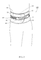
- FIG. 2 is a schematic drawing showing the back brace wound round the waist of a person
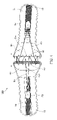
- FIG. 3 is a schematic drawing showing tightening adjustment of the back brace in accordance with the preferred embodiment of the present invention.
- FIG. 4 is a schematic drawing showing loosening adjustment of the back brace in accordance with the preferred embodiment of the present invention.
- a back brace 100 in accordance with a preferred embodiment of the present invention comprises a first brace member 10 , a second brace member 20 a first adjustment holder 30 , a second adjustment holder 40 two pull cords 50 and 60 and two fastening members 70 and 80 .
- the first brace member 10 comprises a first belt body 11 , a first support plate 12 , and a first connector 13 .
- the first belt body 11 is made out of a soft, slightly elastic, flexible material, defining a first outer surface 111 and a first inner surface 112 opposite to the first outer surface 111 .
- the first support plate 12 is a hard member fixedly fastened to the first outer surface 111 adjacent to one end of the first belt body 11 .
- the first connector 13 is a tape of loop member of a hook and loop fastener fixedly mounted on and extending along the major axis of the first belt body 11 .
- the second brace member 20 comprises a second belt body 21 , a second support plate 22 , a second connector 23 and a coupler 24 .
- the second belt body 21 is made out of a soft, slightly elastic, flexible material, defining a second outer surface 211 and a second inner surface 212 opposite to the second outer surface 211 .
- the second support plate 22 is a hard member fixedly fastened to the second outer surface 211 adjacent to one end of the second belt body 21 .
- the second connector 23 is a tape of loop member of a hook and loop fastener fixedly mounted on and extending along the major axis of the second belt body 21 .
- the coupler 24 is a tape of hook member of a hook and loop fastener fixedly mounted on the second inner surface 212 of the second belt body 21 remote from the second support plate 22 , and detachably connectable to the first connector 13 of the first brace member 10 .
- the first adjustment holder 30 comprises a first holder body 31 and a first rod member 32 .
- the first holder body 31 includes a first bottom shell 311 and a first top cover shell 312 .
- the first bottom shell 311 is fixedly bonded to the first support plate 12 of the first brace member 10 .
- the first bottom shell 311 has a plurality of first protrusions 313 spacedly arranged in a line adjacent to one end of the first belt body 11 .
- the first rod member 32 is a round rod supported on the first protrusions 313 , thereby defining a plurality of first insertion holes 314 in between each two adjacent protrusions 313 .
- the first top cover shell 312 is covered on the first bottom shell 311 so that the first rod member 32 is retained between the first bottom shell 311 and the first top cover shell 312 .
- the first top cover shell 312 has a plurality of openings 315 disposed in communication with the first insertion holes 314 .
- the second adjustment holder 40 comprises a second holder body 41 and a second rod member 42 .
- the second holder body 41 includes a second bottom shell 411 and a second top cover shell 412 .
- the second bottom shell 411 is fixedly bonded to the second support plate 22 of the second brace member 20 .
- the second bottom shell 411 has a plurality of second protrusions 413 spacedly arranged in a line adjacent to one end of the second belt body 21 .
- the second rod member 42 is a round rod supported on the second protrusions 413 , thereby defining a plurality of second insertion holes 414 in between each two adjacent protrusions 413 .
- the second top cover shell 412 is covered on the second bottom shell 411 so that the second rod member 42 is retained between the second bottom shell 411 and the second top cover shell 412 .
- the second top cover shell 412 has a plurality of openings 415 in communication with the second insertion holes 414 .
- One pull cord 50 is inserted through the first adjustment holder 30 and the second adjustment holder 40 and alternately running through the first insertion holes 314 on the upper half of the first brace member 10 and the second insertion holes 414 on the upper half of the second brace member 20 in a zigzag manner around the first rod member 32 and the second rod member 42 , and the two distal ends of the pull cord 50 are respectively extending out of the openings 315 and 415 of the first and second adjustment holder 30 and 40 .
- the other pull cord 60 is inserted through the first adjustment holder 30 and the second adjustment holder 40 and alternately running through the first insertion holes 314 on the lower half of the first brace member 10 and the second insertion holes 414 on the lower half of the second brace member 20 in a zigzag manner around the first rod member 32 and the second rod member 42 , and the two distal ends of the pull cord 60 are respectively extending out of the openings 315 and 415 of the first and second adjustment holder 30 and 40 .
- the two fastening members 70 and 80 are tapes of hook member of a hook and loop fastener.
- One fastening member 70 is fixedly connected with the ends of the two pull cords 50 and 60 that extend out of the openings 315 of the first adjustment holder 30 , and detachably connectable to the first connector 13 of the first brace member 10 .
- the other fastening member 80 is fixedly connected with the ends of the two pull cords 50 and 60 that extend out of the openings 415 of the second adjustment holder 40 , and detachably connectable to the second connector 23 of the second brace member 20 .
- the first brace member 10 and the second brace member 20 are attached around the user's waist or abdomen, and the coupler 24 of the second brace member 20 is fastened to the first connector 13 of the first brace member 10 , thereby securing the back brace 100 to the user's waist or abdomen and holding the first and second support plates 12 and 22 on the back side of the user's body to support the muscles of the user's back and to keep the user's lumbar spine in shape.
- the user uses the two hands to detach the two fastening members 70 and 80 from the first and second connectors 13 and 14 .
- the user can pull the two fastening members 70 and 80 in direction away from the first and second adjustment holders 30 and 40 to stretch the two pull cords 50 and 60 , causing the rod members 34 and 42 of the adjustment holders 30 and 40 to be moved toward each other subject to the desired tension and then the two fastening members 70 and 80 are respectively fastened to the first and second connectors 13 and 14 .
- the two fastening members 70 and 80 are respectively fastened to the first and second connectors 13 and 14 .
- the user can move the two fastening members 70 and 80 in direction toward the first and second adjustment holders 30 and 40 for allowing the first brace member 10 and the second brace member 20 to be pulled apart and then fasten the two fastening members 70 and 80 to the first and second connectors 13 and 14 .
- the user can conveniently adjust the tightness of the back brace 100 .
- the two pull cords 50 and 60 extend over the first and second rod members 32 and 42 of the first and second adjustment holders 30 and 40 in a zigzag manner, and therefore the user can pull the pull cords 50 and 60 to move the first and second rod members 32 and 42 of the first and second adjustment holders 30 and 40 toward each other efficiently with less effort. Therefore an old person, woman or patient can adjust the tightness of the back brace 100 easily. Further, because the invention is a mechanical design, the manufacturing cost is low.
- the back brace can be made using one single pull cord or more than two pull cords to achieve the same effect.
Landscapes
- Health & Medical Sciences (AREA)
- Nursing (AREA)
- Orthopedic Medicine & Surgery (AREA)
- Engineering & Computer Science (AREA)
- Biomedical Technology (AREA)
- Heart & Thoracic Surgery (AREA)
- Vascular Medicine (AREA)
- Life Sciences & Earth Sciences (AREA)
- Animal Behavior & Ethology (AREA)
- General Health & Medical Sciences (AREA)
- Public Health (AREA)
- Veterinary Medicine (AREA)
- Orthopedics, Nursing, And Contraception (AREA)
Abstract
Description
Claims (4)
Applications Claiming Priority (2)
| Application Number | Priority Date | Filing Date | Title |
|---|---|---|---|
| TW96218779 | 2007-11-07 | ||
| TW096218779U TWM330826U (en) | 2007-11-07 | 2007-11-07 | Pull string adjusting type waist-protecting restraint belt |
Publications (2)
| Publication Number | Publication Date |
|---|---|
| US20090118655A1 US20090118655A1 (en) | 2009-05-07 |
| US7727172B2 true US7727172B2 (en) | 2010-06-01 |
Family
ID=40588866
Family Applications (1)
| Application Number | Title | Priority Date | Filing Date |
|---|---|---|---|
| US12/034,240 Expired - Fee Related US7727172B2 (en) | 2007-11-07 | 2008-02-20 | Back brace having pull cord for size adjustment |
Country Status (2)
| Country | Link |
|---|---|
| US (1) | US7727172B2 (en) |
| TW (1) | TWM330826U (en) |
Cited By (31)
| Publication number | Priority date | Publication date | Assignee | Title |
|---|---|---|---|---|
| US20080319362A1 (en) * | 2007-06-20 | 2008-12-25 | Mark Joseph | Orthopedic System for Immobilizing and Supporting Body Parts |
| USD650485S1 (en) * | 2009-06-22 | 2011-12-13 | Sports & Supports Limited | Corset |
| USD663851S1 (en) | 2010-08-18 | 2012-07-17 | Exos Corporation | Short thumb spica brace |
| USD663850S1 (en) | 2010-08-18 | 2012-07-17 | Exos Corporation | Long thumb spica brace |
| USD665088S1 (en) | 2010-08-18 | 2012-08-07 | Exos Corporation | Wrist brace |
| USD666301S1 (en) * | 2011-12-08 | 2012-08-28 | Exos Corporation | Back brace |
| WO2013101833A1 (en) * | 2011-12-26 | 2013-07-04 | Hayes Victor | Multi-strap lumbar support device |
| US20140100501A1 (en) * | 2009-12-22 | 2014-04-10 | Aspen Medical Partners, Llc | Hyperextension Brace |
| US20140123370A1 (en) * | 2012-11-07 | 2014-05-08 | Huntex Corporation | Linked waist support for waist belt |
| US8795214B1 (en) * | 2010-07-19 | 2014-08-05 | Tony Conti | Orthotic brace and method of using |
| US20140276258A1 (en) * | 2013-03-15 | 2014-09-18 | Jacob Randy Hall | Cryotherapy compression system |
| US8864695B2 (en) | 2011-04-04 | 2014-10-21 | Todd M. Thornton | Adjustable brace apparatus |
| US20140364786A1 (en) * | 2013-06-07 | 2014-12-11 | University Braces, LLC | Universally adjustable lumbar brace |
| US8951217B2 (en) | 2009-02-24 | 2015-02-10 | Exos Llc | Composite material for custom fitted products |
| US9095418B2 (en) | 2013-03-15 | 2015-08-04 | Breg, Inc. | Anti-twist mechanism for a mechanical advantage tensioning device on an orthosis |
| US9295748B2 (en) | 2012-07-31 | 2016-03-29 | Exos Llc | Foam core sandwich splint |
| US9408738B2 (en) | 2012-08-01 | 2016-08-09 | Exos Llc | Orthopedic brace for animals |
| US20160310310A1 (en) * | 2015-04-24 | 2016-10-27 | Pelvicbinder, Inc. | Compression belts for selective chest compression following thoracic and cardiothoracic surgery and for selective abdominal compression following abdominal surgery |
| US9655761B2 (en) | 2012-11-12 | 2017-05-23 | Djo, Llc | Orthopedic back brace |
| US9795500B2 (en) | 2013-01-24 | 2017-10-24 | Ossur Hf | Orthopedic device for treating complications of the hip |
| USD816234S1 (en) * | 2016-10-31 | 2018-04-24 | GB Orthopedic Bracing LLC | Lumbar brace with cold pack |
| US9987158B2 (en) * | 2013-01-24 | 2018-06-05 | Ossur Hf | Orthopedic device for treating complications of the hip |
| CN108697521A (en) * | 2016-02-16 | 2018-10-23 | 鲍尔法因德股份有限公司 | Steering component at orthopaedics or medical auxiliary apparatus or assistant device for sport tool turning to or wherein rope |
| CN109963532A (en) * | 2016-11-11 | 2019-07-02 | 鲍尔法因德股份有限公司 | Tension band |
| US10357391B2 (en) | 2013-01-24 | 2019-07-23 | Ossur Hf | Orthopedic device for treating complications of the hip |
| US10420412B1 (en) * | 2019-02-26 | 2019-09-24 | Pressio LLC | Modular hip belt with gross and fine adjustment |
| US10973672B2 (en) * | 2015-04-24 | 2021-04-13 | Pelvicbinder, Inc. | Compression belts for selective chest compression following thoracic and cardiothoracic surgery and for rib fracture stabilization |
| US11324622B1 (en) | 2019-08-08 | 2022-05-10 | Preferred Prescription, Inc. | Back brace belt and apparatus, and method of belt length adjustment therefor |
| US11571323B2 (en) * | 2015-02-27 | 2023-02-07 | Ossur Iceland Ehf | Spinal orthosis, kit and method for using the same |
| USD989969S1 (en) | 2021-05-05 | 2023-06-20 | G Force Braces, Llc | Back brace |
| USD993426S1 (en) | 2021-05-05 | 2023-07-25 | G Force Braces, Llc | Back brace |
Families Citing this family (14)
| Publication number | Priority date | Publication date | Assignee | Title |
|---|---|---|---|---|
| USD636494S1 (en) | 2009-07-01 | 2011-04-19 | Aspen Medical Holdings | Lumbar belt |
| TWI424836B (en) * | 2011-02-16 | 2014-02-01 | Ming Yih Lee | Rigid automatic control of the waist control Huju |
| USD709614S1 (en) | 2013-02-07 | 2014-07-22 | Orthomerica Products, Inc. | Orthotic brace |
| MX381775B (en) | 2014-03-07 | 2025-03-13 | Fiji Mfg Llc | SUPPORT HAVING ELASTIC AND INELASTIC PORTIONS. |
| TWI601521B (en) * | 2015-11-13 | 2017-10-11 | Plus Meditech Co Ltd | Adjustable waist guard |
| GB2556877B (en) * | 2016-11-17 | 2022-04-06 | Neo G Ltd | Back brace |
| EP4431759A3 (en) | 2017-01-19 | 2024-12-18 | Vanderbilt University | Wearable assistance devices and methods of operation |
| US20200046539A1 (en) * | 2018-08-13 | 2020-02-13 | Khadijeh Jawed | Back support apparatus |
| FR3089407B1 (en) | 2018-12-05 | 2020-12-18 | Thuasne | Orthopedic belt with gripping elements |
| JP7254338B2 (en) * | 2019-02-28 | 2023-04-10 | 株式会社トップラン | orthotics |
| CA3142231A1 (en) | 2019-05-28 | 2020-12-03 | Vanderbilt University | Wearable assistance devices and methods of operation |
| US12138785B2 (en) | 2019-05-28 | 2024-11-12 | Vanderbilt University | Moment arm extension system for exosuit |
| US20230248602A1 (en) * | 2020-06-16 | 2023-08-10 | Vanderbilt University | Bimodal exosuit |
| CN218999629U (en) * | 2022-11-21 | 2023-05-12 | 东莞市福顺体育运动用品有限公司 | Novel waistband of elasticity is adjusted to knob |
Citations (5)
| Publication number | Priority date | Publication date | Assignee | Title |
|---|---|---|---|---|
| US5346461A (en) | 1992-10-23 | 1994-09-13 | Bio-Cybernetics International | Electromechanical back brace apparatus |
| US6213968B1 (en) * | 1998-06-18 | 2001-04-10 | Biocybernetics International | Custom fitted orthotic device |
| US6322529B1 (en) * | 2000-10-24 | 2001-11-27 | Joon Young Chung | Detachment type waist protecting belt |
| US20040139974A1 (en) * | 2000-12-05 | 2004-07-22 | Schwenn Shannon R. | Modular orthosis closure system and method |
| US7001348B2 (en) * | 2003-05-19 | 2006-02-21 | Aspen Medical Products | Double pull body brace |
-
2007
- 2007-11-07 TW TW096218779U patent/TWM330826U/en not_active IP Right Cessation
-
2008
- 2008-02-20 US US12/034,240 patent/US7727172B2/en not_active Expired - Fee Related
Patent Citations (5)
| Publication number | Priority date | Publication date | Assignee | Title |
|---|---|---|---|---|
| US5346461A (en) | 1992-10-23 | 1994-09-13 | Bio-Cybernetics International | Electromechanical back brace apparatus |
| US6213968B1 (en) * | 1998-06-18 | 2001-04-10 | Biocybernetics International | Custom fitted orthotic device |
| US6322529B1 (en) * | 2000-10-24 | 2001-11-27 | Joon Young Chung | Detachment type waist protecting belt |
| US20040139974A1 (en) * | 2000-12-05 | 2004-07-22 | Schwenn Shannon R. | Modular orthosis closure system and method |
| US7001348B2 (en) * | 2003-05-19 | 2006-02-21 | Aspen Medical Products | Double pull body brace |
Cited By (51)
| Publication number | Priority date | Publication date | Assignee | Title |
|---|---|---|---|---|
| US20080319362A1 (en) * | 2007-06-20 | 2008-12-25 | Mark Joseph | Orthopedic System for Immobilizing and Supporting Body Parts |
| US10463544B2 (en) | 2007-06-20 | 2019-11-05 | Djo, Llc | Orthopedic system for immobilizing and supporting body parts |
| US9561128B2 (en) | 2007-06-20 | 2017-02-07 | Exos Llc | Orthopedic system for immobilizing and supporting body parts |
| US8303527B2 (en) | 2007-06-20 | 2012-11-06 | Exos Corporation | Orthopedic system for immobilizing and supporting body parts |
| US10940031B2 (en) | 2009-02-24 | 2021-03-09 | Djo, Llc | Composite material for custom fitted products |
| US9757265B2 (en) | 2009-02-24 | 2017-09-12 | Djo, Llc | Composite material for custom fitted products |
| US8951217B2 (en) | 2009-02-24 | 2015-02-10 | Exos Llc | Composite material for custom fitted products |
| USD650485S1 (en) * | 2009-06-22 | 2011-12-13 | Sports & Supports Limited | Corset |
| US20140100501A1 (en) * | 2009-12-22 | 2014-04-10 | Aspen Medical Partners, Llc | Hyperextension Brace |
| US9186271B1 (en) * | 2010-07-19 | 2015-11-17 | Tony Conti | Orthotic brace and method of using |
| US8795214B1 (en) * | 2010-07-19 | 2014-08-05 | Tony Conti | Orthotic brace and method of using |
| USD663851S1 (en) | 2010-08-18 | 2012-07-17 | Exos Corporation | Short thumb spica brace |
| USD663850S1 (en) | 2010-08-18 | 2012-07-17 | Exos Corporation | Long thumb spica brace |
| USD665088S1 (en) | 2010-08-18 | 2012-08-07 | Exos Corporation | Wrist brace |
| US8864695B2 (en) | 2011-04-04 | 2014-10-21 | Todd M. Thornton | Adjustable brace apparatus |
| USD666301S1 (en) * | 2011-12-08 | 2012-08-28 | Exos Corporation | Back brace |
| WO2013101833A1 (en) * | 2011-12-26 | 2013-07-04 | Hayes Victor | Multi-strap lumbar support device |
| US10966856B2 (en) | 2012-07-31 | 2021-04-06 | Djo, Llc | Foam core sandwich splint |
| US9295748B2 (en) | 2012-07-31 | 2016-03-29 | Exos Llc | Foam core sandwich splint |
| US10285845B2 (en) | 2012-07-31 | 2019-05-14 | Djo, Llc | Foam core sandwich splint |
| US9408738B2 (en) | 2012-08-01 | 2016-08-09 | Exos Llc | Orthopedic brace for animals |
| US11191627B2 (en) | 2012-08-01 | 2021-12-07 | Djo, Llc | Orthopedic brace for animals |
| US20140123370A1 (en) * | 2012-11-07 | 2014-05-08 | Huntex Corporation | Linked waist support for waist belt |
| US9345279B2 (en) * | 2012-11-07 | 2016-05-24 | Huntex Corporation | Linked waist support for waist belt |
| US11484429B2 (en) | 2012-11-12 | 2022-11-01 | Djo, Llc | Orthopedic back brace |
| US9655761B2 (en) | 2012-11-12 | 2017-05-23 | Djo, Llc | Orthopedic back brace |
| US10517749B2 (en) | 2012-11-12 | 2019-12-31 | Djo, Llc | Orthopedic back brace |
| US9795500B2 (en) | 2013-01-24 | 2017-10-24 | Ossur Hf | Orthopedic device for treating complications of the hip |
| US11259948B2 (en) | 2013-01-24 | 2022-03-01 | Ossur Hf | Orthopedic device for treating complications of the hip |
| US9987158B2 (en) * | 2013-01-24 | 2018-06-05 | Ossur Hf | Orthopedic device for treating complications of the hip |
| US12433778B2 (en) | 2013-01-24 | 2025-10-07 | Ossur Hf | Orthopedic device for treating complications of the hip |
| US10357391B2 (en) | 2013-01-24 | 2019-07-23 | Ossur Hf | Orthopedic device for treating complications of the hip |
| US20140276258A1 (en) * | 2013-03-15 | 2014-09-18 | Jacob Randy Hall | Cryotherapy compression system |
| US9095418B2 (en) | 2013-03-15 | 2015-08-04 | Breg, Inc. | Anti-twist mechanism for a mechanical advantage tensioning device on an orthosis |
| US10555863B2 (en) * | 2013-03-15 | 2020-02-11 | Jacob Randy Hall | Cryotherapy compression system |
| US20140364786A1 (en) * | 2013-06-07 | 2014-12-11 | University Braces, LLC | Universally adjustable lumbar brace |
| CN104758107A (en) * | 2013-06-07 | 2015-07-08 | 大学贝思有限责任公司 | Universally adjustable lumbar brace |
| US11571323B2 (en) * | 2015-02-27 | 2023-02-07 | Ossur Iceland Ehf | Spinal orthosis, kit and method for using the same |
| US20160310310A1 (en) * | 2015-04-24 | 2016-10-27 | Pelvicbinder, Inc. | Compression belts for selective chest compression following thoracic and cardiothoracic surgery and for selective abdominal compression following abdominal surgery |
| US10973672B2 (en) * | 2015-04-24 | 2021-04-13 | Pelvicbinder, Inc. | Compression belts for selective chest compression following thoracic and cardiothoracic surgery and for rib fracture stabilization |
| US10092440B2 (en) * | 2015-04-24 | 2018-10-09 | Pelvicbinder, Inc. | Compression belts for selective chest compression following thoracic and cardiothoracic surgery and for selective abdominal compression following abdominal surgery |
| CN108697521A (en) * | 2016-02-16 | 2018-10-23 | 鲍尔法因德股份有限公司 | Steering component at orthopaedics or medical auxiliary apparatus or assistant device for sport tool turning to or wherein rope |
| USD816234S1 (en) * | 2016-10-31 | 2018-04-24 | GB Orthopedic Bracing LLC | Lumbar brace with cold pack |
| CN109963532B (en) * | 2016-11-11 | 2022-03-29 | 鲍尔法因德股份有限公司 | tension belt |
| CN109963532A (en) * | 2016-11-11 | 2019-07-02 | 鲍尔法因德股份有限公司 | Tension band |
| US10420412B1 (en) * | 2019-02-26 | 2019-09-24 | Pressio LLC | Modular hip belt with gross and fine adjustment |
| US10638827B1 (en) * | 2019-02-26 | 2020-05-05 | Pressio LLC | Modular hip belt with gross and fine adjustment |
| US11324622B1 (en) | 2019-08-08 | 2022-05-10 | Preferred Prescription, Inc. | Back brace belt and apparatus, and method of belt length adjustment therefor |
| US12357490B2 (en) | 2019-08-08 | 2025-07-15 | Preferred Prescription, Inc. | Back brace with enhanced height support and adjustment capability |
| USD989969S1 (en) | 2021-05-05 | 2023-06-20 | G Force Braces, Llc | Back brace |
| USD993426S1 (en) | 2021-05-05 | 2023-07-25 | G Force Braces, Llc | Back brace |
Also Published As
| Publication number | Publication date |
|---|---|
| TWM330826U (en) | 2008-04-21 |
| US20090118655A1 (en) | 2009-05-07 |
Similar Documents
| Publication | Publication Date | Title |
|---|---|---|
| US7727172B2 (en) | Back brace having pull cord for size adjustment | |
| US10716696B2 (en) | Dorsal lumbar extension brace with tensioning system | |
| US7186229B2 (en) | Modular orthosis closure system and method | |
| US20130237891A1 (en) | Orthotic brace tightening device | |
| US7118543B2 (en) | Orthosis closure system with mechanical advantage | |
| US8808213B2 (en) | Mechanically advantaged spinal system and method | |
| EP2223669A1 (en) | Highly adjustable lumbar support and methods | |
| US9339693B1 (en) | Weight lifting strap with equipment engagement system | |
| KR101425522B1 (en) | spine brace | |
| CN103582467A (en) | Adjustable brace apparatus | |
| US20210038419A1 (en) | Portable traction device with sling | |
| KR20130122596A (en) | Waist belt | |
| US9095418B2 (en) | Anti-twist mechanism for a mechanical advantage tensioning device on an orthosis | |
| KR102204533B1 (en) | belts for towing waist | |
| US5415183A (en) | Harness for abdominal catheter support band | |
| CN213283612U (en) | Adjustable waistband of pulley backplate | |
| US20240307208A1 (en) | Back support brace and method of wearing same | |
| KR100799718B1 (en) | Waistguard | |
| US20190192330A1 (en) | Single Pull Lumbar Support Brace | |
| CN210672107U (en) | Body shaping clothes with adjustable tightness | |
| CN217908107U (en) | Lumbar vertebra supporting device convenient to adjust | |
| CN220655754U (en) | Medical lumbar vertebra fixer | |
| CN219230294U (en) | External fixing device for binder convenient to disassemble and assemble | |
| US20150126918A1 (en) | Universal spine brace with cable tensioning system | |
| KR200198649Y1 (en) | Medical body jackets |
Legal Events
| Date | Code | Title | Description |
|---|---|---|---|
| AS | Assignment |
Owner name: KAO CHEN ENTERPRISE CO., LTD., TAIWAN Free format text: ASSIGNMENT OF ASSIGNORS INTEREST;ASSIGNOR:WANG, CHIH-CHUAN;REEL/FRAME:020584/0376 Effective date: 20080214 Owner name: KAO CHEN ENTERPRISE CO., LTD.,TAIWAN Free format text: ASSIGNMENT OF ASSIGNORS INTEREST;ASSIGNOR:WANG, CHIH-CHUAN;REEL/FRAME:020584/0376 Effective date: 20080214 |
|
| REMI | Maintenance fee reminder mailed | ||
| LAPS | Lapse for failure to pay maintenance fees | ||
| STCH | Information on status: patent discontinuation |
Free format text: PATENT EXPIRED DUE TO NONPAYMENT OF MAINTENANCE FEES UNDER 37 CFR 1.362 |
|
| STCH | Information on status: patent discontinuation |
Free format text: PATENT EXPIRED DUE TO NONPAYMENT OF MAINTENANCE FEES UNDER 37 CFR 1.362 |
|
| FP | Lapsed due to failure to pay maintenance fee |
Effective date: 20140601 |