US7724452B2 - Optical lens assembly and lens module - Google Patents
Optical lens assembly and lens module Download PDFInfo
- Publication number
- US7724452B2 US7724452B2 US12/248,287 US24828708A US7724452B2 US 7724452 B2 US7724452 B2 US 7724452B2 US 24828708 A US24828708 A US 24828708A US 7724452 B2 US7724452 B2 US 7724452B2
- Authority
- US
- United States
- Prior art keywords
- lens
- facing surface
- stepped portion
- annular stepped
- upward
- Prior art date
- Legal status (The legal status is an assumption and is not a legal conclusion. Google has not performed a legal analysis and makes no representation as to the accuracy of the status listed.)
- Expired - Fee Related
Links
- 230000003287 optical effect Effects 0.000 title claims abstract description 26
- 230000002093 peripheral effect Effects 0.000 description 3
- 230000001413 cellular effect Effects 0.000 description 1
- 230000001419 dependent effect Effects 0.000 description 1
- 239000011521 glass Substances 0.000 description 1
- 238000004519 manufacturing process Methods 0.000 description 1
- 239000000463 material Substances 0.000 description 1
- 238000012634 optical imaging Methods 0.000 description 1
Images


Classifications
-
- G—PHYSICS
- G02—OPTICS
- G02B—OPTICAL ELEMENTS, SYSTEMS OR APPARATUS
- G02B13/00—Optical objectives specially designed for the purposes specified below
- G02B13/001—Miniaturised objectives for electronic devices, e.g. portable telephones, webcams, PDAs, small digital cameras
- G02B13/0015—Miniaturised objectives for electronic devices, e.g. portable telephones, webcams, PDAs, small digital cameras characterised by the lens design
- G02B13/005—Miniaturised objectives for electronic devices, e.g. portable telephones, webcams, PDAs, small digital cameras characterised by the lens design having spherical lenses only
Definitions
- the present invention relates to optical imaging devices and, particularly, to an optical lens assembly and a lens module having the same.
- image pick-up apparatuses have become widely used in a variety of consumer electronic devices, such as notebook computers, personal digital assistants (PDAs), cellular telephones, etc.
- PDAs personal digital assistants
- demand for improving image quality is increasing, which is essentially dependent on the quality of a lens module of the image pick-up apparatus. That is, a lens module with high image quality is desired.
- an optical lens assembly 20 includes two lenses 24 , 26 .
- the lens 24 and lens 26 each has a central round portion and a peripheral portion.
- the peripheral portion of the lens 24 includes a protuberance 242
- the peripheral portion of the lens 26 includes a protuberance 262 coupled with the protuberance 242 .
- the protuberance 242 has a surface 244 and the protuberance 262 has a surface 264 .
- the two surfaces 244 , 264 are both incline planes and have the same gradient. When assembling the two lenses 24 and 26 , the surfaces 244 and 264 contact each other to engage the lens 24 to the lens 26 . However, this combination requires the manufacturing tolerance of the incline plane to be very precise.
- the inside depth of the lens 26 to lens 24 will be different. This will make the distance between the two lenses 24 and 26 fail to meet specification. The location of contact between the two lenses 24 , 26 will be unstable and may cause the lens 26 to become skewed. Furthermore, the axis of the lenses 24 and 26 will not be coincident. Thus, a lens module having the optical lens assembly 20 above may provide distorted images.
- An exemplary optical lens assembly includes a first lens and a second lens.
- the first lens comprises a first central portion and a first annular stepped portion surrounding the first central portion.
- the first annular stepped portion has a first outer step and a second outer step.
- the first outer step has a first outer side surface and a first downward-facing surface.
- the second outer step has a second outer side surface and a second downward-facing surface.
- the second lens comprises a second central portion and a second annular stepped portion surrounding the second central portion.
- the second annular stepped portion has a first inner step and a second inner step.
- the first inner step has a first inner side surface and a first upward-facing surface.
- the second inner step has a second inner side surface and a second upward-facing surface.
- the first annular stepped portion is engaged in the second annular stepped portion.
- the first outer side surface is in contact with the second inner side surface.
- the first downward-facing surface is in contact with the first upward-facing surface.
- a gap exists between the second outer side surface and the first inner side surface.
- FIG. 1 is a disassembled, cross-sectional view of an optical lens assembly according to an exemplary embodiment.
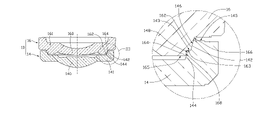
- FIG. 2 is an assembled, cross-sectional view of the optical lens assembly shown in FIG. 1 .
- FIG. 3 is an enlarged view of an area III of the optical lens assembly shown in FIG. 2 .
- FIG. 4 is an assembled, cross-sectional view of a lens module according to an exemplary embodiment.
- FIG. 5 is a schematic, cross-sectional view of a typical optical lens assembly.
- the optical lens assembly 10 includes a first lens 16 and a second lens 14 .
- the first lens 16 and the second lens 14 can be made of plastic, glass or other optical materials known in the art.
- the first lens 16 includes a first central portion 160 and a first annular stepped portion 161 surrounding the first central portion 160 .
- the first central portion 160 is configured for cooperating with other elements to capture images.
- the first annular stepped portion 161 has a first outer step 162 and a second outer step 164 .
- the first outer step 162 and the second outer step 164 are annular steps surrounding the first central portion 160 of the first lens 16 .
- the first outer step 162 has a first outer side surface 166 and a first downward-facing surface 163 .
- the second outer step 164 has a second outer side surface 168 and a second downward-facing surface 165 .
- the first downward-facing surface 163 adjoins the second outer side surface 168 .
- the second lens 14 includes a second central portion 140 and a second annular stepped portion 141 surrounding the second central portion 140 .
- the second central portion 140 is configured for cooperating with other elements to capture images.
- the second annular stepped portion 141 has a first inner step 144 and a second inner step 142 .
- the first inner step 144 and the second inner step 142 are annular steps surrounding the second central portion 140 of the second lens 14 .
- the first inner step 144 has a first inner side surface 148 and a first upward-facing surface 143 .
- the second inner step 142 has a second inner side surface 146 and a second upward-facing surface 145 .
- the first upward-facing surface 143 adjoins the second inner side surface 148 .
- the first annular stepped portion 161 is engaged in the second annular stepped portion 141 .
- the first outer side surface 166 is in contact with the second inner side surface 146 .
- the first and second outer steps 162 , 164 taper in a direction toward the second lens 14 .
- the first and second outer steps 162 , 164 have a same tapering degree. So the first outer step 162 of the first lens 16 can be received by the first inner step 144 .
- the first downward-facing surface 163 is in contact with the first upward-facing surface 143 .
- the first upward-facing surface 143 contacting with the first downward-facing surface 163 ensures a fixed distance between the first lens 16 and the second lens 14 .
- the second downward-facing step surface 165 of the first lens 16 is spaced apart from the second lens 14 .
- the second upward-facing step surface 145 of the second lens 14 is spaced apart from the first lens 16 .
- a gap exists between the second outer side surface 168 and the first inner side surface 148 . Assembly of the optical lens assembly by fixing the first lens 16 to the second lens 14 will be easier because a gap is allowed between the first inner side surface 148 and the second outer side surface 168 so no friction between the two surfaces 148 , 168 will occur to make fitting difficult.
- the first outer side surface 166 is guided by the second inner side surface 146 .
- the first downward-facing surface 163 is in contact with the first upward-facing surface 143 , the first lens 16 can be fixed to the second lens 14 .
- the gap allows easier assembly while contact between the surfaces assures accurate positioning.
- the axis of the lenses 16 and 14 will be coincident.
- a lens module having the optical lens assembly 10 will be easy and convenient to accurately assemble and provide better image quality.
- the lens module 30 includes a barrel 32 , and receives the lens assembly 10 therein.
Landscapes
- Physics & Mathematics (AREA)
- General Physics & Mathematics (AREA)
- Optics & Photonics (AREA)
- Lenses (AREA)
- Lens Barrels (AREA)
Abstract
Description
Claims (14)
Priority Applications (1)
| Application Number | Priority Date | Filing Date | Title |
|---|---|---|---|
| JP2011527794A JP2012514734A (en) | 2008-09-19 | 2009-05-21 | High resolution PET breast imager with improved detection efficiency |
Applications Claiming Priority (2)
| Application Number | Priority Date | Filing Date | Title |
|---|---|---|---|
| CN2008103004761A CN101526656B (en) | 2008-03-05 | 2008-03-05 | Optical lens group |
| CN200810300476.1 | 2008-03-05 |
Publications (2)
| Publication Number | Publication Date |
|---|---|
| US20090225446A1 US20090225446A1 (en) | 2009-09-10 |
| US7724452B2 true US7724452B2 (en) | 2010-05-25 |
Family
ID=41053345
Family Applications (1)
| Application Number | Title | Priority Date | Filing Date |
|---|---|---|---|
| US12/248,287 Expired - Fee Related US7724452B2 (en) | 2008-03-05 | 2008-10-09 | Optical lens assembly and lens module |
Country Status (2)
| Country | Link |
|---|---|
| US (1) | US7724452B2 (en) |
| CN (1) | CN101526656B (en) |
Cited By (5)
| Publication number | Priority date | Publication date | Assignee | Title |
|---|---|---|---|---|
| US20120044588A1 (en) * | 2010-08-19 | 2012-02-23 | Hon Hai Precision Industry Co., Ltd. | Optical lens and lens assembly having same |
| US8830600B2 (en) * | 2013-01-18 | 2014-09-09 | Glory Science Co., Ltd. | Lens module |
| US10133037B2 (en) | 2016-08-26 | 2018-11-20 | Largan Precision Co., Ltd. | Optical path folding element, imaging lens module and electronic device |
| US12007589B2 (en) | 2021-05-14 | 2024-06-11 | Largan Precision Co., Ltd. | Imaging lens system, image capturing module and electronic device |
| US12429663B2 (en) | 2021-04-30 | 2025-09-30 | Largan Precision Co., Ltd. | Imaging lens assembly, image capturing apparatus and electronic device |
Families Citing this family (4)
| Publication number | Priority date | Publication date | Assignee | Title |
|---|---|---|---|---|
| CN102033284A (en) * | 2009-09-28 | 2011-04-27 | 鸿富锦精密工业(深圳)有限公司 | Lens clamping structure and lens module applying same |
| CN104865680B (en) * | 2015-06-15 | 2018-05-22 | 广东旭业光电科技股份有限公司 | Optical lens and electronic device using same |
| CN111897081A (en) * | 2019-05-06 | 2020-11-06 | 南昌欧菲精密光学制品有限公司 | Lens barrel, lens structure and assembly method thereof, and camera module |
| CN112540436B (en) * | 2019-09-04 | 2023-06-06 | 宁波舜宇光电信息有限公司 | Split lens, first lens part, testing method, assembling method and camera module |
Citations (2)
| Publication number | Priority date | Publication date | Assignee | Title |
|---|---|---|---|---|
| US7268957B2 (en) * | 2003-09-26 | 2007-09-11 | Siemens Aktiengesellschaft | Optical module and optical system |
| US20090168204A1 (en) * | 2005-12-13 | 2009-07-02 | Panasonic Corporation | Lens, lens unit, and imaging device using the same |
Family Cites Families (1)
| Publication number | Priority date | Publication date | Assignee | Title |
|---|---|---|---|---|
| KR200347020Y1 (en) * | 2004-01-14 | 2004-04-03 | 뉴바이오 (주) | Injection molding machine of a mold in a contact lens |
-
2008
- 2008-03-05 CN CN2008103004761A patent/CN101526656B/en not_active Expired - Fee Related
- 2008-10-09 US US12/248,287 patent/US7724452B2/en not_active Expired - Fee Related
Patent Citations (2)
| Publication number | Priority date | Publication date | Assignee | Title |
|---|---|---|---|---|
| US7268957B2 (en) * | 2003-09-26 | 2007-09-11 | Siemens Aktiengesellschaft | Optical module and optical system |
| US20090168204A1 (en) * | 2005-12-13 | 2009-07-02 | Panasonic Corporation | Lens, lens unit, and imaging device using the same |
Cited By (10)
| Publication number | Priority date | Publication date | Assignee | Title |
|---|---|---|---|---|
| US20120044588A1 (en) * | 2010-08-19 | 2012-02-23 | Hon Hai Precision Industry Co., Ltd. | Optical lens and lens assembly having same |
| US8243374B2 (en) * | 2010-08-19 | 2012-08-14 | Hon Hai Precision Industry Co., Ltd. | Optical lens and lens assembly having same |
| US8830600B2 (en) * | 2013-01-18 | 2014-09-09 | Glory Science Co., Ltd. | Lens module |
| US10133037B2 (en) | 2016-08-26 | 2018-11-20 | Largan Precision Co., Ltd. | Optical path folding element, imaging lens module and electronic device |
| US10663697B2 (en) | 2016-08-26 | 2020-05-26 | Largan Precision Co., Ltd. | Optical path folding element, imaging lens module and electronic device |
| US11333865B2 (en) | 2016-08-26 | 2022-05-17 | Largan Precision Co., Ltd. | Optical path folding element, imaging lens module and electronic device |
| US11921267B2 (en) | 2016-08-26 | 2024-03-05 | Largan Precision Co., Ltd. | Optical path folding element, imaging lens module and electronic device |
| US12429663B2 (en) | 2021-04-30 | 2025-09-30 | Largan Precision Co., Ltd. | Imaging lens assembly, image capturing apparatus and electronic device |
| US12007589B2 (en) | 2021-05-14 | 2024-06-11 | Largan Precision Co., Ltd. | Imaging lens system, image capturing module and electronic device |
| US12449571B2 (en) | 2021-05-14 | 2025-10-21 | Largan Precision Co., Ltd. | Imaging lens system, image capturing module and electronic device |
Also Published As
| Publication number | Publication date |
|---|---|
| CN101526656B (en) | 2011-06-08 |
| US20090225446A1 (en) | 2009-09-10 |
| CN101526656A (en) | 2009-09-09 |
Similar Documents
| Publication | Publication Date | Title |
|---|---|---|
| US7724452B2 (en) | Optical lens assembly and lens module | |
| US7813058B2 (en) | Optical lens group and related lens module | |
| US8014655B2 (en) | Camera module | |
| US7755857B2 (en) | Lens module | |
| US7738196B2 (en) | Optical unit | |
| US9817205B2 (en) | Lens module | |
| US8169721B2 (en) | Lens assembly and lens module incorporating the same | |
| US20170139176A1 (en) | Lens Module | |
| US7755858B2 (en) | Lens assembly and lens module having same | |
| CN109643002A (en) | Lens unit | |
| CN110389482B (en) | Annular optical element and imaging lens | |
| US20100027137A1 (en) | Lens module | |
| US20240036287A1 (en) | Imaging lens system, camera module and electronic device | |
| CN110398814B (en) | Annular optical element and imaging lens module | |
| CN101571618B (en) | Lens module, camera module with lens module and assembly method thereof | |
| US11029581B2 (en) | Camera lens | |
| US11029482B2 (en) | Pressing ring and lens module | |
| US20210055511A1 (en) | Lens module of reduced size and electronic device having the same | |
| US7755856B2 (en) | Lens module and optical module incorporating same | |
| US20090290237A1 (en) | Lens assembly and lens module incorporating the same | |
| US20110158636A1 (en) | Lens assembly and camera module using the same | |
| US20200041749A1 (en) | Lens and lens module including the same | |
| TWI416190B (en) | Spacer ring and lens module having the same | |
| TW201202778A (en) | Lens barrel and lens module having same | |
| CN102298187A (en) | Lens module |
Legal Events
| Date | Code | Title | Description |
|---|---|---|---|
| AS | Assignment |
Owner name: HON HAI PRECISION INDUSTRY CO., LTD., TAIWAN Free format text: ASSIGNMENT OF ASSIGNORS INTEREST;ASSIGNOR:HUANG, CHIEN-FENG;REEL/FRAME:021655/0088 Effective date: 20080918 Owner name: HON HAI PRECISION INDUSTRY CO., LTD.,TAIWAN Free format text: ASSIGNMENT OF ASSIGNORS INTEREST;ASSIGNOR:HUANG, CHIEN-FENG;REEL/FRAME:021655/0088 Effective date: 20080918 |
|
| STCF | Information on status: patent grant |
Free format text: PATENTED CASE |
|
| FPAY | Fee payment |
Year of fee payment: 4 |
|
| MAFP | Maintenance fee payment |
Free format text: PAYMENT OF MAINTENANCE FEE, 8TH YEAR, LARGE ENTITY (ORIGINAL EVENT CODE: M1552) Year of fee payment: 8 |
|
| FEPP | Fee payment procedure |
Free format text: MAINTENANCE FEE REMINDER MAILED (ORIGINAL EVENT CODE: REM.); ENTITY STATUS OF PATENT OWNER: LARGE ENTITY |
|
| LAPS | Lapse for failure to pay maintenance fees |
Free format text: PATENT EXPIRED FOR FAILURE TO PAY MAINTENANCE FEES (ORIGINAL EVENT CODE: EXP.); ENTITY STATUS OF PATENT OWNER: LARGE ENTITY |
|
| STCH | Information on status: patent discontinuation |
Free format text: PATENT EXPIRED DUE TO NONPAYMENT OF MAINTENANCE FEES UNDER 37 CFR 1.362 |
|
| STCH | Information on status: patent discontinuation |
Free format text: PATENT EXPIRED DUE TO NONPAYMENT OF MAINTENANCE FEES UNDER 37 CFR 1.362 |
|
| FP | Lapsed due to failure to pay maintenance fee |
Effective date: 20220525 |