US7723936B2 - Method for controlled braking of a door and device for applying said method - Google Patents
Method for controlled braking of a door and device for applying said method Download PDFInfo
- Publication number
- US7723936B2 US7723936B2 US11/829,355 US82935507A US7723936B2 US 7723936 B2 US7723936 B2 US 7723936B2 US 82935507 A US82935507 A US 82935507A US 7723936 B2 US7723936 B2 US 7723936B2
- Authority
- US
- United States
- Prior art keywords
- door
- braking
- control device
- stopping process
- nominal
- Prior art date
- Legal status (The legal status is an assumption and is not a legal conclusion. Google has not performed a legal analysis and makes no representation as to the accuracy of the status listed.)
- Active, expires
Links
Images


Classifications
-
- G—PHYSICS
- G05—CONTROLLING; REGULATING
- G05B—CONTROL OR REGULATING SYSTEMS IN GENERAL; FUNCTIONAL ELEMENTS OF SUCH SYSTEMS; MONITORING OR TESTING ARRANGEMENTS FOR SUCH SYSTEMS OR ELEMENTS
- G05B19/00—Programme-control systems
- G05B19/02—Programme-control systems electric
- G05B19/18—Numerical control [NC], i.e. automatically operating machines, in particular machine tools, e.g. in a manufacturing environment, so as to execute positioning, movement or co-ordinated operations by means of programme data in numerical form
- G05B19/416—Numerical control [NC], i.e. automatically operating machines, in particular machine tools, e.g. in a manufacturing environment, so as to execute positioning, movement or co-ordinated operations by means of programme data in numerical form characterised by control of velocity, acceleration or deceleration
-
- E—FIXED CONSTRUCTIONS
- E05—LOCKS; KEYS; WINDOW OR DOOR FITTINGS; SAFES
- E05F—DEVICES FOR MOVING WINGS INTO OPEN OR CLOSED POSITION; CHECKS FOR WINGS; WING FITTINGS NOT OTHERWISE PROVIDED FOR, CONCERNED WITH THE FUNCTIONING OF THE WING
- E05F15/00—Power-operated mechanisms for wings
- E05F15/40—Safety devices, e.g. detection of obstructions or end positions
-
- E—FIXED CONSTRUCTIONS
- E06—DOORS, WINDOWS, SHUTTERS, OR ROLLER BLINDS IN GENERAL; LADDERS
- E06B—FIXED OR MOVABLE CLOSURES FOR OPENINGS IN BUILDINGS, VEHICLES, FENCES OR LIKE ENCLOSURES IN GENERAL, e.g. DOORS, WINDOWS, BLINDS, GATES
- E06B9/00—Screening or protective devices for wall or similar openings, with or without operating or securing mechanisms; Closures of similar construction
- E06B9/56—Operating, guiding or securing devices or arrangements for roll-type closures; Spring drums; Tape drums; Counterweighting arrangements therefor
- E06B9/80—Safety measures against dropping or unauthorised opening; Braking or immobilising devices; Devices for limiting unrolling
- E06B9/82—Safety measures against dropping or unauthorised opening; Braking or immobilising devices; Devices for limiting unrolling automatic
- E06B9/84—Safety measures against dropping or unauthorised opening; Braking or immobilising devices; Devices for limiting unrolling automatic against dropping
-
- E—FIXED CONSTRUCTIONS
- E05—LOCKS; KEYS; WINDOW OR DOOR FITTINGS; SAFES
- E05D—HINGES OR SUSPENSION DEVICES FOR DOORS, WINDOWS OR WINGS
- E05D13/00—Accessories for sliding or lifting wings, e.g. pulleys, safety catches
- E05D13/003—Anti-dropping devices
-
- E—FIXED CONSTRUCTIONS
- E05—LOCKS; KEYS; WINDOW OR DOOR FITTINGS; SAFES
- E05F—DEVICES FOR MOVING WINGS INTO OPEN OR CLOSED POSITION; CHECKS FOR WINGS; WING FITTINGS NOT OTHERWISE PROVIDED FOR, CONCERNED WITH THE FUNCTIONING OF THE WING
- E05F15/00—Power-operated mechanisms for wings
-
- E—FIXED CONSTRUCTIONS
- E05—LOCKS; KEYS; WINDOW OR DOOR FITTINGS; SAFES
- E05F—DEVICES FOR MOVING WINGS INTO OPEN OR CLOSED POSITION; CHECKS FOR WINGS; WING FITTINGS NOT OTHERWISE PROVIDED FOR, CONCERNED WITH THE FUNCTIONING OF THE WING
- E05F15/00—Power-operated mechanisms for wings
- E05F15/60—Power-operated mechanisms for wings using electrical actuators
- E05F15/603—Power-operated mechanisms for wings using electrical actuators using rotary electromotors
- E05F15/665—Power-operated mechanisms for wings using electrical actuators using rotary electromotors for vertically-sliding wings
- E05F15/668—Power-operated mechanisms for wings using electrical actuators using rotary electromotors for vertically-sliding wings for overhead wings
-
- E—FIXED CONSTRUCTIONS
- E05—LOCKS; KEYS; WINDOW OR DOOR FITTINGS; SAFES
- E05F—DEVICES FOR MOVING WINGS INTO OPEN OR CLOSED POSITION; CHECKS FOR WINGS; WING FITTINGS NOT OTHERWISE PROVIDED FOR, CONCERNED WITH THE FUNCTIONING OF THE WING
- E05F15/00—Power-operated mechanisms for wings
- E05F15/70—Power-operated mechanisms for wings with automatic actuation
- E05F15/72—Power-operated mechanisms for wings with automatic actuation responsive to emergency conditions, e.g. fire
-
- E—FIXED CONSTRUCTIONS
- E05—LOCKS; KEYS; WINDOW OR DOOR FITTINGS; SAFES
- E05Y—INDEXING SCHEME RELATING TO HINGES OR OTHER SUSPENSION DEVICES FOR DOORS, WINDOWS OR WINGS AND DEVICES FOR MOVING WINGS INTO OPEN OR CLOSED POSITION, CHECKS FOR WINGS AND WING FITTINGS NOT OTHERWISE PROVIDED FOR, CONCERNED WITH THE FUNCTIONING OF THE WING
- E05Y2201/00—Constructional elements; Accessories therefore
- E05Y2201/20—Brakes; Disengaging means, e.g. clutches; Holders, e.g. locks; Stops; Accessories therefore
- E05Y2201/21—Brakes
-
- E—FIXED CONSTRUCTIONS
- E05—LOCKS; KEYS; WINDOW OR DOOR FITTINGS; SAFES
- E05Y—INDEXING SCHEME RELATING TO HINGES OR OTHER SUSPENSION DEVICES FOR DOORS, WINDOWS OR WINGS AND DEVICES FOR MOVING WINGS INTO OPEN OR CLOSED POSITION, CHECKS FOR WINGS AND WING FITTINGS NOT OTHERWISE PROVIDED FOR, CONCERNED WITH THE FUNCTIONING OF THE WING
- E05Y2201/00—Constructional elements; Accessories therefore
- E05Y2201/20—Brakes; Disengaging means, e.g. clutches; Holders, e.g. locks; Stops; Accessories therefore
- E05Y2201/23—Actuation thereof
- E05Y2201/246—Actuation thereof by motors, magnets, springs or weights
-
- E—FIXED CONSTRUCTIONS
- E05—LOCKS; KEYS; WINDOW OR DOOR FITTINGS; SAFES
- E05Y—INDEXING SCHEME RELATING TO HINGES OR OTHER SUSPENSION DEVICES FOR DOORS, WINDOWS OR WINGS AND DEVICES FOR MOVING WINGS INTO OPEN OR CLOSED POSITION, CHECKS FOR WINGS AND WING FITTINGS NOT OTHERWISE PROVIDED FOR, CONCERNED WITH THE FUNCTIONING OF THE WING
- E05Y2201/00—Constructional elements; Accessories therefore
- E05Y2201/20—Brakes; Disengaging means, e.g. clutches; Holders, e.g. locks; Stops; Accessories therefore
- E05Y2201/252—Brakes; Disengaging means, e.g. clutches; Holders, e.g. locks; Stops; Accessories therefore characterised by type of friction
- E05Y2201/26—Mechanical friction
-
- E—FIXED CONSTRUCTIONS
- E05—LOCKS; KEYS; WINDOW OR DOOR FITTINGS; SAFES
- E05Y—INDEXING SCHEME RELATING TO HINGES OR OTHER SUSPENSION DEVICES FOR DOORS, WINDOWS OR WINGS AND DEVICES FOR MOVING WINGS INTO OPEN OR CLOSED POSITION, CHECKS FOR WINGS AND WING FITTINGS NOT OTHERWISE PROVIDED FOR, CONCERNED WITH THE FUNCTIONING OF THE WING
- E05Y2201/00—Constructional elements; Accessories therefore
- E05Y2201/20—Brakes; Disengaging means, e.g. clutches; Holders, e.g. locks; Stops; Accessories therefore
- E05Y2201/262—Brakes; Disengaging means, e.g. clutches; Holders, e.g. locks; Stops; Accessories therefore characterised by type of motion
- E05Y2201/266—Brakes; Disengaging means, e.g. clutches; Holders, e.g. locks; Stops; Accessories therefore characterised by type of motion rotary
-
- E—FIXED CONSTRUCTIONS
- E05—LOCKS; KEYS; WINDOW OR DOOR FITTINGS; SAFES
- E05Y—INDEXING SCHEME RELATING TO HINGES OR OTHER SUSPENSION DEVICES FOR DOORS, WINDOWS OR WINGS AND DEVICES FOR MOVING WINGS INTO OPEN OR CLOSED POSITION, CHECKS FOR WINGS AND WING FITTINGS NOT OTHERWISE PROVIDED FOR, CONCERNED WITH THE FUNCTIONING OF THE WING
- E05Y2201/00—Constructional elements; Accessories therefore
- E05Y2201/40—Motors; Magnets; Springs; Weights; Accessories therefore
- E05Y2201/43—Motors
- E05Y2201/434—Electromotors; Details thereof
-
- E—FIXED CONSTRUCTIONS
- E05—LOCKS; KEYS; WINDOW OR DOOR FITTINGS; SAFES
- E05Y—INDEXING SCHEME RELATING TO HINGES OR OTHER SUSPENSION DEVICES FOR DOORS, WINDOWS OR WINGS AND DEVICES FOR MOVING WINGS INTO OPEN OR CLOSED POSITION, CHECKS FOR WINGS AND WING FITTINGS NOT OTHERWISE PROVIDED FOR, CONCERNED WITH THE FUNCTIONING OF THE WING
- E05Y2201/00—Constructional elements; Accessories therefore
- E05Y2201/40—Motors; Magnets; Springs; Weights; Accessories therefore
- E05Y2201/46—Magnets
- E05Y2201/462—Electromagnets
-
- E—FIXED CONSTRUCTIONS
- E05—LOCKS; KEYS; WINDOW OR DOOR FITTINGS; SAFES
- E05Y—INDEXING SCHEME RELATING TO HINGES OR OTHER SUSPENSION DEVICES FOR DOORS, WINDOWS OR WINGS AND DEVICES FOR MOVING WINGS INTO OPEN OR CLOSED POSITION, CHECKS FOR WINGS AND WING FITTINGS NOT OTHERWISE PROVIDED FOR, CONCERNED WITH THE FUNCTIONING OF THE WING
- E05Y2400/00—Electronic control; Power supply; Power or signal transmission; User interfaces
- E05Y2400/10—Electronic control
- E05Y2400/30—Electronic control of motors
- E05Y2400/302—Electronic control of motors during electromotoric braking
-
- E—FIXED CONSTRUCTIONS
- E05—LOCKS; KEYS; WINDOW OR DOOR FITTINGS; SAFES
- E05Y—INDEXING SCHEME RELATING TO HINGES OR OTHER SUSPENSION DEVICES FOR DOORS, WINDOWS OR WINGS AND DEVICES FOR MOVING WINGS INTO OPEN OR CLOSED POSITION, CHECKS FOR WINGS AND WING FITTINGS NOT OTHERWISE PROVIDED FOR, CONCERNED WITH THE FUNCTIONING OF THE WING
- E05Y2400/00—Electronic control; Power supply; Power or signal transmission; User interfaces
- E05Y2400/10—Electronic control
- E05Y2400/30—Electronic control of motors
- E05Y2400/36—Speed control, detection or monitoring
-
- E—FIXED CONSTRUCTIONS
- E05—LOCKS; KEYS; WINDOW OR DOOR FITTINGS; SAFES
- E05Y—INDEXING SCHEME RELATING TO HINGES OR OTHER SUSPENSION DEVICES FOR DOORS, WINDOWS OR WINGS AND DEVICES FOR MOVING WINGS INTO OPEN OR CLOSED POSITION, CHECKS FOR WINGS AND WING FITTINGS NOT OTHERWISE PROVIDED FOR, CONCERNED WITH THE FUNCTIONING OF THE WING
- E05Y2400/00—Electronic control; Power supply; Power or signal transmission; User interfaces
- E05Y2400/10—Electronic control
- E05Y2400/50—Fault detection
- E05Y2400/506—Fault detection of counterbalance
-
- E—FIXED CONSTRUCTIONS
- E05—LOCKS; KEYS; WINDOW OR DOOR FITTINGS; SAFES
- E05Y—INDEXING SCHEME RELATING TO HINGES OR OTHER SUSPENSION DEVICES FOR DOORS, WINDOWS OR WINGS AND DEVICES FOR MOVING WINGS INTO OPEN OR CLOSED POSITION, CHECKS FOR WINGS AND WING FITTINGS NOT OTHERWISE PROVIDED FOR, CONCERNED WITH THE FUNCTIONING OF THE WING
- E05Y2400/00—Electronic control; Power supply; Power or signal transmission; User interfaces
- E05Y2400/10—Electronic control
- E05Y2400/50—Fault detection
- E05Y2400/51—Fault detection of position, of back drive
-
- E—FIXED CONSTRUCTIONS
- E05—LOCKS; KEYS; WINDOW OR DOOR FITTINGS; SAFES
- E05Y—INDEXING SCHEME RELATING TO HINGES OR OTHER SUSPENSION DEVICES FOR DOORS, WINDOWS OR WINGS AND DEVICES FOR MOVING WINGS INTO OPEN OR CLOSED POSITION, CHECKS FOR WINGS AND WING FITTINGS NOT OTHERWISE PROVIDED FOR, CONCERNED WITH THE FUNCTIONING OF THE WING
- E05Y2400/00—Electronic control; Power supply; Power or signal transmission; User interfaces
- E05Y2400/10—Electronic control
- E05Y2400/50—Fault detection
- E05Y2400/514—Fault detection of speed
-
- E—FIXED CONSTRUCTIONS
- E05—LOCKS; KEYS; WINDOW OR DOOR FITTINGS; SAFES
- E05Y—INDEXING SCHEME RELATING TO HINGES OR OTHER SUSPENSION DEVICES FOR DOORS, WINDOWS OR WINGS AND DEVICES FOR MOVING WINGS INTO OPEN OR CLOSED POSITION, CHECKS FOR WINGS AND WING FITTINGS NOT OTHERWISE PROVIDED FOR, CONCERNED WITH THE FUNCTIONING OF THE WING
- E05Y2400/00—Electronic control; Power supply; Power or signal transmission; User interfaces
- E05Y2400/10—Electronic control
- E05Y2400/52—Safety arrangements
- E05Y2400/53—Wing impact prevention or reduction
- E05Y2400/532—Emergency braking
-
- E—FIXED CONSTRUCTIONS
- E05—LOCKS; KEYS; WINDOW OR DOOR FITTINGS; SAFES
- E05Y—INDEXING SCHEME RELATING TO HINGES OR OTHER SUSPENSION DEVICES FOR DOORS, WINDOWS OR WINGS AND DEVICES FOR MOVING WINGS INTO OPEN OR CLOSED POSITION, CHECKS FOR WINGS AND WING FITTINGS NOT OTHERWISE PROVIDED FOR, CONCERNED WITH THE FUNCTIONING OF THE WING
- E05Y2400/00—Electronic control; Power supply; Power or signal transmission; User interfaces
- E05Y2400/80—User interfaces
- E05Y2400/81—User displays
- E05Y2400/818—User displays with visual display
- E05Y2400/822—Light emitters, e.g. LEDs
-
- E—FIXED CONSTRUCTIONS
- E05—LOCKS; KEYS; WINDOW OR DOOR FITTINGS; SAFES
- E05Y—INDEXING SCHEME RELATING TO HINGES OR OTHER SUSPENSION DEVICES FOR DOORS, WINDOWS OR WINGS AND DEVICES FOR MOVING WINGS INTO OPEN OR CLOSED POSITION, CHECKS FOR WINGS AND WING FITTINGS NOT OTHERWISE PROVIDED FOR, CONCERNED WITH THE FUNCTIONING OF THE WING
- E05Y2900/00—Application of doors, windows, wings or fittings thereof
- E05Y2900/10—Application of doors, windows, wings or fittings thereof for buildings or parts thereof
- E05Y2900/106—Application of doors, windows, wings or fittings thereof for buildings or parts thereof for garages
-
- G—PHYSICS
- G05—CONTROLLING; REGULATING
- G05B—CONTROL OR REGULATING SYSTEMS IN GENERAL; FUNCTIONAL ELEMENTS OF SUCH SYSTEMS; MONITORING OR TESTING ARRANGEMENTS FOR SUCH SYSTEMS OR ELEMENTS
- G05B2219/00—Program-control systems
- G05B2219/30—Nc systems
- G05B2219/45—Nc applications
- G05B2219/45242—Door, panel, window operation, opening, closing
Definitions
- the invention relates to a method for controlled braking of a door and a device for applying said method.
- the invention relates to a method for controlled braking of a door in the event of a breakdown, that is, in case of a failure of a mechanical component, with the help of the electromotive drive unit of the door.
- the door's mechanics are frequently arranged in such a way that the electromotive drive unit of the door is not required to power the full weight of the door.
- the doors depending on their construction and design, are equipped with various devices such as spring elements, cables, and counterweights, which ensure what only a part of the energy required for motion needs to be directed by means of the electromotive drive, and which can be summarized under the general category of balancing devices.
- Doors known in the art are designed in such a way that a balancing device can be dispensed with.
- an additional electromechanical braking device frequently ensures that the door is held in the resting position after the power is switched off.
- a malfunctioning of the braking device for instance through eroded brake pads, with these doors as well the result can be a crash of the door.
- the electromechanical braking device for instance, has the task of rapidly bringing to a standstill a door that is in motion, for instance in case a holding point is reached, and of holding the door securely in this position until such time as another drive command is executed.
- door drivers consist as a rule of an electric motor, which most often takes the form of a reasonably priced asynchronous AC induction motor, and which in most cases is directly connected with a flange-mounted gearbox, whereas the gearbox often takes the form of a so-called worm gear.
- the frequency converter in this case is a component of a complex door controller, which, besides comprising the frequency converter, also has at least one device with which the position of the door can be continuously ascertained.
- a complex door controller which, besides comprising the frequency converter, also has at least one device with which the position of the door can be continuously ascertained.
- control device for emergency switch-off comprises a lifting tool. In lift operation this is intended to avoid any excess load on the lift machinery in the event of a breakdown, for instance from the load being caught. For this purpose any exceeding of a boundary value in the lift process is captured.
- This device from the art has the disadvantage that an additional capturing device for the mechanical excess load must be provided; for instance, a cable tension sensor is provided in the form of a load cell.
- the technical problem that underlies the invention consists in providing a method by which the collapse of a door can be prevented without requiring additional devices on the door or the door driver that can be produced therefore with the devices door driver, door controller, frequency converter, and position sensor that are already available in the art.
- the invention aims to provide a method that can, at least temporarily, assume the functioning for a defective electrical braking device of the door, and that reliably allows the signaling of a defective balance and/or braking device.
- a method is provided for applying the method.
- the inventive method for safe braking of an electrically powered door in the event of a defect is characterized in that at least one nominal value for the “rotational direction” and/or “operating speed” and/or “door position” is ascertained and is compared with the actual value for “rotational direction”, “operating speed”, and/or “door position” by at least one position sensor; that in the event of a departure of the actual value from the nominal value lying outside a predetermined area, a motorized braking process or a motorized stopping process is triggered; and that the comparison between nominal and actual value is permanently carried out.
- the particular advantage of the invention is that the actual values for “rotational direction”, “operating speed”, and/or “door position” are ascertained on the basis of the data from at least one position sensor. This has the advantage that the position sensor or sensors that are present in any case transmit the actual values to the control device and thus the actual values are available for comparison with the nominal values.
- the at least one nominal value is ascertained and is monitored with the nominal value.
- an electrical braking device for instance has a defect and the door is not in the predetermined resting position. It is also possible to recognize a defective balancing device, which is intended to hold the door in the respective resting position.
- An additional advantage of the invention lies in the fact that in the event of a defect, a braking process or stopping process is triggered which primarily or especially preferably is conducted exclusively by the motor.
- the cited nominal values are captured individually or in combination. These values are compared with the respective actual values. If one or more actual values depart from the nominal values, that is, in such a way that the differences lie outside a predetermined range, a motorized braking process or a motorized stopping process is triggered.
- the process is thus essentially configured in such a way that it is possible in case of a defect to brake at any time by means of the constant monitoring of the actual value.
- the control device which conducts the comparison between the actual and nominal values, is the control device that is present in the door controller in any case.
- the control device thus takes over a great range of tasks.
- the control device processes the input signals. This means that it processes opening and closing orders to the door controller.
- the control device gives output signals, for instance warning signals.
- the control device gives the voltage input for the frequency converter.
- the control device according to the invention processes the signals from the at least one position sensor.
- the control device in addition can determine the motor current and/or the motor power. For this purpose it has the advantage of measuring devices.
- a voltage input of 0 Hertz (Hz) is entered in a frequency converter.
- An asynchronous AC induction motor is fed with this direct current, so that the stopping process is triggered by an electromotive braking.
- Another advantageous embodiment of the invention foresees that in a braking or stopping process an electromechanical braking device is powered parallel to the electromotive braking, if said device is already present.
- This has the advantage that the door driver and the frequency converter are not required to exert the full braking capacity and thus can be set up for a lower capacity.
- the safety of the process is increased.
- An additional advantageous embodiment of the invention foresees that after a braking or stopping process the door is moved into a safe stopping position. As a result the safety of the entire process is increased.
- the process of the door operates advantageously through a frequency input of the control device to the frequency converter. The result is that no additional device is required to trigger the braking process.
- control device executes a signaling process during and/or after the triggering of the braking or stopping process.
- the signaling can consist, for instance, of an acoustical and/or optical warning signal.
- the inventive device for applying the method according to Claim 1 is distinguished in that the device comprises a control device that is configured as a control device that conducts a comparison of nominal and actual values, and that is configured as a control device that gives a frequency input to a frequency converter.
- the control device compares the actual and nominal values. If the actual value differs from the nominal values and if the difference lies outside a predetermined range, then the control device gives a frequency converter a frequency input of 0 Hertz (Hz) for instance, so that a stopping process is triggered.
- Hz Hertz
- the inventive device has the further advantage of including an indicator module to indicate a defect so that such a defect can be perceived.
- the indicator module is integrated in the control device.
- At least one electromechanical braking device is provided. This has the advantage of holding the door in an end position and, according to the closed circuit principle, is intended advantageously to exert the braking effect on the motor in support.
- the present invention also fulfills the directives and technical rules that are in effect and that rule out any danger arising in a door installation when a simple error occurs.
- the present invention thus makes use of the fact that, with the corresponding design, it is also possible to output an alliterating current with a frequency of 0 Hertz (Hz)—that is, a direct current—by means of a frequency converter. Feeding an asynchronous AC induction motor with a direct current has the result that this motor remains stuck almost at rest with a very low speed, which in turn allows the connected door to be kept nearly in an instantaneous position.
- Hz Hertz
- the inventive method which is integrated into the logical flows of the control device of the door controller as a software or firmware, there is a continual control with respect to the instantaneous position of the door and/or whether a motion command should be exerted to move the door and at what speed and in which direction the door is to move.
- the control device triggers the forced braking of the door, by transmitting to the frequency converter a frequency input of 0 Hertz to 20 Hertz (Hz) in order to halt the door motion or at least to reduce it drastically.
- Door motion can thereby be halted for an extended period or merely temporarily stopped or drastically reduced, is independent of the inventive method here, but rather depends on the electrical and mechanical capacity of the door driver and of the frequency converter and of the electromechanical braking device that may also be present.
- the inventive control device after the detection of a previously described condition, can also transmit a frequency input to the frequency converter with which the door, moving slowly, can move to a safe holding position such as the closed position. This process then ensures that no additional danger can result from the supposedly defective door installation, which consists of door, door power unit, and door controller.
- the inventive control device causes the signaling of the recognized defect, so that outside persons can be made aware of the defect and a prompt error search and error correction can be set in motion.
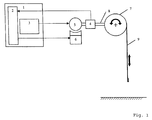
- FIG. 1 shows a schematic view of a door installation with a rolling door and an electromechanical brake.
- FIG. 2 shows a schematic view of a door installation with a balancing device.
- a door controller 1 which includes a frequency converter 3 and a control device 2 , is depicted in FIG. 1 .
- the frequency converter 3 receives from the control device 2 an input for the frequency and rotational direction that are to be outputted and with which an electrical power unit 5 can be fed, which is mechanically connected with a door shaft 7 by means of a driveshaft 8 and on this path can set a door hanging 9 in motion.
- the control device 2 can constantly be informed of the actual position and speed of the door power unit 5 and of the door hanging 9 that is mechanically coupled with it by means of a position sensor 4 , which can be positioned between the electrical power unit 5 and the door shaft 7 or on or at the door shaft 7 or can be integrated in the electrical power unit 5 or positioned at another point, and which can take the form of an absolute value indicator or an incremental indicator.
- the inventive control device 2 is a component of the door controller 1 and is depicted only in schematic form, because it is combined as a software module in the logical pathways.
- the control device 2 in any case is contained in the door controller 1 and according to the invention only assumes additional tasks.
- the inventive control device 2 processes the current nominal values for “rotational direction” and “travel speed” that are present internally and compares them with the actual values of the data provided by the position sensor 4 , from which the rotational direction and the momentary speed of the gate power unit, in addition to the instantaneous door position, can be ascertained.
- the control device 2 detects a difference that lies outside a previously defined range, then the control device 2 operates the frequency converter 3 and gives the frequency converter 3 a frequency input of 0 Hertz (Hz) in order to drastically reduce the speed of the electrical power unit 5 or to bring it to a stop.
- the inventive control device 2 operates a braking device 6 so that this device can support the braking process.
- This braking device 6 is configured as an electromechanical braking device.
- the inventive method can also be applied to monitor the functioning of the power unit 5 .
- the power unit 5 for instance because of mechanical ware of the door hanging 9 , cannot be moved or held in the required manner, at any time the braking device 6 can be powered by the inventive control device 2 in order to brake the door hanging 9 .
- a balancing device 10 is configured as a counterweight, which is suspended by a cable and whose mass corresponds approximately to the mass of the door hanging 9 .
- the balancing device 10 should be defective, for instance because of a worm cable, the door hanging 9 would move downward more or less unbraked.
- the control device 2 In comparing the nominal values with the actual values, if the control device 2 detects an unintended motion of the door, which lies outside a previously defined range, the control device 2 gives the frequency converter 3 a frequency input of 0 Hertz (Hz) in order to drastically reduce or bring to a standstill the speed of the electrical power unit 5 .
- Hz Hertz
- the electrical power unit is not of such dimension, as a rule, that it can hold the full load of a defective door mechanism.
- the control device 2 after detecting a defect, moves the door in slow motion into a safe resting position, which for instance can be the closed position of the door, which depends on the type of door, but can also be a different position.
Abstract
Description
Claims (13)
Applications Claiming Priority (3)
| Application Number | Priority Date | Filing Date | Title |
|---|---|---|---|
| DE102006034962 | 2006-07-28 | ||
| DE102006034962.8 | 2006-07-28 | ||
| DE102006034962A DE102006034962B4 (en) | 2006-07-28 | 2006-07-28 | Method for secure braking of a gate and device for carrying out the method |
Publications (2)
| Publication Number | Publication Date |
|---|---|
| US20080036409A1 US20080036409A1 (en) | 2008-02-14 |
| US7723936B2 true US7723936B2 (en) | 2010-05-25 |
Family
ID=38610850
Family Applications (1)
| Application Number | Title | Priority Date | Filing Date |
|---|---|---|---|
| US11/829,355 Active 2028-06-25 US7723936B2 (en) | 2006-07-28 | 2007-07-27 | Method for controlled braking of a door and device for applying said method |
Country Status (4)
| Country | Link |
|---|---|
| US (1) | US7723936B2 (en) |
| EP (1) | EP1882802B1 (en) |
| DE (1) | DE102006034962B4 (en) |
| DK (1) | DK1882802T3 (en) |
Cited By (7)
| Publication number | Priority date | Publication date | Assignee | Title |
|---|---|---|---|---|
| US20150176321A1 (en) * | 2013-12-23 | 2015-06-25 | Gabrijel Rejc Gmbh & Co. Kg | Drive and control system for lifting gates |
| WO2016095536A1 (en) * | 2014-12-17 | 2016-06-23 | 邹家春 | Power-losing trigger device |
| US20170226788A1 (en) * | 2014-04-02 | 2017-08-10 | Ford Global Technologies, Llc | Vehicle closure member power actuator control |
| US10829989B2 (en) | 2016-06-28 | 2020-11-10 | Gabrijel Rejc | Motor-operable and vertically movable gate |
| US10914117B2 (en) | 2016-06-28 | 2021-02-09 | Gabrijel Rejc | Vertically movable gate with a gate panel |
| US11142939B2 (en) | 2019-12-13 | 2021-10-12 | Schlage Lock Company Llc | Power boost module |
| US11499369B2 (en) * | 2016-12-15 | 2022-11-15 | Gabrijel Rejc Gmbh & Co. Kg | Gate with a crash-down prevention mechanism and method for triggering the crash-down prevention mechanism |
Families Citing this family (7)
| Publication number | Priority date | Publication date | Assignee | Title |
|---|---|---|---|---|
| DE102009008132B4 (en) * | 2009-02-09 | 2011-09-15 | Feig Electronic Gmbh | Gate control for controlling a motor driven gate |
| DE102011107866A1 (en) * | 2011-07-18 | 2013-01-24 | Novoferm Tormatic Gmbh | Method for operating a building closure |
| JP6235920B2 (en) * | 2014-01-31 | 2017-11-22 | 三和シヤッター工業株式会社 | Abnormality judgment device of position detection sensor in electric shutter for building |
| DE102016207029A1 (en) * | 2016-04-26 | 2017-10-26 | Geze Gmbh | Drive unit and method for closing a wing of a door or a window |
| CN110139962A (en) * | 2016-12-22 | 2019-08-16 | 百立富设计与工程私营有限公司 | Pull-down flood defence barrier |
| DE102021114570A1 (en) | 2021-04-22 | 2022-10-27 | Hörmann KG Antriebstechnik | Method of operation, control and building or enclosure closure drive device with frequency converter |
| DE102022119074A1 (en) | 2022-07-29 | 2024-02-01 | Feig Electronic Gmbh | Drive device for moving a darkening, adjusting or closing device |
Citations (17)
| Publication number | Priority date | Publication date | Assignee | Title |
|---|---|---|---|---|
| DE1701251U (en) | 1954-03-12 | 1955-06-23 | Siemens Ag | CERAMIC ISOLATOR (BONE INSULATOR) FOR SUSPENSION, PREFERABLY FROM BONE WIRES. |
| US4698622A (en) * | 1984-04-16 | 1987-10-06 | Daihatsu Diesel Mfg. Co., Ltd. | Brake apparatus for automatic door |
| DE3701251A1 (en) | 1987-01-17 | 1988-07-28 | Menke Wilhelm | COLLAR DEVICE FOR ROLLING DOORS WITH CLAMP RING |
| DE3814275A1 (en) | 1987-04-28 | 1988-12-01 | Novoferm Stahlbauwerk Neumayer | Fall brake |
| US4999551A (en) * | 1989-08-17 | 1991-03-12 | Yoshida Kogyo K.K. | Method for controlling opening/closing of door in automatic door system |
| EP0429835A1 (en) | 1989-11-27 | 1991-06-05 | Inventio Ag | Method and arrangement to decrease the risk of being caught between automatic doors |
| DE4138711A1 (en) | 1991-11-20 | 1993-05-27 | Dancho Zochev Dipl Ing Donkov | Protection device against falling for lifting doors - has door plate located in guide profiles on both sides, and with catchment device on lower edge |
| DE29513962U1 (en) | 1995-08-31 | 1995-10-19 | Feig Electronic Gmbh | Control device for power operated doors, gates and barriers |
| US5512883A (en) * | 1992-11-03 | 1996-04-30 | Lane, Jr.; William E. | Method and device for monitoring the operation of a motor |
| EP0841743A2 (en) | 1996-11-07 | 1998-05-13 | R. Stahl Fördertechnik GmbH | Control device for an emergency stop |
| US5831403A (en) * | 1996-02-28 | 1998-11-03 | Nabco Limited | Controller for an automatic door system |
| DE19855697A1 (en) | 1998-07-27 | 2000-02-10 | Hoermann Kg | Spring break protection |
| US6078263A (en) * | 1996-02-20 | 2000-06-20 | Rs Parts Distributors, Inc. | Method and apparatus for ensuring safe operation of electric overhead door |
| US6388412B1 (en) * | 2000-05-09 | 2002-05-14 | Overhead Door Corporation | Door operator control system and method |
| US6445152B1 (en) | 1999-11-24 | 2002-09-03 | Westinghouse Air Brake Co. | Door control system |
| DE10142431A1 (en) | 2001-08-31 | 2003-04-03 | Feig Electronic Gmbh | Controller for high speed gate, generates demand value for output frequency from absolute position sensor data and force-time profiles stored in control unit and controls gate movement |
| FR2868112A1 (en) | 2004-03-24 | 2005-09-30 | Meridionale Des Clotures Et Me | Casement opening, closing and locking device for portal located at entry of residence, has reducer to transmit mechanical torque between output shaft of motor and casement, and brake to lock casement in closed/open position |
Family Cites Families (1)
| Publication number | Priority date | Publication date | Assignee | Title |
|---|---|---|---|---|
| DE4207705C1 (en) * | 1992-03-11 | 1993-04-29 | Dorma Gmbh + Co. Kg, 5828 Ennepetal, De |
-
2006
- 2006-07-28 DE DE102006034962A patent/DE102006034962B4/en not_active Withdrawn - After Issue
-
2007
- 2007-07-03 EP EP07111601.6A patent/EP1882802B1/en active Active
- 2007-07-03 DK DK07111601.6T patent/DK1882802T3/en active
- 2007-07-27 US US11/829,355 patent/US7723936B2/en active Active
Patent Citations (19)
| Publication number | Priority date | Publication date | Assignee | Title |
|---|---|---|---|---|
| DE1701251U (en) | 1954-03-12 | 1955-06-23 | Siemens Ag | CERAMIC ISOLATOR (BONE INSULATOR) FOR SUSPENSION, PREFERABLY FROM BONE WIRES. |
| US4698622A (en) * | 1984-04-16 | 1987-10-06 | Daihatsu Diesel Mfg. Co., Ltd. | Brake apparatus for automatic door |
| DE3701251A1 (en) | 1987-01-17 | 1988-07-28 | Menke Wilhelm | COLLAR DEVICE FOR ROLLING DOORS WITH CLAMP RING |
| DE3814275A1 (en) | 1987-04-28 | 1988-12-01 | Novoferm Stahlbauwerk Neumayer | Fall brake |
| US4999551A (en) * | 1989-08-17 | 1991-03-12 | Yoshida Kogyo K.K. | Method for controlling opening/closing of door in automatic door system |
| EP0429835A1 (en) | 1989-11-27 | 1991-06-05 | Inventio Ag | Method and arrangement to decrease the risk of being caught between automatic doors |
| DE4138711A1 (en) | 1991-11-20 | 1993-05-27 | Dancho Zochev Dipl Ing Donkov | Protection device against falling for lifting doors - has door plate located in guide profiles on both sides, and with catchment device on lower edge |
| US5512883A (en) * | 1992-11-03 | 1996-04-30 | Lane, Jr.; William E. | Method and device for monitoring the operation of a motor |
| DE29513962U1 (en) | 1995-08-31 | 1995-10-19 | Feig Electronic Gmbh | Control device for power operated doors, gates and barriers |
| US6078263A (en) * | 1996-02-20 | 2000-06-20 | Rs Parts Distributors, Inc. | Method and apparatus for ensuring safe operation of electric overhead door |
| US5831403A (en) * | 1996-02-28 | 1998-11-03 | Nabco Limited | Controller for an automatic door system |
| EP0841743A2 (en) | 1996-11-07 | 1998-05-13 | R. Stahl Fördertechnik GmbH | Control device for an emergency stop |
| DE19645811A1 (en) | 1996-11-07 | 1998-06-04 | Stahl R Foerdertech Gmbh | Control arrangement for emergency shutdown |
| DE19855697A1 (en) | 1998-07-27 | 2000-02-10 | Hoermann Kg | Spring break protection |
| US6445152B1 (en) | 1999-11-24 | 2002-09-03 | Westinghouse Air Brake Co. | Door control system |
| US6388412B1 (en) * | 2000-05-09 | 2002-05-14 | Overhead Door Corporation | Door operator control system and method |
| US6737823B2 (en) * | 2000-05-09 | 2004-05-18 | Overhead Door Corporation | Door operator control system and method |
| DE10142431A1 (en) | 2001-08-31 | 2003-04-03 | Feig Electronic Gmbh | Controller for high speed gate, generates demand value for output frequency from absolute position sensor data and force-time profiles stored in control unit and controls gate movement |
| FR2868112A1 (en) | 2004-03-24 | 2005-09-30 | Meridionale Des Clotures Et Me | Casement opening, closing and locking device for portal located at entry of residence, has reducer to transmit mechanical torque between output shaft of motor and casement, and brake to lock casement in closed/open position |
Non-Patent Citations (1)
| Title |
|---|
| European Search Report; EP 07 11 1601; Jun. 11, 2009; 9 pages. |
Cited By (11)
| Publication number | Priority date | Publication date | Assignee | Title |
|---|---|---|---|---|
| US20150176321A1 (en) * | 2013-12-23 | 2015-06-25 | Gabrijel Rejc Gmbh & Co. Kg | Drive and control system for lifting gates |
| US9416579B2 (en) * | 2013-12-23 | 2016-08-16 | Gabrijel Rejc Gmbh & Co. Kg | Drive and control system for lifting gates |
| US20170226788A1 (en) * | 2014-04-02 | 2017-08-10 | Ford Global Technologies, Llc | Vehicle closure member power actuator control |
| US10415295B2 (en) * | 2014-04-02 | 2019-09-17 | Ford Global Technologies, Llc | Vehicle closure member power actuator control |
| WO2016095536A1 (en) * | 2014-12-17 | 2016-06-23 | 邹家春 | Power-losing trigger device |
| US10144614B2 (en) | 2014-12-17 | 2018-12-04 | Hangzhou Huning Elevator Parts Co., Ltd. | Power-loss triggering device |
| US10829989B2 (en) | 2016-06-28 | 2020-11-10 | Gabrijel Rejc | Motor-operable and vertically movable gate |
| US10914117B2 (en) | 2016-06-28 | 2021-02-09 | Gabrijel Rejc | Vertically movable gate with a gate panel |
| US11499369B2 (en) * | 2016-12-15 | 2022-11-15 | Gabrijel Rejc Gmbh & Co. Kg | Gate with a crash-down prevention mechanism and method for triggering the crash-down prevention mechanism |
| US11142939B2 (en) | 2019-12-13 | 2021-10-12 | Schlage Lock Company Llc | Power boost module |
| US11846133B2 (en) | 2019-12-13 | 2023-12-19 | Schlage Lock Company Llc | Power boost module |
Also Published As
| Publication number | Publication date |
|---|---|
| EP1882802A2 (en) | 2008-01-30 |
| DE102006034962A1 (en) | 2008-01-31 |
| DE102006034962B4 (en) | 2010-07-08 |
| EP1882802A3 (en) | 2009-07-22 |
| US20080036409A1 (en) | 2008-02-14 |
| DK1882802T3 (en) | 2016-09-26 |
| EP1882802B1 (en) | 2016-08-10 |
Similar Documents
| Publication | Publication Date | Title |
|---|---|---|
| US7723936B2 (en) | Method for controlled braking of a door and device for applying said method | |
| US7730998B2 (en) | Elevator apparatus | |
| EP2682360B1 (en) | Elevator system | |
| EP2049427B1 (en) | Method and system for detecting and stopping uncontrolled movement of an elevator car in an elevator | |
| EP2048104B1 (en) | Elevator device | |
| CN101243000B (en) | Elevator system | |
| US9416579B2 (en) | Drive and control system for lifting gates | |
| US8997941B2 (en) | Elevator safety circuit with safety relay delay | |
| US8813919B2 (en) | Elevator safety system preventing collision of cars | |
| US7891466B2 (en) | Elevator apparatus for emergency braking | |
| US7819229B2 (en) | Elevator safety system | |
| JP5816102B2 (en) | Electronic safety elevator | |
| EP2774886B1 (en) | Traction sheave elevator | |
| BRPI0415943B1 (en) | LIFT SAFETY DEVICE | |
| EP1997764A1 (en) | Elevator device | |
| JP2011046493A (en) | Safety device of elevator | |
| US6078263A (en) | Method and apparatus for ensuring safe operation of electric overhead door | |
| JP2011121742A (en) | Elevator braking device | |
| WO2005105648A1 (en) | Elevator apparatus | |
| KR100727198B1 (en) | Elevator apparatus | |
| JPS6128592B2 (en) |
Legal Events
| Date | Code | Title | Description |
|---|---|---|---|
| AS | Assignment |
Owner name: FEIG ELECTRONIC GMBH, GERMANY Free format text: ASSIGNMENT OF ASSIGNORS INTEREST;ASSIGNOR:SCHAEFER, DIRK;REEL/FRAME:019645/0938 Effective date: 20070710 Owner name: FEIG ELECTRONIC GMBH,GERMANY Free format text: ASSIGNMENT OF ASSIGNORS INTEREST;ASSIGNOR:SCHAEFER, DIRK;REEL/FRAME:019645/0938 Effective date: 20070710 |
|
| STCF | Information on status: patent grant |
Free format text: PATENTED CASE |
|
| FEPP | Fee payment procedure |
Free format text: PAYOR NUMBER ASSIGNED (ORIGINAL EVENT CODE: ASPN); ENTITY STATUS OF PATENT OWNER: LARGE ENTITY |
|
| FPAY | Fee payment |
Year of fee payment: 4 |
|
| MAFP | Maintenance fee payment |
Free format text: PAYMENT OF MAINTENANCE FEE, 8TH YEAR, LARGE ENTITY (ORIGINAL EVENT CODE: M1552) Year of fee payment: 8 |
|
| MAFP | Maintenance fee payment |
Free format text: PAYMENT OF MAINTENANCE FEE, 12TH YEAR, LARGE ENTITY (ORIGINAL EVENT CODE: M1553); ENTITY STATUS OF PATENT OWNER: LARGE ENTITY Year of fee payment: 12 |