US7722417B2 - Trolling motor mount with mono main arm - Google Patents
Trolling motor mount with mono main arm Download PDFInfo
- Publication number
- US7722417B2 US7722417B2 US12/074,389 US7438908A US7722417B2 US 7722417 B2 US7722417 B2 US 7722417B2 US 7438908 A US7438908 A US 7438908A US 7722417 B2 US7722417 B2 US 7722417B2
- Authority
- US
- United States
- Prior art keywords
- main arm
- base
- mount
- motor
- latch
- Prior art date
- Legal status (The legal status is an assumption and is not a legal conclusion. Google has not performed a legal analysis and makes no representation as to the accuracy of the status listed.)
- Active, expires
Links
Images


Classifications
-
- B—PERFORMING OPERATIONS; TRANSPORTING
- B63—SHIPS OR OTHER WATERBORNE VESSELS; RELATED EQUIPMENT
- B63H—MARINE PROPULSION OR STEERING
- B63H20/00—Outboard propulsion units, e.g. outboard motors or Z-drives; Arrangements thereof on vessels
- B63H20/08—Means enabling movement of the position of the propulsion element, e.g. for trim, tilt or steering; Control of trim or tilt
-
- B—PERFORMING OPERATIONS; TRANSPORTING
- B63—SHIPS OR OTHER WATERBORNE VESSELS; RELATED EQUIPMENT
- B63H—MARINE PROPULSION OR STEERING
- B63H20/00—Outboard propulsion units, e.g. outboard motors or Z-drives; Arrangements thereof on vessels
- B63H20/007—Trolling propulsion units
Definitions
- the present invention relates to trolling motors, and more particularly to a mounting device for securing a trolling motor to a watercraft.
- the trolling motor may be used to maneuver or to hold the watercraft in position while the vessel operator fishes.
- Trolling motors may be interconnected with the watercraft via a mount secured to the bow of the vessel.
- Convention bow mounts include a base plate and several movable arms, which are configured to retain the trolling motor and interlock with the base plate.
- the movable arms are generally configured to pivot between a stowed position, where the trolling motor is on-board the vessel, and a deployed operation position, where the trolling motor extends into the water.
- a mount for securing a trolling motor to a watercraft has a base, a main arm, a motor coupling, and a linkage.
- the motor coupling is configured to rotatably retain the trolling motor.
- the main arm is pivotally coupled to the base.
- the linkage is pivotally coupled with the base and the main arm and extends within the main arm to contact the motor coupling for actuating rotation of the motor coupling between a first position when the main arm is in a stowed position, and a second position when the main arm is in a deployed position.
- an apparatus for coupling a trolling motor to a mount includes a motor coupling assembly and a linkage assembly.
- the motor coupling assembly includes a sleeve configured to couple to the trolling motor.
- the linkage assembly is configured to interconnect to the mount.
- the motor coupling assembly and the linkage assembly have male and female interlocking surface profiles.
- FIG. 1A is a perspective view of an exemplary embodiment of a mount shown in a deployed position securing a trolling motor to the bow of a watercraft.
- FIG. 1B is a perspective view of the mount from FIG. 1A securing the trolling motor to the bow of a watercraft in a stowed position with base side plates removed.
- FIG. 2 is an exploded view of the mount from FIG. 1A , viewed from the rear.
- FIG. 3 is an exploded view of the base assembly from FIG. 2 , viewed from the front.
- FIG. 4A is a perspective view of the base extrusion from FIG. 2 , viewed from the front.
- FIG. 4B is a top view of the base extrusion from FIG. 4A .
- FIG. 4C is a side view of the base extrusion from FIG. 4A .
- FIG. 5A is a top view of the motor ramp from FIG. 2 .
- FIG. 5B is a side view of the motor ramp from FIG. 5A .
- FIG. 6 is an exploded view of the arm assembly from FIG. 2 , viewed from the front.
- FIG. 7A is a perspective view of the main arm from FIG. 2 , viewed from the front.
- FIG. 7B is a side view of the main arm from FIG. 7A .
- FIG. 7C is a bottom view of the main arm from FIG. 7A .
- FIG. 7D is an front end view of the main arm from FIG. 7A .
- FIG. 8B is a side view of the yoke from FIG. 8A .
- FIG. 8C is a bottom view of the yoke from FIG. 8A .
- FIG. 8D is a front view of the yoke from FIG. 8A .
- FIG. 9A is a perspective view of the rear pivot bracket from FIG. 2 , viewed from the rear.
- FIG. 9B is a side view of the rear pivot bracket from FIG. 9A .
- FIG. 9C is a rear view of the rear pivot bracket from FIG. 9A .
- FIG. 10A is a side view of the rear pivot bushing from FIG. 2 .
- FIG. 10B is a sectional view of the rear pivot bushing from FIG. 10A .
- FIG. 11A is a side view of the leaf spring from FIG. 2 .
- FIG. 11B is a bottom view of the leaf spring from FIG. 11A .
- FIG. 12A is a perspective view of the rope guide from FIG. 2 , viewed from the side.
- FIG. 12B is a side sectional view of the rope guide from FIG. 12A .
- FIG. 13A is a side view of the safety latch from FIG. 2 .
- FIG. 13B is a front end view of the safety latch from FIG. 13A .
- FIG. 14A is a perspective view of the rear latch bracket from FIG. 2 , viewed from the front.
- FIG. 14B is a side view of the rear latch bracket from FIG. 14A .
- FIG. 15A is a perspective view of the latch strap bracket from FIG. 2 , viewed from the front.
- FIG. 15B is a top view of the latch strap bracket from FIG. 15A .
- FIG. 15C is a side view of the latch strap bracket from FIG. 15A .
- FIG. 16A is a perspective view of the latch bar from FIG. 2 , viewed from the top front.
- FIG. 16B is a perspective view of the latch bar from FIG. 16B , viewed from the bottom rear.
- FIG. 17A is a top view of the bias mechanism from FIG. 2 .
- FIG. 17B is a side view of the bias mechanism from FIG. 17A .
- FIG. 18 is an exploded view of the motor coupling assembly from FIG. 2 , viewed from the rear.
- FIG. 19 is a view of the mount from FIG. 1A with the motor coupling assembly, the washer, and the fastener removed from an interlocking position with the mount.
- FIG. 20 is a perspective view of the motor coupling assembly from FIG. 19 in an interlocking position with the linkage assembly from FIG. 19 , viewed from the rear.
- FIG. 21A is a perspective view of the mount from FIG. 1A with the main arm and the base assembly suppressed to show the linkage assembly, the motion control device, and the latch system, viewed from the side.
- FIG. 22 is an elevated perspective view of the mount from FIG. 1A , viewed from the rear.
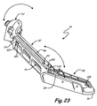
- FIG. 23 is a perspective view of the mount shown between the deployed position and the stowed position, viewed from the side.
- FIGS. 1A and 1B show an embodiment of a trolling motor assembly 10 , which is secured to the gunnels or other suitable surface(s) of a watercraft 12 .
- the trolling motor assembly 10 includes a rope 14 , a trolling motor 16 , and a mount 18 .
- the trolling motor 16 includes a head 20 , a shaft 22 , a propulsion unit 24 and a propeller 26 .
- the mount 18 includes a base assembly 28 , a main arm assembly 30 , and a motor coupling assembly 32 .
- the trolling motor assembly 10 is shown in the deployed position with the trolling motor 16 entering the water.
- the trolling motor assembly 10 is shown in the stowed position with the trolling motor 16 retained aboard the watercraft 12 , generally parallel with the gunnels of the watercraft 12 . In both positions, the trolling motor 16 is secured by the mount 18 to the watercraft 12 .
- the base assembly 28 secures the remainder of the mount 18 and the trolling motor 16 to the watercraft 12 .
- the rear of the main arm assembly 30 pivotally couples with the rear of the base assembly 28 .
- the front of the main arm assembly 28 pivotally couples with the motor coupling assembly 32 , which rotatably couples with the shaft 22 of the trolling motor 16 .
- the main arm assembly 30 is adapted to rotate relative to the base assembly 28 between the stowed position and the deployed position.
- the main arm assembly 30 is configured to releasably latch to the base assembly 28 in the stowed position and in the deployed position.
- the rope 14 enters the interior of the main arm assembly 30 and is used by the operator to unlatch the main arm assembly 30 from the base assembly 30 in the stowed position and in the deployed position. In another embodiment, the rope 14 is used to rotate the main arm assembly 30 between the stowed position and the deployed position. Simultaneous with the rotation of the main arm assembly 30 from the stowed position to the deployed position, the main arm assembly 30 is adapted to rotate the motor coupling assembly 32 from a first generally vertical position to a second generally horizontal position.
- the pivotal rotation of the motor coupling assembly 32 allows the trolling motor 16 to be disposed generally vertically in the water for operational use in deployed position, and allows the trolling motor 16 to be disposed generally horizontal to the gunnels for “non-use” in the stowed position.
- the trolling motor assembly 10 operates to control the velocity and direction of the watercraft 12 .
- the watercraft 12 may be any make, model, or size; and may be a recreational or commercial vessel.
- the propulsion unit 24 To drive the watercraft 12 , the propulsion unit 24 must be positioned below the surface of the water.
- the trolling motor 16 exerts mechanical propulsion by converting electrical current into thrust of the propeller 26 while the propulsion unit 24 is in the water.
- the shaft 22 is coupled with the mount 18 and the mount 18 is secured to a surface of the watercraft 12 .
- the interconnected components allow the propulsion unit 24 to transfer the thrust of the propeller 26 to the watercraft 12 .
- the trolling motor 16 (and watercraft 12 ) may be directionally controlled by the operator via a steering mechanism (such as a foot pedal or remote control) or by a handle on the head 20 .
- FIG. 2 shows an exploded view of an embodiment of the mount 18 , viewed from the rear.
- the base assembly 28 is comprised of a base extrusion 34 , a motor ramp 36 , side plate supports 38 , and side plates 40 .
- the base extrusion 34 includes a base plate 42 , and side walls 44 .
- the main arm assembly 30 includes a main arm 46 , a rear pivot mechanism 48 , a linkage assembly 50 , a latch system 52 , and a motion control device 54 .
- the main arm 46 is comprised of a bottom wall 56 , a top wall 58 , side walls 60 , rear pivot mechanism apertures 62 , and lower front apertures 64 .
- the rear pivot mechanism 48 includes a yoke 66 , rear pivot brackets 68 , rear pivot bushings 70 , a rear pivot pin 72 , and fasteners 74 .
- the linkage assembly 50 includes a leaf spring 76 , bushings 77 , a leaf spring stop 78 , an upper pin 80 , front side links 82 , linkage projections 84 , bushings 86 , a rope guide 88 , a rope hole 90 , a lower pin 92 , a torsion spring 94 , a safety latch 96 , and a washer 98 .
- the latch system 52 includes a rear latch assembly 100 , latch straps 101 , and a front latch assembly 102 .
- the rear latch assembly 100 includes a rear latch bracket 104 , a pivot pin 106 , e-clips 108 , and extension springs 110 .
- the front latch assembly 102 is comprised of a latch strap bracket 112 and a latch bar 114 .
- the motion control device 54 includes a bias mechanism 116 , a rear knurled pin 118 , a front pivot pin 120 , and fasteners 122 .
- the motor coupling assembly 32 includes an upper cover 124 , an upper bushing 126 , an upper sleeve 128 , a spring 130 , a lower sleeve 132 , a lower bushing 134 , a lower cover 136 and a fastener 138 .
- the upper cover 124 includes an orifice 140 , recesses 142 , and tracks 144 .
- the base assembly 28 extends symmetrically from a front portion to a rear portion, and is adapted to be secured to a surface.
- the rear portion of the base assembly 28 pivotally couples with the main arm 46 via the rear pivot mechanism 48 .
- the open frame rigid main arm 46 extends from a rear portion coupled to the base assembly 28 to a front portion.
- the linkage assembly 50 is disposed adjacent to (and is pivotally coupled with) the front portion of the main arm 46 , and extends through the main arm 46 to pivotally couple to the rear pivot mechanism 48 .
- the linkage assembly 50 and the motor coupling assembly 32 are adapted to removably interconnect.
- the latch system 52 is disposed inside the frame of the main arm 46 and interconnects to the rear portion of the main arm 46 .
- the latch system 52 extends within the main arm 46 from the rear portion to the front portion where it engages the linkage assembly 50 .
- the main arm 46 is adapted to allow the front portion of the latch system 52 to releasably engage the base assembly 28 in the deployed position, and is adapted to allow the rear portion of the latch system 52 to releasably engage the rear pivot mechanism 48 in the stowed position.
- the motion control device 54 is disposed within the frame of the main arm 46 , and pivotally couples with the main arm 46 and the rear pivot mechanism 48 .
- the main arm 46 cantilevers rearward from the rear portion of the base assembly 28 .
- the linkage assembly 50 holds the motor coupling assembly 32 in a generally vertical position so that the trolling motor 16 is disposed generally horizontal to the gunnels.
- the latch system 52 releasably engages the rear pivot mechanism 48 .
- the linkage assembly 50 actuates pivotal rotation of the motor coupling assembly 32 about the pivot coupling between the main arm 46 and the linkage assembly 50 .
- the linkage assembly 50 pivotally rotates the motor coupling assembly 32 from the generally vertical position when in the stowed position, to a generally horizontal position in the deployed position.
- the latch system 52 is actuated out of engagement with the base assembly 28 or the rear pivot mechanism 48 .
- the motion control device 54 assists, impedes, or biases the movement of the main arm 46 between the stowed position and the deployed position.
- the motion control device 54 actuates rotation of a portion of the rear pivot mechanism 48 .
- the main arm 46 In the deployed position, the main arm 46 is received in the U-shaped channel of the base assembly 28 .
- the linkage assembly 50 holds the motor coupling assembly 32 in a generally horizontal position.
- the latch system 52 releasably engages the front portion of the base assembly 28 .
- the base extrusion 34 is a U-shaped channel adapted to be secured to the surface(s) of the watercraft 12 .
- the motor ramp 36 is spade shaped interconnects to the front portion of the base extrusion 34 in a cantilevered fashion.
- the sides of the base extrusion 34 are adapted to secure to the side plate supports 38 and side plates 40 , which extend along the sides of the base extrusion 34 from the front to the rear.
- the side walls 44 of the base extrusion 34 extend generally vertically from the base plate 42 and are adapted to receive the main arm 46 between them when the main arm 46 is in the deployed position.
- the rear pivot mechanism 48 secures to the rear portion of the side walls 44 .
- the bottom wall 56 , side walls 60 and top wall 60 interconnect to form the open frame of the main arm 46 .
- the walls 56 , 58 , 60 extend from the rear portion of the main arm 46 to the front portion.
- the rear portion of the side walls 60 are adapted to extend further rearward than the bottom wall 56 or the top wall 60 .
- This cantilevered rear portion is adapted with rear pivot mechanism apertures 62 , which allow the main arm 46 to rotatably receive the rear pivot mechanism 48 .
- the lower front apertures 64 rotatably receive the linkage assembly 50 .
- FIG. 2 shows the major components of the rear pivot mechanism 48 including the yoke 66 .
- the yoke 66 is symmetrically disposed between the side walls 44 toward the rear portion of the base extrusion 34 .
- the yoke 66 couples with the motion control device 54 .
- the yoke 66 is adapted to receive a hub portion of the rear pivot brackets 68 and to pivotally rotate on this portion.
- the rear pivot bushings 70 interface with the rear pivot brackets 68 and with the edge of the rear pivot apertures 62 .
- the rear pivot brackets 68 have triangular rearward projections adapted to receive the rear pivot pin 72 .
- the fasteners 74 fix the rear pivot brackets 68 to the side walls 44 of the base extrusion 34 .
- the leaf spring 76 is adapted to receive the bushings 77 , which pivotally couple the leaf spring 76 to the rear pivot pin 72 .
- the leaf spring 76 extends through the interior of the main arm 46 from the rear end to the front end. In one embodiment, the central portion of the leaf spring 76 engages the leaf spring stop 78 when the main arm 46 is in the stowed position.
- the front portion of the leaf spring 76 is adapted to receive the bushings 77 , which pivotally couple the leaf spring 76 to the upper pin 80 .
- the ends of the upper pin 80 extend into the front side links 82 .
- the linkage projections 84 on the outer side surface of the front side links 82 are adapted to interface and connect the motor coupling assembly 32 to the linkage assembly 50 .
- the bushings 86 receive the upper pin 80 and space the front side links 82 from the rope guide 88 .
- the rope guide 88 rotatably mounts to the upper pin 80 to either side of the leaf spring 76 and is adapted to receive the rope 14 via the rope hole 90 .
- the front side links 82 and the rope guide 88 extend downward and forward to interconnect to the lower pin 92 .
- the lower pin 92 is received by the lower front apertures 64 of the main arm 46 .
- the lower pin 92 pivotally couples the linkage assembly 50 to the main arm 46 .
- the torsion spring 94 , safety latch 96 and washer 98 are configured to receive the lower pin 92 .
- the torsion spring 94 is configured to engage the lower portion of the rope guide 88 and the safety latch 96 .
- the latch system 52 is disposed within the main arm 46 .
- the rear latch assembly 100 is disposed toward the rear portion of the main arm 46 .
- the rear latch assembly 100 pivotally interconnects with the latch straps 101 , which extend forward to pivotally interconnect with the front latch assembly 102 . More specifically, the upper portion of the rear latch bracket 104 pivotally couples with the latch straps 101 .
- the lower portion the rear latch bracket 104 pivotally couples to the main arm 46 via the pivot pin 106 .
- the e-clips 108 are disposed on the pivot pin 106 interfacing the rear latch bracket 104 .
- the springs 110 interconnect the latch bracket 104 to the bottom surface 56 of the main arm 46 .
- the latch straps 101 pivotally couple to the latch strap bracket 112 .
- the latch strap bracket 112 is configured to slottedly receive the lower pin 92 at the front portion of the main arm 46 .
- the latch strap bracket 112 is adapted to receive the rope 14 , which enters the front interior portion of the main arm 46 through the rope hole 90 in the rope guide 88 .
- the latch strap bracket 112 is adapted to securely receive and interconnect with the latch bar 114 , which extends symmetrically through the latch strap bracket 112 and the side walls 60 to releasably engage the front portion of the base extrusion 34 when the main arm 46 is in the deployed position.
- FIG. 2 illustrates the major components of the motion control device 40 including the bias mechanism 116 , which extends into the main arm 46 from the rear.
- the rear and front portions of the bias mechanism 116 are adapted to pivotally couple with the rear knurled pin 118 and the front pivot pin 120 .
- the rear knurled pin 118 couples the bias mechanism 116 to the yoke 66 .
- the front pivot pin 120 extends generally horizontally between the side walls 60 of the main arm 46 and couples the bias mechanism 116 to the main arm 46 .
- the ends of the front pivot pin 120 may be treaded to securely receive fasteners 122 , which extend through the side walls 60 .
- the upper cover 124 extends over and interfaces with the upper bushing 126 , and extends around and over a portion of the upper sleeve 128 .
- the upper sleeve 128 rotatably interfaces with the upper bushing 126 and the spring 130 .
- the spring 130 interfaces with the lower sleeve 132 .
- the lower sleeve 132 rotatably interfaces with the spring 130 and the lower bushing 134 and extends through the lower cover 136 .
- the lower cover 136 interconnects with the upper cover 124 .
- the fastener 138 removably secures the motor coupling assembly 32 to the linkage assembly 50 .
- the sleeves 128 , 132 may be adapted to rotatably interface with and couple to the shaft 22 of the trolling motor 16 , which is inserted into the interior of the motor coupling assembly 32 through an orifice 140 in the upper cover 124 .
- the upper cover 124 may include the recesses 142 and/or the tracks 144 , which are adapted to interface with and secure the motor coupling assembly 32 to the front side links 82 .
- FIG. 3 shows an exploded front perspective view of an embodiment the base assembly 28 , which includes the base extrusion 34 , the motor ramp 36 , the side plate supports 38 , and the side plates 40 . Additionally, the base assembly 28 includes motor ramp fasteners 146 , side plate support fasteners 148 , and side plate fasteners 150 .
- the base extrusion 34 is a U-shaped channel adapted to be secured to surface(s) such as the gunnels.
- the motor ramp fasteners 146 secure the motor ramp 36 to the lower front portion of the base extrusion 34 .
- the side walls 44 run along the length of the base extrusion 34 .
- the side walls 44 are adapted to receive the side plate support fasteners 148 , which mount the side plate supports 38 to the side walls 44 .
- the side plate supports 38 are adapted to receive the side plate fasteners 150 , which mount the side plates 40 to the side plate supports 38 .
- the side plates 40 cover the side surfaces of the base extrusion 34 for cosmetic purposes.
- FIGS. 4A to 4C show different views of an embodiment of the base extrusion 34 .
- the base extrusion 34 includes side plate support apertures 152 , pivot mechanism apertures 154 , slots 156 , front edges 157 , locking notches 158 , thru holes 160 , and motor ramp apertures 162 .
- FIGS. 4A to 4C show the two spaced apart side walls 44 that extend generally vertically upward from the base plate 42 and extend generally parallel to one another along the edge of the base plate 42 .
- the side walls 44 define a recess capable of receiving the main arm 46 in the deployed position.
- the side walls 44 are configured with side plate support apertures 152 to receive the side plate support fasteners 148 , which mount the side plate supports 38 to the side walls 44 .
- the countersunk pivot mechanism apertures 154 in the rear portion of the side walls 44 receive the fasteners 74 , which secure the rear pivot brackets 68 to the base extrusion 34 .
- the slots 156 are configured to receive a projecting portion of the rear pivot brackets 68 .
- the slots 156 retain the rear pivot brackets 68 from pivotally rotating.
- each locking notch 158 is disposed at a 7.5 degree angle to the base plate 42 .
- the lower edge of each locking notch 158 extends forward past the forward termination point of the front edges 157 .
- the lower edges of the locking notches 158 are configured to catch the latch bar 114 .
- the angle of the locking notches 158 draws the latch bar 114 into releasable engagement with the locking notches 158 when the main arm 46 is in the deployed position.
- means including apertures, recesses, tabs, or slots may be used to engage the main arm 46 with the base assembly 28 .
- the base plate 42 is generally flat for ease of mounting, and rectangular in shape.
- the base plate 42 extends from a rear end generally near the rear pivot mechanism 48 to a front end, which interconnects with the motor ramp 36 .
- the base plate 42 is configured with thru holes 160 , which receive fasteners that secure the trolling motor assembly 10 to the surface of the watercraft 12 .
- the motor ramp apertures 162 extend through the base plate 42 and receive the motor ramp fasteners 146 , which secure the motor ramp 36 to the base plate 42 .
- FIGS. 5A and 5B show an embodiment of the motor ramp 36 , which includes a base interconnection portion 164 , apertures 166 and a motor engaging portion 168 .
- the base interconnection portion 164 of the motor ramp 36 is adapted to be inserted on the front portion of the base plate 42 between the side walls 44 .
- the base interconnection portion 164 has apertures 166 , which align with the motor ramp apertures 162 when the motor ramp 36 is disposed on the base plate 42 .
- the motor ramp apertures 162 and the apertures 166 receive the motor ramp fasteners 146 , which secure the motor ramp 36 to the base plate 42 .
- the motor engaging portion 168 cantilevers off the front end of the base plate 42 and over the edge of the watercraft 12 . In FIGS.
- the motor engaging portion 168 is spade shaped with two angled surfaces connecting at one forward end point.
- the motor engaging portion 168 is adapted to rotate the propulsion unit 24 of the trolling motor 16 as the unit 24 comes into contact with the motor ramp 36 at a position between stow and deploy.
- the motor ramp 36 reduces the likelihood of contact between the propulsion unit 24 and the watercraft 12 .
- FIG. 6 is an exploded front perspective view of an embodiment of the main arm assembly 30 , which includes the main arm 46 , the rear pivot mechanism 48 , the linkage assembly 50 , the latch system 52 and the motion control device 54 .
- FIGS. 7A to 7D show different views of an embodiment of the main arm 46 .
- the main arm 46 includes a lower cutaway 170 , spring apertures 172 , a stop aperture 174 , a safety latch slot 176 , stop portions 178 , front latch slots 180 , latch thru holes 182 , motion control device thru holes 184 , and cutouts 186 .
- the main arm 46 is a single piece extrusion with a rigid open frame comprised of four interconnected walls.
- the main arm 46 is formed of a metallic such as aluminum.
- the main arm 46 is capable of housing most of the other components of the main arm assembly 36 .
- the bottom wall 56 is disposed below the top wall 58 when the main arm 46 is in the deployed position.
- the bottom wall 56 is generally rectangular and extends from a rear end adjacent the rear pivot mechanism 48 to a front end adjacent the motor coupling assembly 32 .
- the bottom wall 56 has a number of apertures.
- the generally square shaped lower cutaway 170 extends through the rear portion of the bottom wall 56 and receives the yoke 66 .
- the rear portion of the bottom wall 56 extends to either side of the lower cutaway 170 and has spring apertures 172 , which receive the extension springs 110 .
- the extension springs 110 connect the rear latch assembly 100 to the main arm 46 .
- the threaded stop aperture 174 extends through the center middle portion of the bottom wall 56 .
- the stop aperture 174 receives a fastener, which secures the leaf spring stop 78 to the interior surface of the bottom wall 56 .
- the safety latch slot 176 extends into the front portion of the bottom wall 56 .
- the safety latch slot 176 is adapted to receive a portion of the safety latch 96 when the motor coupling assembly 32 is removed from the linkage assembly 50 .
- the bottom wall 56 interconnects with a pair of generally rectangular shaped side walls 60 .
- the side walls 60 extend generally perpendicularly from the bottom wall 56 .
- the side walls 60 extend from the rear of the main arm 46 to the front.
- the rear portion of the side walls 60 are cantilevered off the end of the bottom wall 56 and the top wall 58 .
- the cantilevered portion has the rear pivot mechanism apertures 62 , which receive the rear pivot bushings 70 and rear pivot brackets 68 .
- the rear pivot mechanism apertures 62 are between about 1 inch and about 4 inches (about 25.4 mm and about 101.6 mm) in diameter.
- the pivot mechanism apertures 62 allow the main arm 46 to pivotally rotate about the stationary rear pivot brackets 68 .
- the side walls 60 include features which allow the main arm 46 to couple with the linkage assembly 50 , the front latch assembly 102 , and the motion control device 54 . More specifically, in one embodiment the stop portion 178 of the upper top front edge of the side walls 60 is adapted to abuttably interface with the upper pin 80 when the main arm 46 is in the deployed position.
- the front latch slot 180 in the lower front portion of the sidewalls 60 is adapted to receive the latch bar 114 , which extends through the front latch slot 180 from the interior of the main arm 46 .
- the front latch slot 180 allows the latch bar 114 to releasably slide into and out of engagement with the locking notch 158 when the main arm 46 is in the deployed position.
- the side walls 60 are configured with latch thru holes 182 and motion control device thru holes 184 , which receive pins 106 and 120 to pivotally couple the rear latch assembly 100 and the motion control device 54 to the main arm 46 , respectively.
- the latch thru holes 182 or motion control device thru holes 184 may be counter bored to receive the head of a fastener (such as fastener 122 ), which allows the fastener head to be generally flush with the exterior surface of the side walls 60 .
- the lower front portion of the side walls 60 are configured with the lower front apertures 64 to receive the lower pin 92 , which pivotally couples the linkage assembly 50 to the main arm. 46 .
- the side walls 60 have cutouts 186 separated by struts. The cutouts 186 allow the operator to view the interior components of the mount 18 , increase the cosmetic appeal of the mount 18 , and decrease the weight of the main arm 46 .
- the side-walls 60 interconnect with the top wall 58 .
- the top wall 58 is generally rectangular, and extends longitudinally from an end adjacent the rear pivot mechanism 48 to an end adjacent the motor coupling assembly 32 .
- the walls 50 , 52 , 54 surround and protect the interior components from damage during operation.
- the components that extend into or are located in the interior compartment 56 may include the leaf spring 76 , the rear latch assembly 100 , the front latch assembly 102 , and the motion control device 54 . In other embodiments of the invention, all or some of these components may be disposed outside the main arm 46 .
- FIG. 6 shows an exploded front perspective view of the rear pivot mechanism 48 , which includes the yoke 66 , the rear pivot brackets 68 , the rear pivot bushings 70 , the rear pivot pin 72 , and the fasteners 74 .
- the rear pivot mechanism 48 is secured between the side walls 44 at the rear portion of the base extrusion 46 and pivotally couples the main arm 46 to the base extrusion 46 .
- the rear pivot mechanism 48 also pivotally couples the leaf spring 76 to the base extrusion 46 .
- the rear pivot mechanism 48 allows the main arm 46 to be rotated approximately 177 degrees between the stowed position and the deployed position.
- the yoke 66 is symmetrically disposed between the side walls 60 toward the rear portion of the main arm 46 .
- the yoke 66 is configured with two symmetric hub receiving portions 186 having yoke pivot apertures 188 .
- the yoke pivot apertures 188 extend through the hub receiving portions 186 , and are adapted to rotatably receive a portion of the rear pivot brackets 68 .
- the yoke 66 is configured to allow the yoke pivot apertures 188 to align with the rear pivot apertures 62 when the main arm 46 is in the deployed position.
- the outer surfaces of two hub receiving portions 186 are adapted with channels 190 , which are capable of receiving the rear pivot bushings 70 .
- the base portion 192 of the yoke 66 contacts the base plate 42 when the main arm 46 is in the deployed position.
- the base portion 192 is adapted with two symmetric shaft receiving arms 194 , which contact the base plate 42 when the main arm 46 is in the deployed position.
- the shaft receiving arms 194 project generally vertically and are adapted to receive and retain the shaft 22 of the trolling motor 16 .
- the apertures 196 extend through the base portion 192 and receive the rear knurled pin 118 , which interconnects the yoke 66 with the motion control device 54 .
- the motion control device 54 actuates pivotal rotation of the yoke 66 about an axis defined by the rear pivot brackets 68 during a portion of the rotation of the main arm 46 between the stowed position and the deployed position. In one embodiment, this rotation occurs when the main arm 46 is between the stowed position and about 90 degrees.
- FIGS. 9A to 9C show an embodiment of the rear pivot brackets 68 , which include fins 198 , cylindrical hubs 200 , apertures 202 , keys 204 , rear apertures 206 , and retention apertures 208 .
- the circular projections 138 on the rear pivot brackets 68 are between about 1 inch in diameter and about 4 inches in diameter (about 25.4 mm and about 101.6 mm).
- the larger diameter of the pivot coupling (the typical mount utilizes pivot pin with a typical diameter of 0.25 inch or 0.50 inch (6.4 mm or 12.7 mm)) between the main arm 46 and the base assembly 28 increases the durability of the pivot coupling.
- the increased durability of the pivot coupling reduces the likelihood that the coupling may loosen and cause the mount 18 to rattle or make other unpleasant noises during operation of the watercraft 12 .
- the fins 198 may be configured to retain the rear pivot pin 72 non-pivotally or pivotally.
- the rear outward edge of the fin 198 is adapted with a threaded retention aperture 208 , which receives a fastener that engages the rear pivot pin 72 .
- the fastener retains the rear pivot pin 72 from pivotally rotating with the leaf spring 76 .
- the bushings 77 allow the leaf spring 76 to pivot on the stationary rear pivot pin 72 as the main arm 46 pivots on the rear pivot brackets 68 .
- FIGS. 10A and 10B show an embodiment of the rear pivot bushing 70 , which includes a lip 210 and an interior projection 212 .
- the split ring rear pivot bushings 70 are disposed in the rear pivot mechanism apertures 62 on the main arm 46 between the edge of the rear pivot mechanism apertures 62 and the cylindrical hubs 200 . More specifically, the annular lip 210 engages the outer surface of the side walls 60 . The interior projection 212 interfaces with the edge of the rear pivot mechanism apertures 62 and the annular cylindrical hubs 200 .
- the rear pivot bushing 70 allows the main arm 46 to be pivotally rotated relative to the stationary rear pivot bracket 68 .
- FIG. 6 shows an exploded front perspective view of the linkage assembly 50 , which includes the leaf spring 76 , the bushings 77 , the leaf spring stop 78 , the upper pin 80 , the front side links 82 , the linkage projections 84 , the bushings 86 , the rope guide 88 , the rope hole 90 , the lower pin 92 , the torsion spring 94 , the safety latch 96 , and the washer 98 .
- the linkage assembly 50 is disposed adjacent to (and pivotally couples with) the front portion of the main arm 46 , and extends through the main arm 46 to pivotally couple to the rear pivot mechanism 48 .
- the linkage assembly 50 and the motor coupling assembly 32 are adapted to removably interconnect.
- the rear portion 214 is adapted with the rear aperture 216 to receive the rear pivot pin 72 and the bushings 77 , which pivotally couple the leaf spring 76 to the rear pivot mechanism 48 .
- the member 218 interconnects with the rear portion 214 and extends through the open frame of the main arm 46 . In one embodiment, the member 218 may flexibly bow to contact the leaf spring stop 78 when the main arm 46 is in the stowed position.
- the front portion 220 interconnects with the member 218 and is adapted with the front aperture 222 to receive the upper pin 80 and the bushings 77 , which pivotally couple the leaf spring 76 to the remainder of the linkage assembly 50 .
- the leaf spring 76 actuates pivotal rotation of the remainder of the linkage assembly 50 (and the motor coupling assembly 32 ) about the pivot coupling between the main arm 46 and the linkage assembly 50 .
- the leaf spring 76 rotates the remainder of linkage assembly 50 (and the motor coupling assembly 32 ) from the generally vertical position when in the stowed position, to the generally horizontal position in the deployed position.
- FIG. 6 shows the front side links 82 , which include the linkage projections 84 .
- the two front side links 82 receive the ends of the upper pin 80 and extend downward and forward generally parallel to each other to receive the lower pin 92 .
- the longitudinally and vertically offset trapezoidal linkage projections 84 are adapted to receive the lower and upper pins 80 , 92 .
- the linkage projections 84 extend outwards from the exterior side surface of the front side links 82 .
- the linkage projections 84 are selectively sized and geometrically disposed to interlock with the recesses 142 on the motor coupling assembly 32 .
- FIGS. 12A and 12B show an embodiment of the rope guide 88 , which in addition to the rope hole 90 , includes an upper portion 224 , upper apertures 226 , lower members 228 , a motor coupling aperture 230 , and lower apertures 232 .
- the upper portion 224 of the rope guide 88 is separated from the front side links 82 along the length of the upper pin 80 by the bushings 86 .
- the upper apertures 226 pivotally receive the upper pin 80 .
- the upper portion 224 is disposed symmetrically over the front portion 220 and extends down to receive the upper pin 80 to either side of the front portion 220 of the leaf spring 76 .
- the rope hole 90 extends downward through the upper portion 224 .
- the rope hole 90 is adapted to receive the rope 14 .
- the upper portion 224 extends forward and interconnects with the lower members 228 .
- the two lower members 228 extend downward generally parallel to each other to receive the lower pin 92 .
- the threaded motor coupling aperture 230 receives the fastener 138 , which secures the motor coupling assembly 32 to the linkage assembly 50 .
- the lower apertures 232 receive the lower pin 92 , which allows the rope guide 88 to pivotally couple with the main arm 46 .
- FIGS. 13A and 13B show front and side views of an embodiment of the safety latch 96 , which includes a main body 234 , an aperture 236 , a rearward nose 238 , and a forward nose 240 .
- the safety latch 96 is disposed on the lower pin 92 adjacent one of the lower members 228 .
- the cylindrical main body 234 surrounds the lower pin 92 .
- the aperture 236 pivotally receives the lower pin 92 .
- the rearward nose 238 extends from the main body 234 and engages the torsion spring 94 .
- the forward nose 240 extends from the main body 234 and engages the motor coupling assembly 32 when the motor coupling assembly 32 is mounted on the linkage assembly 50 .
- the torsion spring 94 engages the adjacent lower member 228 to bias the rearward nose 238 into the safety latch slot 176 when the motor coupling assembly 32 is not interconnected with the linkage assembly 50 .
- FIG. 6 shows an exploded front perspective view of the latch system 52 , which includes the rear latch assembly 100 , the latch straps 101 , and the front latch assembly 102 .
- the rear latch assembly 100 includes the rear latch bracket 104 , the pivot pin 106 , the e-clips 108 , and the extension springs 110 .
- the front latch assembly 102 is comprised of the latch strap bracket 112 and the latch bar 114 .
- the latch system 52 is configured to releasably engage with the base extrusion 34 to lock the main arm 46 in the deployed position, and to releasably engage with the rear pivot mechanism 48 to lock the main arm 46 in the stowed position.
- the operator must actuate the latch system by pulling on the rope 14 before rotating the main arm 46 from either the stowed position or the deployed position.
- the latch system 100 protects against unintended and potentially harmful rotation of the main arm 46 .
- FIGS. 14A and 14B show an embodiment of the rear latch bracket 104 , which includes side surfaces 242 , a member 244 , a cutout 246 , spring apertures 248 , pivot apertures 250 , notches 252 , and upper apertures 254 .
- the rear latch bracket 104 has two symmetrical side surfaces 242 disposed generally parallel to each other.
- the side surfaces 242 are disposed adjacent the interior surface of the side walls 60 .
- the side surfaces 242 are interconnected by the member 244 .
- the half circular cutout 246 extends symmetrically through the lower portion of the member 244 . The cutout 246 accommodates the barrel of the bias mechanism 116 when the main arm 46 is in the deployed position.
- each side surface 242 receives the extension springs 110 , which connect the rear latch bracket 104 to the main arm 46 via the apertures 172 .
- the extension springs 110 bias the rear latch assembly 100 and the front latch assembly 102 into releasable engagement. To unlatch the rear latch assembly 100 and the front latch assembly 102 this bias must be overcome by the force of the operator's pull on the rope 14 .
- the extension springs 110 have an outside diameter of 0.375 inches (9.5 mm), a length of 1.25 inches (31.8 mm), and a spring rate of 30.26 pounds/inch (5.3 N/mm).
- the pivot apertures 250 are disposed through the lower rear of the side surfaces 242 and receive the pivot pin 106 , which pivotally couples the rear latch bracket 104 to the main arm 46 .
- the side surfaces 242 are contacted by the e-clips 108 , which retain the rear latch bracket 104 symmetrically on the pivot pin 106 .
- the notches 252 extend through rear edge side surfaces 242 and are configured to engage with the rear pivot pin 72 of the rear pivot mechanism 48 when the main arm 46 is in the stowed position.
- the notches 252 remain in engagement (biased by the extension springs 110 ) with the rear pivot pin 72 in the stowed position until the rear latch assembly 100 is pivotally actuated out of engagement by the operator.
- the upper apertures 254 receive fasteners, which pivotally couple the rear latch bracket 104 to the latch straps 101 .
- the latch straps 101 interconnect the rear latch bracket 104 with the latch strap bracket 112 (and the rear latch assembly 100 with the front latch assembly 102 ).
- the latch straps 101 are adapted to pivotally couple to both the rear latch bracket 104 and latch strap bracket 112 .
- both the rear latch assembly 100 and the front latch assembly 102 may be actuated simultaneously by the pull of the rope 14 .
- FIGS. 15A to 15C show an embodiment of the latch strap bracket 112 , which includes side walls 256 , a base platform 258 , thru holes 260 , square apertures 262 , slots 264 , an front wall 266 , a rope aperture 270 , and a groove projection 272 .
- the latch strap bracket 112 is disposed in the interior of the main arm 46 adjacent the front end of the main arm 46 .
- the symmetrical side walls 256 of latch strap bracket 112 interconnect generally vertically with the base platform 258 .
- Thru holes 260 receive the fasteners, which pivotally couple the latch straps 101 to the latch strap bracket 112 .
- the square apertures 262 are adapted to receive the latch bar 114 , which extends outward to either side of the side walls 256 .
- the slots 264 receive the lower pin 92 , which allows the latch system 52 to be slidably linearly actuated into and out of engagement with the base extrusion 34 or the rear pivot mechanism 48 .
- the front wall 266 interconnects to the side walls 256 .
- the rope aperture 270 extends through the front wall 266 and is adapted to receive the rope 14 , allowing the rope 14 to interconnect with the latch strap bracket 112 . This interconnection may occur, for example, by looping the rope 14 around the aperture 270 and then tying a knot, or by extending the rope 14 through the aperture 270 and then tying a knot that is larger than the rear side of the aperture 270 .
- the groove projection 272 extends generally vertically from the central portion of the base platform 258 generally parallel with the side walls 256 .
- the groove projection 272 generally aligns horizontally with the square apertures 262 .
- the groove projection 272 engages the latch bar 114 and retains the latch bar 114 from side-to-side movement.
- FIGS. 16A and 16B show an embodiment of the latch bar 114 , which includes a groove 274 and end portions 276 .
- the latch bar 114 is generally square in cross section, and in one embodiment is made of a polymer material, which reduces vibratory noise and can be cost effectively replaced after a period of use.
- the latch bar 114 extends through the latch strap bracket 112 from one side wall 256 to the other.
- the groove 274 extends across the center of the bottom surface of the latch bar 114 and engages the groove projection 272 .
- the end portions 276 of the latch bar 114 are rounded and extend from the side walls 256 through the slots 132 in the main arm 46 to engage the locking notches 158 in the base extrusion 34 when the main arm 46 is in the deployed position.
- the latch bar 114 remains in engagement (biased by the extension springs 110 ) with the locking notches 158 in the deployed position until the front latch assembly 102 is actuated by the operator.
- the operator By applying a pulling force to the rope 14 the operator causes the latch strap bracket 112 to slide forward moving the latch bar 114 out of engagement with the locking notches 158 .
- FIG. 6 shows an exploded front perspective view of the motion control device 54 , which includes the bias mechanism 116 , the rear knurled pin 118 , the front pivot pin 120 , and fasteners 122 .
- the motion control device 54 pivotally couples with the main arm 46 and extends within the main arm 46 to pivotally couple with the rear pivot mechanism 48 .
- the motion control device 54 may be configured to assist, impede, or otherwise bias the movement of the main arm 46 from the stowed position to the deployed position.
- the motion control device 54 is configured to assist the operator when the main arm 46 rotates through a part of its movement from the deployed position to the stowed position. In one embodiment, this assisting force is exerted by the motion control device 54 from the deployed position to about 90 degrees.
- the motion control device 54 is configured to impede the rotate of the main arm 46 through a part of its movement from the stowed position to the deployed position. In one embodiment, this impeding force is exerted by the motion control device 54 from about 90 degrees to the deployed position.
- the motion control device 54 may be configured to exert biasing forces (whether assisting or impeding) on the main arm 46 during other portions of the rotation path of the main arm 46 between the stowed position and the deployed position in other embodiments of the invention.
- FIGS. 17A and 17B show an embodiment of the bias mechanism 116 , which includes a rear portion 278 , a rear aperture 280 , a main body 282 , a front portion 284 , and a front aperture 286 .
- the rear portion 178 has the rear aperture 280 , which extends through it.
- the rear aperture 280 receives the rear knurled pin 118 , which allows the bias mechanism 116 to the pivotally couple with the rear pivot mechanism 48 .
- the main body 282 interconnects with the rear portion 278 , and in the embodiment shown is extendable and retractable from the rear portion 278 .
- the main body 282 is extendable and retractable only during a portion of the rotation of the main arm 46 between the stowed position and the deployed position.
- the bias mechanism 116 exerts its biasing force on the main arm 46 only during the extendable or retractable movement of the main body 282 .
- the main body 282 interconnects with the front portion 284 .
- the front aperture 286 extends through the front portion 284 .
- the front aperture 284 receives the front pivot pin 120 , which allows the bias mechanism 116 to pivotally couple with the main arm 46 .
- the front pivot pin 120 is fixed to the main arm 46 by the fasteners 122 .
- the bias mechanism 116 is a gas spring that provides assistance or resistance to the main arm 46 .
- the device 40 is a type of commercially available gas spring (Part No. 15F100260TT) from Engineered Components Products Hardware, LLC.
- the bias mechanism may be an air, an elastomer, a spring, a hydraulic device, or a mechanical device.
- FIG. 18 shows an embodiment of the motor coupling assembly 32 , which includes the upper cover 124 , the upper bushing 126 , the upper sleeve 128 , the spring 130 , the lower sleeve 132 , the lower bushing 134 , the lower cover 136 and the fastener 138 . Additionally, the lower cover 132 includes a second orifice 287 , and the upper cover 128 includes an aperture 288 .
- the motor coupling assembly 32 is removable from the linkage assembly 50 and the remainder of the mount 18 and is configured to couple with, retain, and guide the shaft 22 of the trolling motor 16 .
- the upper cover 124 extends over and interfaces with the upper bushing 126 , and extends around and over the lower portion of the upper sleeve 128 .
- the upper sleeve 128 rotatably interfaces against and aligns with the upper bushing 126 and the spring 130 .
- the upper sleeve 128 rotatably couples with the shaft 22 of the trolling motor 16 when the shaft 22 is inserted in the assembly 32 .
- the upper sleeve 128 may be configured to selectively tighten and loosen on the: shaft 22 .
- the spring 130 aligns with and interfaces against both the upper sleeve 128 and the lower sleeve 132 .
- the spring 130 protects and absorbs some of the shock incurred during operation of the trolling motor 16 .
- the lower sleeve 132 aligns with and rotatably interfaces against the spring 130 and the lower bushing 134 .
- the lower sleeve 132 rotatably couples with the shaft 22 of the trolling motor 16 .
- the lower sleeve 132 may be configured to selectively tighten and loosen on the shaft 22 .
- the lower cover 136 interconnects with and is fastened to the upper cover 124 to surround the interior components.
- the orifices 140 , 287 in the upper and lower covers 124 , 136 vertically align.
- the other components including the upper bushing 126 , the upper sleeve 128 , the spring 130 , the lower sleeve 132 , the lower bushing 134 also vertically align with the orifices 140 , 287 .
- the aligned components allow the second orifice 287 to receive the shaft 22 of the trolling motor 16 .
- the fastener 138 may be received by the aperture 288 , which aligns with the motor coupling aperture 230 . In one embodiment, the fastener 138 threads into the motor coupling aperture 230 to removably secure the motor coupling assembly 32 to the linkage assembly 50 .
- the upper cover 124 may include the recesses 142 and/or the tracks 144 adapted to interface with and mount the motor coupling assembly 32 to the front side links 82 .
- FIG. 19 shows the mount 18 and the features that allow the motor coupling assembly 32 to be removable from the linkage assembly 50 and the mount 18 .
- These features and components include the front side links 82 , the linkage projections 84 , the fastener 138 , the recesses. 142 and the tracks 144 . These features and components allow the motor coupling assembly 32 to be quickly disconnected from or connected to the linkage assembly 50 and the mount 18 .
- the motor coupling assembly 32 and trolling motor 16 can be quickly and easily disconnected from or connected to the mount 18 when compared with the conventional bow mount assembly. This is because in the conventional bow mount assembly the rope runs through the main arms to the motor coupling assembly. With the conventional configuration, therefore, the rope must be untied from the interior of the bow mount assembly's main arms before the motor coupling assembly and the trolling motor can be removed from the remainder of the mount.
- the linkage projections 84 are selectively sized to interlock with the recesses 142 .
- the linkage projections 84 and the recesses 142 interlock to retain the motor coupling assembly 32 from side-to-side or vertical motion when the motor coupling assembly 32 is interconnected to the linkage assembly 50 .
- the male and female interlocking surface profiles may be the only means of retaining the motor coupling assembly 32 and connecting the assembly 58 to the mount 18 .
- the male profile may be on the motor coupling assembly 32 and the female profile may be on the front side links 82 .
- the male/female interlocking profiles allow the operator to quickly remove or connect the motor coupling assembly 32 to or from the mount 18 .
- the tracks 144 guide the linkage projections 84 into interlocking contact with the recesses 142 as the motor coupling assembly 32 is moved downwards onto the front side links 82 .
- the process is reversed to remove the motor coupling assembly 32 from the front side links 82 .
- FIG. 19 shows the assembled rear pivot mechanism 48 disposed at the rear of the base assembly 28 and main arm assembly 30 .
- the main arm assembly 30 is shown in the deployed position.
- the base portion 192 of the yoke 66 contacts the base plate 42 .
- the yoke 66 is disposed symmetrically between the side walls 44 .
- the yoke 66 receives the cylindrical hubs 200 of the rear pivot bracket 68 .
- the yoke 66 is configured to pivotally rotate on the cylindrical hubs 200 of the rear pivot brackets 68 .
- the rear pivot bushings 70 interface the outer annular surface of the cylindrical hubs 200 and the circular edge of the rear pivot apertures 62 .
- the rear pivot bushings 70 allow the main arm 46 to pivot relative to the fixed rear pivot brackets 68 between the stowed position and the deployed position.
- the fasteners 74 (received by the pivot mechanism apertures 154 and threaded into the apertures 202 in rear pivot bracket 68 ) and slot projection 204 secure the rear pivot brackets 68 in a stationary position to the side walls 44 of the base extrusion 34 .
- the two rear pivot brackets 68 cantilever rearward off the rear end of the side walls 44 generally parallel to one another, and receive the rear pivot pin 72 .
- the rear portion 214 of the leaf spring 76 pivotally couples to the rear pivot pin 72 between the rear pivot brackets 68 .
- FIG. 19 shows the latch bar 114 extending from the side surfaces 60 of the main arm 46 to releasably engage the locking notches 158 . While the first arm 46 is in the deployed position the latch bar 114 remains in locked releasable engagement with the locking notches 158 until the operator actuates the latching system 52 forward by pulling on the rope 14 . As will be discussed in greater detail subsequently, while the motor coupling assembly 32 is removed from the linkage assembly 50 (as shown in FIG. 19 ) the latching system 52 cannot be actuated by the operator's pulling on the rope 14 . In FIG. 19 , the rope 14 enters the interior of the linkage assembly 50 via the rope hole 90 .
- the rope 14 is shown entering the interior of the linkage assembly 50 , which is engaged with the motor coupling assembly 32 .
- the rope 14 extends generally vertically downward between the lower members 228 of the rope guide 88 .
- the rope 14 wraps over the front facing portion of the lower pin 92 before entering the interior compartment of the main arm 46 to connect generally horizontally to the latch strap bracket 112 .
- FIG. 20 shows the “latch system lockout,” which includes the torsion spring 94 and safety latch 96 .
- the motor coupling assembly 32 is mounted on the linkage assembly 50
- the safety latch 96 is disposed on the lower pin 92 adjacent one of the lower members 228 .
- the rearward nose 238 of the safety latch 96 engages the torsion spring 94 and points generally rearward in a raised position.
- the forward nose 240 engages the motor coupling assembly. 32 and points generally forward.
- the torsion spring 94 engages the adjacent lower member 228 and the rearward nose 238 to bias the safety latch 96 .
- the safety latch 96 would rotate downward to dispose the rearward nose 238 in the safety latch slot 176 . While received in the safety latch slot 176 , the rearward nose 238 interferes with the sliding movement of the latch strap bracket 112 so that the main arm 46 cannot be unlatched from either the stowed position or the deployed position.
- FIG. 21A shows the components of the latching system 52 in the deployed position with the base assembly 28 and main arm 46 suppressed (i.e. not shown).
- the rope 14 generally horizontally interconnects with the latch strap bracket 112 .
- the slots 264 engage the lower pin 92 to transfer the pulling motion that the operator exerts on the rope 14 to a generally horizontal linear motion.
- the extension springs 110 bias the latch bar 114 into engagement with the locking notches 158 .
- FIG. 21B shows the components of the latching system 52 in the stowed position.
- the rear latch bracket 104 notches 252 engage the rear pivot pin 72 .
- the locking notches 98 remain in engagement (biased by the extension springs 110 ) with the rear pivot pin 72 in the stowed position until the rear latch assembly 100 is pivotally actuated out of engagement by the operator.
- the rear latch assembly 100 may be actuated out of engagement by a pull of the rope 14 ; which slides the front latch assembly 102 forward.
- the sliding motion of the front latch assembly 102 pulls the latch straps 101 forward.
- the latch straps 101 pivotally couple to the rear latch bracket 104 .
- the rear latch assembly 100 is pulled pivotally forward out of engagement with the rear pivot pin 72 by the latch straps 101 .
- FIGS. 21A and 21B show the linkage assembly 50 with the main arm 46 and base assembly 28 suppressed (i.e. not shown).
- the linkage assembly 50 is shown in the deployed position. In this position, the upper pin 80 couples the leaf spring 76 to the remainder of the linkage assembly 50 .
- the remainder of the linkage assembly or to “the front portion of the linkage assembly” it is intended to refer to the components of the linkage assembly 50 excluding the leaf spring 76 and the bushings 77 .
- the front portion of the linkage assembly 50 is configured to pivotally couple with the main arm 46 via the lower pin 92 .
- the leaf spring 76 and/or the main arm 46 may be selectively configured to position the linkage assembly 52 (and the motor coupling assembly 32 ) in a position other than the one shown in FIG. 21A .
- the leaf spring 76 actuates pivotal rotation of the linkage assembly 50 about an axis defined by the lower pin 92 as the main arm 46 rotates between the stowed position and the deployed position.
- the upper pin 80 which couples the front portion of the linkage assembly 50 to the front portion 214 of the leaf spring 76 is now disposed near the lower rear portion of the mount 18 .
- the main arm 46 and the rear pivot mechanism 48 are configured to place the leaf spring 76 in compression. This compressive force causes the leaf spring 76 to exert a resistive force moment on the remainder of the linkage assembly 50 .
- This force moment holds the motor coupling assembly 32 in the generally vertical position shown while the mount 18 remains in the stowed position.
- the force moment impedes rotation of the front portion of the linkage assembly 50 (and the motor coupling assembly 32 ) out of the generally vertical position.
- the force moment generated by the leaf spring 76 reduces play at the coupling joint between the linkage assembly 50 and the main arm 46 . The reduction in joint play reduces vibratory noise when the mount 18 is in the stowed position.
- the leaf spring 76 and/or the main arm 46 may be selectively configured to position the front portion of the linkage assembly 50 (and the motor coupling assembly 32 ) in a position other than the generally vertical position.
- the position of the linkage assembly 50 in the stowed position may be determined by the leaf spring stop 78 , which acts as a spacer to halt the rotation of the leaf spring 76 inside the main arm 46 .
- the leaf spring stop 78 may retain the leaf spring 76 from flexibly bowing when the main arm 46 is in the stowed position.
- the leaf spring 76 and/or the leaf spring stop 78 may be disposed outside the interior compartment 56 of the main arm 46 .
- FIGS. 21A and 21B show the motion control device 54 , which extends forward from the rear pivot mechanism 48 toward the motor coupling assembly 32 .
- the bias mechanism 116 pivotally couples to the yoke 66 via the rear knurled pin 118 .
- the bias mechanism 116 extends forward from the yoke 66 to pivotally couple with the front pivot pin 120 .
- the bias mechanism 116 is retracted.
- the bias mechanism 116 rotates with the movement of the main arm 46 from the deployed position shown in FIG. 21A to the stowed position shown in FIG. 21B . In one embodiment, the bias mechanism 116 extends for a portion of the movement of the main arm 46 from the deployed position to the stowed position. In one embodiment, the extension of the bias mechanism 116 aids the operator in lifting and rotating the main arm 46 . As the main arm 46 reaches about 90 degrees, the bias mechanism 116 becomes fully extended and no longer exerts a biasing force on the main arm 46 . After the bias mechanism 116 becomes fully extended the bias mechanism 116 actuates rotation of the yoke 66 , which is configured to pivotally rotate on a portion of the rear pivot brackets 68 . In one embodiment, when the yoke 66 is not contacting the base plate 42 , the bias mechanism 116 exerts no biasing force on the main arm 46 .
- the yoke 66 In the stowed position shown in FIG. 21B , the yoke 66 is not in contact with the base plate 42 , and the receiving members 194 of the yoke 66 extend generally vertically.
- the bias mechanism 116 actuates rotation of the yoke 66 downward toward the base plate 42 .
- the bias mechanism 116 begins to retract and exert a biasing force on the main arm 46 when the base of the yoke 66 with the receiving members 194 contacts the base plate 42 .
- the retraction of the bias mechanism 116 exerts a resistive force on the main arm 46 .
- the bias mechanism 116 continues to exert the biasing force while retracting.
- the yoke 66 remains in contact with the base plate 42 and the bias mechanism 116 continues to exert the biasing force from about 90 degrees to the deployed position.
- FIGS. 21A and 21B show the rear pivot mechanism 48 in the stowed position and the deployed position, viewed from the same perspective.
- the receiving members 194 of the yoke 66 are in horizontal contact with the base plate 42 , and the yoke 66 is configured to pivotally rotate about and axis defined by the rear pivot brackets 68 .
- the receiving members 194 pivotally rotate upward off the base plate 42 .
- the pivotal rotation of the yoke 66 is actuated by the motion control device 54 .
- FIG. 21A the receiving members 194 of the yoke 66 are in horizontal contact with the base plate 42 , and the yoke 66 is configured to pivotally rotate about and axis defined by the rear pivot brackets 68 .
- the receiving members 194 pivotally rotate upward off the base plate 42 .
- the pivotal rotation of the yoke 66 is actuated by the motion control device 54 .
- FIG. 21A the receiving members 194 of the yoke
- the receiving members 194 of the yoke 66 extend generally vertically to receive the shaft 22 of the trolling motor 16 .
- the rear pivot brackets 68 remain in a stationary position fixed to the base extrusion 34 .
- the annular portion of the rear pivot brackets 68 interface with the rear pivot bushings 70 , which allows the main arm 46 to pivotally rotate from the deployed position to the stowed position.
- the rear pivot brackets 68 retain the rear pivot pin 72 , which pivotally couples the leaf spring 76 to the rear pivot brackets 68 .
- FIG. 22 further illustrates the disposition of some of the components of the motor coupling assembly 32 , the rear pivot mechanism 48 , the linkage assembly 50 , the latching system 52 , and the motion control device 54 , when the main arm 46 is in the deployed position.
- the side plates 40 , main arm 46 , and leaf spring 76 are suppressed (i.e. not shown).
- the motor coupling assembly 32 is mounted to the front portion of the linkage assembly 50 .
- the front latch assembly 102 is slightly disengaged from the locking notches 158 . More specifically, the latch strap bracket 112 has been slidably actuated forward on the slots 264 around the lower pin 92 such that the latch bar 114 is not in full engaging contact with the locking notches 158 .
- FIG. 22 also shows some of the improvements to the mount 18 .
- One of these improvements is the large diameter of the rear pivot mechanism 48 , which increases the durability of the pivot coupling between the main arm 46 and the base assembly 28 .
- the hub receiving portions 186 of the yoke 66 , the cylindrical hubs 200 of the rear pivot bracket 68 , the rear pivot bushings 70 , and the rear pivot mechanism apertures 62 of the main arm 46 may all be over about 1 inch (25.4 mm) in diameter. These components are configured to interconnect to form the pivot coupling between the main arm 46 and the base assembly 28 .
- FIG. 22 also shows the improved interconnection between the motor coupling assembly 32 and the linkage assembly 50 .
- the motor coupling assembly 32 and trolling motor 16 can be quickly and easily disconnected from or connected to the linkage assembly 50 via the single fastener 138 and/or the recesses 142 and/or the tracks 144 .
- the connection and disconnection process is easier than that of the conventional bow mount assembly. This is because in the conventional bow mount assembly the actuation rope runs through the main arms to the motor coupling assembly, and because multiple fasteners are used to connect the motor coupling assembly to the main arms. With the conventional configuration, therefore, the rope must be untied from the interior of the bow mount assembly's main arms and the fasteners loosened and removed before the motor coupling assembly and the trolling motor can be removed from the remainder of the mount.
- FIG. 23 shows the rotation of the of the main arm assembly 30 , the motor coupling assembly 32 and the yoke 66 as the main arm 46 rotates between the stowed position and the deployed position.
- FIG. 23 shows some of the improvements to the mount 18 .
- the rigid open frame main arm 46 provides durable light weight protection for the other components of the main arm assembly 30 .
- the leaf spring 76 is one component of the main arm assembly 30 which extends within the open frame of the main arm 46 .
- the leaf spring 76 provides smooth constant rotational actuation force to the remainder of the linkage assembly 50 as the main arm 46 rotates between the stowed position and the deployed position.
- the remainder of the linkage assembly 50 interconnects with motor coupling assembly 32 to provide the motor coupling assembly 32 with smooth constant pivotal rotation between the stowed position and the deployed position.
- the leaf spring 76 exerts “down pressure” (from the force moment it exerts) on the remainder of the linkage assembly 50 (and motor coupling assembly 32 ). This “down pressure” reduces play at the coupling joint between the linkage assembly 50 and the main arm 46 .
- the reduction in joint play reduces the likelihood of vibratory noise when the mount 18 is in the stowed and deployed position.
Abstract
Description
Claims (15)
Priority Applications (2)
| Application Number | Priority Date | Filing Date | Title |
|---|---|---|---|
| US12/074,389 US7722417B2 (en) | 2008-03-04 | 2008-03-04 | Trolling motor mount with mono main arm |
| CA2656849A CA2656849C (en) | 2008-03-04 | 2009-03-03 | Trolling motor mount with mono main arm |
Applications Claiming Priority (1)
| Application Number | Priority Date | Filing Date | Title |
|---|---|---|---|
| US12/074,389 US7722417B2 (en) | 2008-03-04 | 2008-03-04 | Trolling motor mount with mono main arm |
Publications (2)
| Publication Number | Publication Date |
|---|---|
| US20090227158A1 US20090227158A1 (en) | 2009-09-10 |
| US7722417B2 true US7722417B2 (en) | 2010-05-25 |
Family
ID=41050565
Family Applications (1)
| Application Number | Title | Priority Date | Filing Date |
|---|---|---|---|
| US12/074,389 Active 2028-08-09 US7722417B2 (en) | 2008-03-04 | 2008-03-04 | Trolling motor mount with mono main arm |
Country Status (2)
| Country | Link |
|---|---|
| US (1) | US7722417B2 (en) |
| CA (1) | CA2656849C (en) |
Cited By (17)
| Publication number | Priority date | Publication date | Assignee | Title |
|---|---|---|---|---|
| US20100116967A1 (en) * | 2008-10-31 | 2010-05-13 | Todd William J | Trolling motor mount |
| JP2016199126A (en) * | 2015-04-09 | 2016-12-01 | 英康 木村 | Lock releasing tool in electric trolling motor |
| US9676462B2 (en) | 2014-07-02 | 2017-06-13 | Johnson Outdoors Inc. | Trolling motor with power steering |
| US10035575B2 (en) | 2016-01-21 | 2018-07-31 | Johnson Outdoors Inc. | Trolling motor system with lift assist device |
| US10513322B2 (en) | 2017-12-08 | 2019-12-24 | Navico Holding As | Foot pedal for a trolling motor assembly |
| US10604222B1 (en) | 2018-12-04 | 2020-03-31 | Navico Holding As | Foot pedal for a trolling motor assembly |
| US10717509B2 (en) | 2018-12-04 | 2020-07-21 | Navico Holding As | Trolling motor system with damage prevention feedback mechanism and associated methods |
| US10906622B1 (en) | 2018-10-08 | 2021-02-02 | Brunswick Corporation | Trolling motor and mount for trolling motor |
| US10953972B2 (en) | 2019-01-15 | 2021-03-23 | Navico Holding As | Trolling motor assembly with deployment assistance |
| US11008085B2 (en) | 2019-07-29 | 2021-05-18 | Navico Holding As | Trolling motor steering assembly with stall prevention |
| US11097823B1 (en) | 2018-07-26 | 2021-08-24 | Brunswick Corporation | Trolling motor and mount for trolling motor |
| US11305858B2 (en) | 2020-09-03 | 2022-04-19 | Hobie Cat Ip, Llc | Modular rudder system |
| US20230232807A1 (en) * | 2022-01-25 | 2023-07-27 | Tommy Jones | Fish Finding Mount |
| US11760457B2 (en) | 2021-07-09 | 2023-09-19 | Navico, Inc. | Trolling motor foot pedal controlled sonar device |
| US11796661B2 (en) | 2021-05-21 | 2023-10-24 | Navico, Inc. | Orientation device for marine sonar systems |
| US11846734B2 (en) | 2020-03-09 | 2023-12-19 | Clearwater Concepts Of Missouri, Llc | Bracket for holding universal transducer for use with a fishing boat |
| US11874372B2 (en) | 2020-07-20 | 2024-01-16 | Stephen E. Wagner | Fish finder transducer mount apparatus |
Families Citing this family (9)
| Publication number | Priority date | Publication date | Assignee | Title |
|---|---|---|---|---|
| USD812099S1 (en) | 2017-02-13 | 2018-03-06 | Gordon A. Johnson | Plate for a trolling motor |
| US11603179B2 (en) * | 2021-02-25 | 2023-03-14 | Brunswick Corporation | Marine propulsion device and methods of making marine propulsion device having impact protection |
| US11591057B2 (en) | 2021-02-25 | 2023-02-28 | Brunswick Corporation | Propulsion devices and methods of making propulsion devices that align propeller blades for marine vessels |
| US11851150B2 (en) * | 2021-02-25 | 2023-12-26 | Brunswick Corporation | Propulsion devices with lock devices and methods of making propulsion devices with lock devices for marine vessels |
| US11572146B2 (en) | 2021-02-25 | 2023-02-07 | Brunswick Corporation | Stowable marine propulsion systems |
| US11873071B2 (en) | 2021-02-25 | 2024-01-16 | Brunswick Corporation | Stowable propulsion devices for marine vessels and methods for making stowable propulsion devices for marine vessels |
| US11801926B2 (en) | 2021-02-25 | 2023-10-31 | Brunswick Corporation | Devices and methods for making devices for supporting a propulsor on a marine vessel |
| US11939036B2 (en) | 2021-07-15 | 2024-03-26 | Brunswick Corporation | Devices and methods for coupling propulsion devices to marine vessels |
| CN115107975A (en) * | 2022-08-02 | 2022-09-27 | 南京高精船用设备有限公司 | Pod type propeller and ship |
Citations (22)
| Publication number | Priority date | Publication date | Assignee | Title |
|---|---|---|---|---|
| US3870258A (en) | 1973-07-23 | 1975-03-11 | Outboard Marine Corp | Pulley mounting system for electric outboards |
| US3874318A (en) * | 1974-03-15 | 1975-04-01 | Outboard Marine Corp | Mounting assembly for small outboard motors |
| US3930461A (en) | 1975-03-27 | 1976-01-06 | Interstate Industries, Inc. | Apparatus for pivotally mounting an outboard fishing motor |
| US3954080A (en) | 1975-02-13 | 1976-05-04 | Shakespeare Of Arkansas, Inc. | Bow mount for trolling motors |
| US3999500A (en) | 1975-09-04 | 1976-12-28 | Brunswick Corporation | Pivotal support lock apparatus for trolling motor apparatus |
| US4008680A (en) | 1975-09-04 | 1977-02-22 | Brunswick Corporation | Pivotal mount assembly for trolling motors |
| US4129088A (en) | 1977-04-27 | 1978-12-12 | Ram-Trol, Inc. | Divided cap hinge bracket |
| US4154417A (en) | 1977-11-11 | 1979-05-15 | Foley John D Jr | Adjustable mount for trolling motor |
| US4410161A (en) | 1980-12-29 | 1983-10-18 | Brunswick Corporation | Mounting apparatus for outboard trolling motors |
| US4634390A (en) | 1985-10-10 | 1987-01-06 | Baird John S | Raising and lowering aid for trolling motors |
| US4729745A (en) | 1986-07-11 | 1988-03-08 | The Eska Company | Quick release assembly for electric troller motors |
| US4733848A (en) | 1986-12-22 | 1988-03-29 | Brunswick Corporation | Latch for deck mounted electric outboard |
| US4819905A (en) | 1988-01-04 | 1989-04-11 | Mccain Conrad L | Trolling motor mount for pleasure boats |
| US4966566A (en) | 1988-09-01 | 1990-10-30 | Baird John S | Raising and lowering aid for trolling motors |
| US5112258A (en) | 1990-12-31 | 1992-05-12 | Folsom Richard R | Apparatus for raising and lowering a trolling motor |
| US5405274A (en) | 1993-06-04 | 1995-04-11 | Brunswick Corporation | Trolling motor mount clutch slip-joint |
| US6224437B1 (en) | 2000-03-31 | 2001-05-01 | Bombardier Motor Corporation Of America | Trolling motor mount stabilizer |
| US6394408B1 (en) | 1996-08-13 | 2002-05-28 | Brunswick Corporation | Trolling motor column mounting system |
| US6524144B2 (en) | 2001-01-29 | 2003-02-25 | B. Phil Pasley | Spring assembly for trolling motor bracket |
| US6808431B1 (en) | 2003-04-15 | 2004-10-26 | Joel K. Neely | Trolling motor mount tool |
| US7004804B2 (en) | 2004-05-17 | 2006-02-28 | Johnson Outdoors Inc. | Trolling motor mount |
| US7294029B1 (en) * | 2006-05-01 | 2007-11-13 | Brunswick Corporation | Mount apparatus for a trolling motor |
-
2008
- 2008-03-04 US US12/074,389 patent/US7722417B2/en active Active
-
2009
- 2009-03-03 CA CA2656849A patent/CA2656849C/en active Active
Patent Citations (23)
| Publication number | Priority date | Publication date | Assignee | Title |
|---|---|---|---|---|
| US3870258A (en) | 1973-07-23 | 1975-03-11 | Outboard Marine Corp | Pulley mounting system for electric outboards |
| US3874318A (en) * | 1974-03-15 | 1975-04-01 | Outboard Marine Corp | Mounting assembly for small outboard motors |
| US3954080A (en) | 1975-02-13 | 1976-05-04 | Shakespeare Of Arkansas, Inc. | Bow mount for trolling motors |
| US3930461A (en) | 1975-03-27 | 1976-01-06 | Interstate Industries, Inc. | Apparatus for pivotally mounting an outboard fishing motor |
| US3999500A (en) | 1975-09-04 | 1976-12-28 | Brunswick Corporation | Pivotal support lock apparatus for trolling motor apparatus |
| US4008680A (en) | 1975-09-04 | 1977-02-22 | Brunswick Corporation | Pivotal mount assembly for trolling motors |
| US4129088A (en) | 1977-04-27 | 1978-12-12 | Ram-Trol, Inc. | Divided cap hinge bracket |
| US4154417A (en) | 1977-11-11 | 1979-05-15 | Foley John D Jr | Adjustable mount for trolling motor |
| US4410161A (en) | 1980-12-29 | 1983-10-18 | Brunswick Corporation | Mounting apparatus for outboard trolling motors |
| US4634390A (en) | 1985-10-10 | 1987-01-06 | Baird John S | Raising and lowering aid for trolling motors |
| US4729745A (en) | 1986-07-11 | 1988-03-08 | The Eska Company | Quick release assembly for electric troller motors |
| US4733848A (en) | 1986-12-22 | 1988-03-29 | Brunswick Corporation | Latch for deck mounted electric outboard |
| US4819905A (en) | 1988-01-04 | 1989-04-11 | Mccain Conrad L | Trolling motor mount for pleasure boats |
| US4966566A (en) | 1988-09-01 | 1990-10-30 | Baird John S | Raising and lowering aid for trolling motors |
| US5112258A (en) | 1990-12-31 | 1992-05-12 | Folsom Richard R | Apparatus for raising and lowering a trolling motor |
| US5405274A (en) | 1993-06-04 | 1995-04-11 | Brunswick Corporation | Trolling motor mount clutch slip-joint |
| US6394408B1 (en) | 1996-08-13 | 2002-05-28 | Brunswick Corporation | Trolling motor column mounting system |
| US6224437B1 (en) | 2000-03-31 | 2001-05-01 | Bombardier Motor Corporation Of America | Trolling motor mount stabilizer |
| US6524144B2 (en) | 2001-01-29 | 2003-02-25 | B. Phil Pasley | Spring assembly for trolling motor bracket |
| US6808431B1 (en) | 2003-04-15 | 2004-10-26 | Joel K. Neely | Trolling motor mount tool |
| US7004804B2 (en) | 2004-05-17 | 2006-02-28 | Johnson Outdoors Inc. | Trolling motor mount |
| US7195526B2 (en) | 2004-05-17 | 2007-03-27 | Johnson Outdoors, Inc. | Trolling motor mount |
| US7294029B1 (en) * | 2006-05-01 | 2007-11-13 | Brunswick Corporation | Mount apparatus for a trolling motor |
Cited By (24)
| Publication number | Priority date | Publication date | Assignee | Title |
|---|---|---|---|---|
| US8814129B2 (en) * | 2008-10-31 | 2014-08-26 | William J. Todd | Trolling motor mount |
| US20100116967A1 (en) * | 2008-10-31 | 2010-05-13 | Todd William J | Trolling motor mount |
| US9676462B2 (en) | 2014-07-02 | 2017-06-13 | Johnson Outdoors Inc. | Trolling motor with power steering |
| JP2016199126A (en) * | 2015-04-09 | 2016-12-01 | 英康 木村 | Lock releasing tool in electric trolling motor |
| US10035575B2 (en) | 2016-01-21 | 2018-07-31 | Johnson Outdoors Inc. | Trolling motor system with lift assist device |
| US10513322B2 (en) | 2017-12-08 | 2019-12-24 | Navico Holding As | Foot pedal for a trolling motor assembly |
| US10843781B2 (en) | 2017-12-08 | 2020-11-24 | Navico Holding As | Foot pedal for a trolling motor assembly |
| US11220317B2 (en) | 2017-12-08 | 2022-01-11 | Navico Holding As | Foot pedal for a trolling motor assembly |
| US11097823B1 (en) | 2018-07-26 | 2021-08-24 | Brunswick Corporation | Trolling motor and mount for trolling motor |
| US11814150B1 (en) | 2018-07-26 | 2023-11-14 | Brunswick Corporation | Trolling motor and mount for trolling motor |
| US10906622B1 (en) | 2018-10-08 | 2021-02-02 | Brunswick Corporation | Trolling motor and mount for trolling motor |
| US10604222B1 (en) | 2018-12-04 | 2020-03-31 | Navico Holding As | Foot pedal for a trolling motor assembly |
| US11130553B2 (en) | 2018-12-04 | 2021-09-28 | Navico Holding As | Foot pedal for a trolling motor assembly |
| US10717509B2 (en) | 2018-12-04 | 2020-07-21 | Navico Holding As | Trolling motor system with damage prevention feedback mechanism and associated methods |
| US10953972B2 (en) | 2019-01-15 | 2021-03-23 | Navico Holding As | Trolling motor assembly with deployment assistance |
| US11008085B2 (en) | 2019-07-29 | 2021-05-18 | Navico Holding As | Trolling motor steering assembly with stall prevention |
| US11846734B2 (en) | 2020-03-09 | 2023-12-19 | Clearwater Concepts Of Missouri, Llc | Bracket for holding universal transducer for use with a fishing boat |
| US11874372B2 (en) | 2020-07-20 | 2024-01-16 | Stephen E. Wagner | Fish finder transducer mount apparatus |
| US11305858B2 (en) | 2020-09-03 | 2022-04-19 | Hobie Cat Ip, Llc | Modular rudder system |
| US11390367B2 (en) | 2020-09-03 | 2022-07-19 | Hobie Cat Ip, Llc | Modular rudder system |
| US11639215B2 (en) | 2020-09-03 | 2023-05-02 | Hobie Cat Ip, Llc | Modular rudder system |
| US11796661B2 (en) | 2021-05-21 | 2023-10-24 | Navico, Inc. | Orientation device for marine sonar systems |
| US11760457B2 (en) | 2021-07-09 | 2023-09-19 | Navico, Inc. | Trolling motor foot pedal controlled sonar device |
| US20230232807A1 (en) * | 2022-01-25 | 2023-07-27 | Tommy Jones | Fish Finding Mount |
Also Published As
| Publication number | Publication date |
|---|---|
| US20090227158A1 (en) | 2009-09-10 |
| CA2656849A1 (en) | 2009-09-04 |
| CA2656849C (en) | 2014-08-19 |
Similar Documents
| Publication | Publication Date | Title |
|---|---|---|
| US7722417B2 (en) | Trolling motor mount with mono main arm | |
| US7195526B2 (en) | Trolling motor mount | |
| US7972188B2 (en) | Trolling motor mount | |
| US9783266B2 (en) | Articulated top | |
| US7294029B1 (en) | Mount apparatus for a trolling motor | |
| US9623944B2 (en) | Retractable drive system for watercraft | |
| CN109562729B (en) | Collapsible boat carrier with outside pulling handle | |
| US7162968B2 (en) | Bimini top hook | |
| RU2375209C2 (en) | Removable coupler | |
| TW202114907A (en) | Motor assembly having lifting mechanism and watercraft incorporating same | |
| US7124702B1 (en) | Fishing kayak with a deployable fan-tail | |
| US20220274681A1 (en) | Modular Rudder System | |
| US4615534A (en) | Movable and foldable wheel support particularly for rubber boats | |
| US20070028830A1 (en) | Fishing kayak with a deployable fan tail | |
| US5895066A (en) | Boat trailer | |
| US10486616B2 (en) | Self-detaching support frame system for an implement and method for using the same | |
| US10597119B1 (en) | Folding bimini top frame | |
| US11814150B1 (en) | Trolling motor and mount for trolling motor | |
| US4729745A (en) | Quick release assembly for electric troller motors | |
| JPH0425903Y2 (en) | ||
| US8733268B2 (en) | Anchoring system for a kayak | |
| CA3146993C (en) | Articulated top | |
| WO2023057731A1 (en) | Outboard propulsion unit | |
| EP0375684A1 (en) | Kick-up rudder assembly |
Legal Events
| Date | Code | Title | Description |
|---|---|---|---|
| AS | Assignment |
Owner name: JOHNSON OUTDOORS, INC., WISCONSIN Free format text: ASSIGNMENT OF ASSIGNORS INTEREST;ASSIGNORS:BERNLOEHR, DARREL A.;TUREK, CRAIG E.;REEL/FRAME:020631/0935 Effective date: 20080304 Owner name: JOHNSON OUTDOORS, INC.,WISCONSIN Free format text: ASSIGNMENT OF ASSIGNORS INTEREST;ASSIGNORS:BERNLOEHR, DARREL A.;TUREK, CRAIG E.;REEL/FRAME:020631/0935 Effective date: 20080304 |
|
| AS | Assignment |
Owner name: PNC BANK, NATIONAL ASSOCIATION, AS AGENT, PENNSYLV Free format text: SECURITY AGREEMENT;ASSIGNORS:JOHNSON OUTDOORS, INC.;JOHNSON OUTDOORS WATERCRAFT, INC.;JOHNSON OUTDOORS MARINE ELECTRONICS LLC;AND OTHERS;REEL/FRAME:023355/0832 Effective date: 20090929 Owner name: PNC BANK, NATIONAL ASSOCIATION, AS AGENT,PENNSYLVA Free format text: SECURITY AGREEMENT;ASSIGNORS:JOHNSON OUTDOORS, INC.;JOHNSON OUTDOORS WATERCRAFT, INC.;JOHNSON OUTDOORS MARINE ELECTRONICS LLC;AND OTHERS;REEL/FRAME:023355/0832 Effective date: 20090929 |
|
| FEPP | Fee payment procedure |
Free format text: PAYOR NUMBER ASSIGNED (ORIGINAL EVENT CODE: ASPN); ENTITY STATUS OF PATENT OWNER: LARGE ENTITY |
|
| STCF | Information on status: patent grant |
Free format text: PATENTED CASE |
|
| FPAY | Fee payment |
Year of fee payment: 4 |
|
| MAFP | Maintenance fee payment |
Free format text: PAYMENT OF MAINTENANCE FEE, 8TH YEAR, LARGE ENTITY (ORIGINAL EVENT CODE: M1552) Year of fee payment: 8 |
|
| AS | Assignment |
Owner name: JOHNSON OUTDOORS DIVING LLC, WISCONSIN Free format text: RELEASE BY SECURED PARTY;ASSIGNOR:PNC BANK, NATIONAL ASSOCIATION;REEL/FRAME:044769/0344 Effective date: 20171115 Owner name: JOHNSON OUTDOORS INC., WISCONSIN Free format text: RELEASE BY SECURED PARTY;ASSIGNOR:PNC BANK, NATIONAL ASSOCIATION;REEL/FRAME:044769/0344 Effective date: 20171115 Owner name: JOHNSON OUTDOORS MARINE ELECTRONICS, INC., ALABAMA Free format text: RELEASE BY SECURED PARTY;ASSIGNOR:PNC BANK, NATIONAL ASSOCIATION;REEL/FRAME:044769/0344 Effective date: 20171115 Owner name: JETBOIL, INC., NEW HAMPSHIRE Free format text: RELEASE BY SECURED PARTY;ASSIGNOR:PNC BANK, NATIONAL ASSOCIATION;REEL/FRAME:044769/0344 Effective date: 20171115 Owner name: JOHNSON OUTDOORS WATERCRAFT INC., MAINE Free format text: RELEASE BY SECURED PARTY;ASSIGNOR:PNC BANK, NATIONAL ASSOCIATION;REEL/FRAME:044769/0344 Effective date: 20171115 Owner name: JOHNSON OUTDOORS GEAR LLC, NEW HAMPSHIRE Free format text: RELEASE BY SECURED PARTY;ASSIGNOR:PNC BANK, NATIONAL ASSOCIATION;REEL/FRAME:044769/0344 Effective date: 20171115 Owner name: UNDER SEA INDUSTRIES, INC., WISCONSIN Free format text: RELEASE BY SECURED PARTY;ASSIGNOR:PNC BANK, NATIONAL ASSOCIATION;REEL/FRAME:044769/0344 Effective date: 20171115 |
|
| MAFP | Maintenance fee payment |
Free format text: PAYMENT OF MAINTENANCE FEE, 12TH YEAR, LARGE ENTITY (ORIGINAL EVENT CODE: M1553); ENTITY STATUS OF PATENT OWNER: LARGE ENTITY Year of fee payment: 12 |