US7719965B2 - Methods and systems for coordinated monitoring of network transmission events - Google Patents
Methods and systems for coordinated monitoring of network transmission events Download PDFInfo
- Publication number
- US7719965B2 US7719965B2 US10/926,191 US92619104A US7719965B2 US 7719965 B2 US7719965 B2 US 7719965B2 US 92619104 A US92619104 A US 92619104A US 7719965 B2 US7719965 B2 US 7719965B2
- Authority
- US
- United States
- Prior art keywords
- network
- location
- monitoring
- network transmission
- predetermined
- Prior art date
- Legal status (The legal status is an assumption and is not a legal conclusion. Google has not performed a legal analysis and makes no representation as to the accuracy of the status listed.)
- Active, expires
Links
Images


Classifications
-
- H—ELECTRICITY
- H04—ELECTRIC COMMUNICATION TECHNIQUE
- H04L—TRANSMISSION OF DIGITAL INFORMATION, e.g. TELEGRAPHIC COMMUNICATION
- H04L41/00—Arrangements for maintenance, administration or management of data switching networks, e.g. of packet switching networks
- H04L41/06—Management of faults, events, alarms or notifications
- H04L41/0631—Management of faults, events, alarms or notifications using root cause analysis; using analysis of correlation between notifications, alarms or events based on decision criteria, e.g. hierarchy, tree or time analysis
-
- H—ELECTRICITY
- H04—ELECTRIC COMMUNICATION TECHNIQUE
- H04L—TRANSMISSION OF DIGITAL INFORMATION, e.g. TELEGRAPHIC COMMUNICATION
- H04L41/00—Arrangements for maintenance, administration or management of data switching networks, e.g. of packet switching networks
- H04L41/06—Management of faults, events, alarms or notifications
- H04L41/0677—Localisation of faults
-
- H—ELECTRICITY
- H04—ELECTRIC COMMUNICATION TECHNIQUE
- H04L—TRANSMISSION OF DIGITAL INFORMATION, e.g. TELEGRAPHIC COMMUNICATION
- H04L43/00—Arrangements for monitoring or testing data switching networks
- H04L43/06—Generation of reports
- H04L43/065—Generation of reports related to network devices
-
- H—ELECTRICITY
- H04—ELECTRIC COMMUNICATION TECHNIQUE
- H04L—TRANSMISSION OF DIGITAL INFORMATION, e.g. TELEGRAPHIC COMMUNICATION
- H04L65/00—Network arrangements, protocols or services for supporting real-time applications in data packet communication
- H04L65/80—Responding to QoS
-
- H—ELECTRICITY
- H04—ELECTRIC COMMUNICATION TECHNIQUE
- H04M—TELEPHONIC COMMUNICATION
- H04M3/00—Automatic or semi-automatic exchanges
- H04M3/22—Arrangements for supervision, monitoring or testing
- H04M3/2227—Quality of service monitoring
-
- H—ELECTRICITY
- H04—ELECTRIC COMMUNICATION TECHNIQUE
- H04M—TELEPHONIC COMMUNICATION
- H04M3/00—Automatic or semi-automatic exchanges
- H04M3/22—Arrangements for supervision, monitoring or testing
- H04M3/2254—Arrangements for supervision, monitoring or testing in networks
- H04M3/2263—Network management
Definitions
- This invention relates generally to monitoring network transmission.
- VoIP Voice over Internet Protocol
- IP Internet Protocol
- the voice signal In order to transmit a phone call over a data network that uses the Internet Protocol, the voice signal has to be digitized, (in some cases compressed) and converted to IP packets and then transmitted over the IP network. In addition to the voice data (sometimes called media), signaling data is also sent. Signaling protocols are used to initiate and end calls and carry information required to locate users. Internet telephony is desirable since the cost involved is very low.
- a PSTN can include transmission components (links), switching components (nodes), and billing facilities.
- the Internet can be any network or combination of networks that support packet-switching.
- Such a network can include, but is not limited to, a network supporting the Internet Protocol (IP) and related protocols.
- IP Internet Protocol
- VoIP systems allow a call originating from a PSTN to be carried over the Internet.
- VoIP calls can originate from phones, sometimes referred to as IP phones, not connected to a PSTN.
- voice traffic can be carried over the Internet bypassing more expensive long-distance carriers.
- a VoIP system should perform to the level of service obtained from a PSTN based system.
- the Quality of voice is influenced by the choice of codec, echo control, packet loss, delay, delay variations (jitter) and the design of the network.
- IP was designed for carrying data, it does not provide real time guarantees but only provides best effort service. For voice communications over IP to become acceptable to the users, the delay needs to be less than a threshold value.
- VoIP network To reduce or avoid noise and distortion in a VoIP network (or any network for that matter), it is important to be able to characterize it or measure it in some way.
- Passive monitoring is a testing method in which the test device or process “listens” to some aspect of the voice traffic to gather statistics and perform various types of analysis. Passive monitoring is non-intrusive and does not affect voice traffic or network behavior. It is often used in digital environments in which information, which is encapsulated in frames, cells, or packets, can be used to alert test personnel of a problem, or can be analyzed later to determine problem causes and identify traffic trends. The results of the passive testing can be used to obtain predictive MOS (Mean Opinion Score) results.
- MOS Mel Opinion Score
- individual monitoring devices report testing results to a central location or server. This reporting identifies the status or “worst case” condition observed at one or more points in the network. It is likely that points in the network are reporting a wide range of abnormal (possible “worst case”) conditions. Therefore, it is difficult to diagnose where in the network the “worst case” condition exists or the nature of the root cause of the error (“worst case”) condition.
- the method of this invention includes monitoring a network transmission event at a network location (also called the first location) and detecting a predecided condition in the network transmission event at that network location.
- predecided condition means the information related to any (presumably, but not limited to) incorrect network behavior or condition that is of interest.
- Information for the network transmission event is then obtained at that network location and the network transmission event information is provided to a central (predetermined) monitoring location (or server). From the central monitoring location, the information related to the event is provided to one or more other network monitoring devices at one or more other network locations.
- the network transmission event corresponding to the predetermined information obtained at the first location, is monitored.
- Network transmission event information corresponding to the information initially obtained at the first location, is provided to the central monitoring location from the first location and the one or more other network locations. The monitoring of network transmission can thereby be coordinated.
- FIG. 1 is a schematic flow diagram representation of an embodiment of the method of this invention
- FIG. 2 is graphical schematic representation of an embodiment of the system of this invention
- FIG. 3 is another schematic representation of an embodiment of the system of this invention.
- FIG. 4 is schematic block diagram representation of an embodiment of the components of the system of this invention.
- FIG. 5 is schematic representation of a conventional RTP datagram
- FIG. 6 is schematic representation of a conventional UDP datagram
- FIG. 7 is schematic representation of a conventional RTCP datagram.
- FIG. 1 A flow diagram representation of an embodiment of the method of this invention is shown in FIG. 1 .
- a network transmission event is monitored at a network location (step 20 , FIG. 1 ; the network location is also referred to as the first network location) and identifying (predetermined) information is obtained for the network transmission event (step 40 , FIG. 1 ).
- the identifying information is provided to a central monitoring location (step 50 , FIG. 1 ). From the central monitoring location, the identifying information is provided to one or more network monitoring devices at one or more other network locations (step 60 , FIG. 1 ).
- the network transmission event corresponding to the identifying information is monitored (step 70 , FIG. 1 ) and network transmission event information from the first network location and the one or more other network locations is provided to the central monitoring location (step 80 , FIG. 1 ).
- the monitoring of the network transmission event corresponding to the identifying information is, thereby, coordinated throughout the network.
- the location and nature of the root cause of the predetermined condition can be obtained.
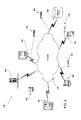
- FIG. 2 A graphical representation of an embodiment 100 of the system of this invention is shown in FIG. 2 and another schematic representation of an embodiment 200 of the system of this invention is shown in FIG. 3 .
- the embodiment 100 of the system of this invention shown in FIG. 2 includes a network monitoring subsystem 110 capable of monitoring a network transmission event at a network location 120 , a central monitoring subsystem (server) 130 , and a number of other network monitoring devices 140 , 160 , 180 , 190 at a number of other network locations 150 , 170 , 185 , 195 .
- server central monitoring subsystem
- both the network monitoring subsystems 110 , 140 , 160 , 180 , 190 and the central monitoring subsystem (server) 130 are based on based on an implementation such as, but not limited to, that shown in FIG. 4 , where the subsystem includes a network interface component 320 , one or more processors 310 , one or more computer readable memories 360 , and at least one other computer readable memory 340 .
- the network interface component 320 , the one or more processors 310 , the one or more computer readable memories 360 , and the one or more computer readable memories 340 are operably connected by means of a interconnection means 325 (such as, but not limited to, a common “bus”).
- a network monitoring subsystem 110 acquires the data from a network transmission event at a first network location such as network location 120 in FIG. 2 (the network location 205 in FIG. 3 can correspond to any network location in FIG. 2 ) by means of the acquisition hardware 215 (the acquisition hardware can be similar, but is not limited to, to that found in network analyzers such as the “J6800A Network Analyzer” of AGILENT TECHNOLOGIES, Inc.).
- the data is analyzed by means of a test instrument application code 220 .
- the test instrument application code 220 provides the means for detecting a predetermined condition in the network transmission event at the network location and obtaining, at the network location 205 , identifying information for the network transmission event.
- the protocol datagram for the protocol utilized in the network transmission provides either the data to be compared against a threshold or to be processed and compared against a threshold in order to determine whether a predetermined condition has occurred.
- the identifying information for the network transmission event is also contained in the protocol datagram. In the embodiment shown in FIG.
- software used for communicating with the central monitoring subsystem 130 (the XML APIs 225 , the communication servlet 230 and the HTTP server 235 provide the software (code) in the embodiment shown) in conjunction with the processor 310 and the network interface 320 constitute the means for providing the identifying information to the central monitoring subsystem 130 .
- the identifying information is received and stored by means of the software used for communicating (such as, in the embodiment shown, the HTTP layer 255 , the XML APIs 260 ) and software for data collection 262 and for data storage 265 .
- the identifying information is provided, from the central monitoring subsystem 130 , to one or more other network monitoring devices at the other network locations (such as network monitoring devices 140 , 160 , 180 , 190 at a number of other network locations 150 , 170 , 185 , 195 in FIG. 2 ) by means of software used for communicating with the network monitoring device 210 (the HTTP layer 255 , the XML APIs 260 in the embodiment shown in FIG.
- the network transmission event corresponding to the identifying information is monitored by means of acquisition hardware 215 and test instrument application code 220 .
- Each of the network monitoring devices, the network monitoring device 110 at the first network location 120 and the other network monitoring device 140 , 160 , 180 , 190 at the other network locations 150 , 170 , 185 , 195 in FIG. 2 provides network transmission event information corresponding to the identifying information to the central monitoring subsystem 130 by means of software used for communicating with the central monitoring subsystem 130 .
- the one or more computer readable memories in each of the network monitoring devices and in the central monitoring subsystem 130 has readable code embodied therein, the computer readable code capable of causing at least one processor in each of the network monitoring devices and in the central monitoring subsystem 130 to monitor a network transmission event at a first network location, detect a predetermined condition in the network transmission event at the first network location, obtain, at the first network location, identifying information for the network transmission event, provide the identifying information to a central monitoring subsystem 130 , provide, from the central monitoring subsystem 130 , the identifying information to one or more network monitoring devices at one or more other network locations, monitor, at the one or more other network location, the network transmission event corresponding to the identifying information, and provide, to the central monitoring subsystem, network transmission event information for the network transmission event corresponding to the identifying information from the first network location and from the one or more other network locations.
- the network monitoring subsystem 110 provides the identifying information to a central monitoring server 130 (location)
- the location of the network monitoring subsystem that provides the identifying information to the central monitoring location is not a limitation of this invention. Any of the other network monitoring devices 140 , 160 , 180 , or 190 could be the network monitoring subsystem (device) that provides the identifying information to the central monitoring server (location).
- a calling telephone 150 i.e., source
- a receiving telephone 185 i.e., receiver
- access a network 105 utilizing VoIP (Voice Over Internet Protocol)
- VoIP Voice Over Internet Protocol
- gateways can be used to connect the phones to the network.
- the VoIP call is routed between the source 150 and the receiver 185 over the network 105 , using Internet Protocol, and through a number of gatekeeper servers such as server 120 and server 170 .
- a signaling protocol (such as SIP or H.323) establishes a transmit and receive channel over the IP network 105 .
- the VoIP data communication utilizes the Real-Time Transport Protocol/User Datagram Protocol/Internet Protocol (RTP/UDP/IP)as the protocol stack.
- RTP/UDP/IP Real-Time Transport Protocol/User Datagram Protocol/Internet Protocol
- FIG. 5 An example of an RTP datagram is shown in FIG. 5 .
- the RTP fields include fields for a sequence number, time stamp, synchronization source identifiers, and contributing source identifiers. (RTP is defined in RFC3550, “RTP: A Transport Protocol for Real-time applications”, July 2003, available at http://www.ietf.org/rfc/rfc3550.txt, which is herein incorporated by reference.)
- an RTP session is defined by a particular pair of destination transport addresses one network address plus a port pair for RTP and RTCP).
- a UDP datagram is shown in FIG. 6 illustrating the port information.
- the timestamp indicates the sampling instant of the first octet in the RTP data packet.
- the sequence number increments by one for each RTP data packet sent, and can be used to detect packet loss.
- the SSRC field uniquely identifies the source.
- the RTP data transport protocol is augmented by a control protocol (RTCP) to allow monitoring of data delivery (allowing scalability to multicast communication), and to provide some control and identification functionality.
- RTCP control protocol
- sources and receivers periodically send RTCP packets to each other (using different ports).
- Each RTCP packet comprises either a sender report or a receiver report followed by a source description (SDES).
- Sender reports (SR) are generated by the RTP sources.
- Receiver report (RR) are generated by the RTP receivers.
- Source description packets, used for session control, include a globally unique identifier, CNAME, and also identify the sender by name, e-mail and phone number. Both sender reports and receiver reports include lost packet and jitter information. The jitter information is obtained from the timestamp.
- a sender report RTCP datagram is shown in FIG. 7 .
- the network monitoring subsystem 110 monitors, at network location 120 , the RTP data packets originated by the phone call (network transmission event) from the calling telephone 150 (i.e., source) to the receiving telephone 185 (i.e., receiver).
- the network monitoring subsystem is a network analyzer such as, but not limited to, a “J6800A Network Analyzer (hardware) and J6844A Telephony Network Analyzer (software)” from AGILENT TECHNOLOGIES, Inc.
- a network analyzer such as, but not limited to, a “J6800A Network Analyzer (hardware) and J6844A Telephony Network Analyzer (software)” from AGILENT TECHNOLOGIES, Inc.
- the network monitoring subsystem 110 extracts and monitors RTCP SR/RR packets between the source 150 and the receiver 185 .
- the network monitoring subsystem 110 extracts RTCP SR/RR packets using conventional methods.
- the RR packet is parsed and jitter and packet loss data are extracted therefrom.
- the SR packet is parsed and data corresponding to a number of packets and octets sent is extracted therefrom. From the SSRC (and, in some embodiments, the source port and destination port from the related RTP/UDP packet), identifying information for the network transmission event (VoIP phone call) is obtained.
- a quality of service (QOS) measure such as, but not limited to, a calculated Mean Opinion Score, may be determined based on the jitter and the packet loss where each is provided a weighing value and thresholds. Preselected thresholds for jitter, packet loss and/or QOS are provided. The extracted data or a quantity derived from the extracted data is compared against a threshold in order to determine whether a predetermined condition has occurred. If a predetermined condition has occurred, the identifying information is provided from network monitoring subsystem 110 to a central monitoring server 130 (location).
- QOS quality of service
- the identifying information is provided to each (or at least one) of the other network monitoring devices 140 , 160 , 180 , 190 at each of the other network locations 150 , 170 , 185 , 195 .
- the network transmission event (phone call) corresponding to the identifying information is monitored, in one embodiment, in the manner described herein above.
- Network transmission event information such as jitter, packet loss and/or QOS, from the first network location 120 and the other network locations 150 , 170 , 185 , 195 , obtained from the network monitoring devices 110 , 140 , 160 , 180 , and 190 , is provided to the central monitoring server (location) 130 .
- a coordinated view of the network transmission corresponding to the network transmission event (phone call) is then obtained at the central monitoring server 130 . From the coordinated view of the network transmission, a location and nature of the root cause of the predetermined condition can be obtained.
- the network monitoring subsystem 110 provides the identifying information to a central monitoring server 130 (location)
- the location of the network monitoring subsystem that provides the identifying information to the central monitoring server is not a limitation of this invention. Any of the other network monitoring devices 140 , 160 , 180 , or 190 could be the network monitoring subsystem (device) that provides the identifying information to the central monitoring server.
- central monitoring location could be implemented in hardware, software or a combination thereof.
- An exemplary embodiment of the central monitoring location (server) is the J6782A Network Troubleshooting Center (NTC) from Agilent Technologies, Inc., a software based system. It should also be noted that this invention is not limited to that embodiment.
- the exemplary network 100 is each simplified for ease of explanation.
- the networks 100 may include more or fewer additional elements such as networks, communication links, proxies, firewalls or other security mechanisms, Internet Service Providers (ISPs), MCUs, gatekeepers, gateways, and other elements.
- ISPs Internet Service Providers
- MCUs Mobility Control Units
- gatekeepers Gatekeepers
- gateways gateways
- the techniques described above may be implemented, for example, in hardware, software, firmware, or any combination thereof.
- the techniques described above may be implemented in one or more computer programs executing on a programmable computer including a processor, a storage medium readable by the processor (including, for example, volatile and non-volatile memory and/or storage elements), at least one input device, and at least one output device.
- Program code may be applied to data entered using the input device to perform the functions described and to generate output information.
- the output information may be applied to one or more output devices.
- Each computer program (code) within the scope of the claims below may be implemented in any programming language, such as assembly language, machine language, a high-level procedural programming language, or an object-oriented programming language.
- the programming language may be a compiled or interpreted programming language.
- Each computer program may be implemented in a computer program product tangibly embodied in a computer-readable storage device for execution by a computer processor. Method steps of the invention may be performed by a computer processor executing a program tangibly embodied on a computer-readable medium to perform functions of the invention by operating on input and generating output.
- Computer-readable or usable media include, for example, a floppy disk, a flexible disk, hard disk, magnetic tape, or any other magnetic medium, a CDROM, any other optical medium, punched cards, paper tape, any other physical medium with patterns of holes, a RAM, a PROM, and EPROM, a FLASH-EPROM, any other memory chip or cartridge, or any other medium from which a computer can read.
Landscapes
- Engineering & Computer Science (AREA)
- Signal Processing (AREA)
- Computer Networks & Wireless Communication (AREA)
- Quality & Reliability (AREA)
- Multimedia (AREA)
- Data Exchanges In Wide-Area Networks (AREA)
Abstract
Description
Claims (14)
Priority Applications (5)
| Application Number | Priority Date | Filing Date | Title |
|---|---|---|---|
| US10/926,191 US7719965B2 (en) | 2004-08-25 | 2004-08-25 | Methods and systems for coordinated monitoring of network transmission events |
| DE102005020088A DE102005020088A1 (en) | 2004-08-25 | 2005-04-29 | Methods and systems for coordinated monitoring of network transmission events |
| GB0512948A GB2417638B (en) | 2004-08-25 | 2005-06-24 | Methods and systems for coordinated monitoring of network transmission events |
| CNB2005100886899A CN100473025C (en) | 2004-08-25 | 2005-08-01 | Method and system for coordinated monitoring of network transmission events |
| JP2005237251A JP2006067582A (en) | 2004-08-25 | 2005-08-18 | Method and system for monitoring coordinated network transmission events |
Applications Claiming Priority (1)
| Application Number | Priority Date | Filing Date | Title |
|---|---|---|---|
| US10/926,191 US7719965B2 (en) | 2004-08-25 | 2004-08-25 | Methods and systems for coordinated monitoring of network transmission events |
Publications (2)
| Publication Number | Publication Date |
|---|---|
| US20060056389A1 US20060056389A1 (en) | 2006-03-16 |
| US7719965B2 true US7719965B2 (en) | 2010-05-18 |
Family
ID=34862268
Family Applications (1)
| Application Number | Title | Priority Date | Filing Date |
|---|---|---|---|
| US10/926,191 Active 2028-12-03 US7719965B2 (en) | 2004-08-25 | 2004-08-25 | Methods and systems for coordinated monitoring of network transmission events |
Country Status (5)
| Country | Link |
|---|---|
| US (1) | US7719965B2 (en) |
| JP (1) | JP2006067582A (en) |
| CN (1) | CN100473025C (en) |
| DE (1) | DE102005020088A1 (en) |
| GB (1) | GB2417638B (en) |
Families Citing this family (30)
| Publication number | Priority date | Publication date | Assignee | Title |
|---|---|---|---|---|
| US20060155824A1 (en) * | 2005-01-11 | 2006-07-13 | Tetsuro Motoyama | Method and system for extracting information from networked devices using the HTTP protocol and precondition information |
| US8098582B2 (en) | 2005-03-31 | 2012-01-17 | At&T Intellectual Property I, L.P. | Methods, systems, and computer program products for implementing bandwidth control services |
| US8024438B2 (en) | 2005-03-31 | 2011-09-20 | At&T Intellectual Property, I, L.P. | Methods, systems, and computer program products for implementing bandwidth management services |
| US8335239B2 (en) | 2005-03-31 | 2012-12-18 | At&T Intellectual Property I, L.P. | Methods, systems, and devices for bandwidth conservation |
| US7975283B2 (en) | 2005-03-31 | 2011-07-05 | At&T Intellectual Property I, L.P. | Presence detection in a bandwidth management system |
| US8306033B2 (en) | 2005-03-31 | 2012-11-06 | At&T Intellectual Property I, L.P. | Methods, systems, and computer program products for providing traffic control services |
| US20060224402A1 (en) * | 2005-04-04 | 2006-10-05 | Bellsouth Intellectual Property Corporation | Devices and methods for monitoring distributed services |
| US7508606B2 (en) * | 2005-07-29 | 2009-03-24 | Flextronics Ap Llc | Method of aligning the upper and lower centering bells of a lens doublet assembly machine |
| US8104054B2 (en) | 2005-09-01 | 2012-01-24 | At&T Intellectual Property I, L.P. | Methods, systems, and devices for bandwidth conservation |
| US8701148B2 (en) | 2005-09-01 | 2014-04-15 | At&T Intellectual Property I, L.P. | Methods, systems, and devices for bandwidth conservation |
| US7573011B2 (en) * | 2005-09-08 | 2009-08-11 | Flextronics Ap, Llc | Zoom module using actuator and lead screw with translating operation |
| US7590505B2 (en) * | 2005-09-08 | 2009-09-15 | Flextronics Ap, Llc | Manufacturable micropositioning system employing sensor target |
| US7531773B2 (en) | 2005-09-08 | 2009-05-12 | Flextronics Ap, Llc | Auto-focus and zoom module having a lead screw with its rotation results in translation of an optics group |
| KR100792374B1 (en) * | 2006-08-24 | 2008-01-08 | 주식회사 이노와이어리스 | Monitoring system and method of trunk gateway |
| US8112128B2 (en) * | 2006-08-31 | 2012-02-07 | Flextronics Ap, Llc | Discreetly positionable camera housing |
| US7580209B2 (en) * | 2006-09-15 | 2009-08-25 | Flextronics Ap, Llc | Auto-focus and zoom module with vibrational actuator and position sensing method |
| WO2008133943A1 (en) * | 2007-04-24 | 2008-11-06 | Flextronics Ap Llc | Small form factor modules using wafer level optics with bottom cavity and flip chip assembly |
| CA2685083A1 (en) * | 2007-04-24 | 2008-11-06 | Harpuneet Singh | Auto focus/zoom modules using wafer level optics |
| CN103424951B (en) * | 2007-05-07 | 2016-12-28 | 南昌欧菲光电技术有限公司 | Camera blade shutter module |
| US8083421B2 (en) * | 2007-05-07 | 2011-12-27 | Flextronics Ap, Llc | AF/zoom shutter with two blades function |
| US7825985B2 (en) * | 2007-07-19 | 2010-11-02 | Flextronics Ap, Llc | Camera module back-focal length adjustment method and ultra compact components packaging |
| US8488046B2 (en) * | 2007-12-27 | 2013-07-16 | Digitaloptics Corporation | Configurable tele wide module |
| US8545114B2 (en) | 2011-03-11 | 2013-10-01 | Digitaloptics Corporation | Auto focus-zoom actuator or camera module contamination reduction feature with integrated protective membrane |
| US8982267B2 (en) | 2011-07-27 | 2015-03-17 | Flextronics Ap, Llc | Camera module with particle trap |
| CN103684818A (en) * | 2012-09-07 | 2014-03-26 | 中兴通讯股份有限公司 | Method and device for detecting failures of network channel |
| US10862781B2 (en) | 2018-11-07 | 2020-12-08 | Saudi Arabian Oil Company | Identifying network issues using an agentless probe and end-point network locations |
| US10924328B2 (en) * | 2018-11-16 | 2021-02-16 | Saudi Arabian Oil Company | Root cause analysis for unified communications performance issues |
| US10944622B2 (en) | 2018-11-16 | 2021-03-09 | Saudi Arabian Oil Company | Root cause analysis for unified communications performance issues |
| US11848839B2 (en) * | 2021-09-30 | 2023-12-19 | Forescout Technologies, Inc. | Entity attribute designation based on logic programming |
| US12368591B2 (en) | 2022-03-09 | 2025-07-22 | Saudi Arabian Oil Company | Blockchain enhanced identity access management system |
Citations (22)
| Publication number | Priority date | Publication date | Assignee | Title |
|---|---|---|---|---|
| JPH0344124A (en) | 1989-07-11 | 1991-02-26 | Nec Corp | Fault decision system |
| US5315580A (en) * | 1990-09-28 | 1994-05-24 | Hewlett-Packard Company | Network monitoring device and system |
| US5365514A (en) * | 1993-03-01 | 1994-11-15 | International Business Machines Corporation | Event driven interface for a system for monitoring and controlling a data communications network |
| US5426741A (en) * | 1991-02-20 | 1995-06-20 | Digital Equipment Corporation | Bus event monitor |
| JPH09247150A (en) | 1996-03-12 | 1997-09-19 | Fujitsu Ltd | Network network monitoring system, central monitoring device and proxy monitoring device used in network network monitoring system |
| WO1998000939A1 (en) | 1996-06-28 | 1998-01-08 | Mci Communications Corporation | System and method for monitoring point identification |
| EP1150212A2 (en) | 2000-04-28 | 2001-10-31 | Microsoft Corporation | System and method for implementing polling agents in a client management tool |
| US20020019870A1 (en) * | 2000-06-29 | 2002-02-14 | International Business Machines Corporation | Proactive on-line diagnostics in a manageable network |
| US6381656B1 (en) * | 1999-03-10 | 2002-04-30 | Applied Microsystems Corporation | Method and apparatus for monitoring input/output (“I/O”) performance in I/O processors |
| US6532554B1 (en) * | 1999-11-29 | 2003-03-11 | Sun Microsystems, Inc. | Network event correlation system using formally specified models of protocol behavior |
| US6577597B1 (en) * | 1999-06-29 | 2003-06-10 | Cisco Technology, Inc. | Dynamic adjustment of network elements using a feedback-based adaptive technique |
| US6594774B1 (en) * | 1999-09-07 | 2003-07-15 | Microsoft Corporation | Method and apparatus for monitoring computer system objects to improve system reliability |
| US20040066753A1 (en) | 2002-10-04 | 2004-04-08 | Grovenburg William Grant | System and method to monitor RTP streams using RTCP SR/RR packet information |
| US6859829B1 (en) * | 1999-02-23 | 2005-02-22 | Microsoft Corp. | Method and mechanism for providing computer programs with computer system events |
| US20050144505A1 (en) * | 2003-11-28 | 2005-06-30 | Fujitsu Limited | Network monitoring program, network monitoring method, and network monitoring apparatus |
| US6931524B2 (en) * | 2001-08-29 | 2005-08-16 | Koninklijke Philips Electronics N.V. | System for bus monitoring using a reconfigurable bus monitor which is adapted to report back to CPU in response to detecting certain selected events |
| US6973034B1 (en) * | 1999-06-29 | 2005-12-06 | Cisco Technology, Inc. | Technique for collecting operating information from network elements, and for controlling network element behavior in a feedback-based, adaptive data network |
| US7016957B2 (en) * | 1998-02-05 | 2006-03-21 | Hitachi, Ltd. | Distributed data processing system and error analysis information saving method appropriate therefor |
| US7017071B2 (en) * | 2000-11-17 | 2006-03-21 | Canon Kabushiki Kaisha | Apparatus for managing a device, program for managing a device, storage medium on which a program for managing a device is stored, and method of managing a device |
| US7035210B2 (en) * | 2001-07-12 | 2006-04-25 | Telefonaktiebolaget Lm Ericsson (Publ) | Media stream delay monitoring for node |
| US7143197B1 (en) * | 1999-11-08 | 2006-11-28 | Agere Systems Inc. | Method and system for monitoring a telecommunications signal transmission link |
| US7349964B2 (en) * | 2000-07-25 | 2008-03-25 | Ricoh Company, Ltd. | Method and system for diagnosing, collecting information and servicing a remote system |
-
2004
- 2004-08-25 US US10/926,191 patent/US7719965B2/en active Active
-
2005
- 2005-04-29 DE DE102005020088A patent/DE102005020088A1/en not_active Withdrawn
- 2005-06-24 GB GB0512948A patent/GB2417638B/en not_active Expired - Fee Related
- 2005-08-01 CN CNB2005100886899A patent/CN100473025C/en not_active Expired - Lifetime
- 2005-08-18 JP JP2005237251A patent/JP2006067582A/en active Pending
Patent Citations (22)
| Publication number | Priority date | Publication date | Assignee | Title |
|---|---|---|---|---|
| JPH0344124A (en) | 1989-07-11 | 1991-02-26 | Nec Corp | Fault decision system |
| US5315580A (en) * | 1990-09-28 | 1994-05-24 | Hewlett-Packard Company | Network monitoring device and system |
| US5426741A (en) * | 1991-02-20 | 1995-06-20 | Digital Equipment Corporation | Bus event monitor |
| US5365514A (en) * | 1993-03-01 | 1994-11-15 | International Business Machines Corporation | Event driven interface for a system for monitoring and controlling a data communications network |
| JPH09247150A (en) | 1996-03-12 | 1997-09-19 | Fujitsu Ltd | Network network monitoring system, central monitoring device and proxy monitoring device used in network network monitoring system |
| WO1998000939A1 (en) | 1996-06-28 | 1998-01-08 | Mci Communications Corporation | System and method for monitoring point identification |
| US7016957B2 (en) * | 1998-02-05 | 2006-03-21 | Hitachi, Ltd. | Distributed data processing system and error analysis information saving method appropriate therefor |
| US6859829B1 (en) * | 1999-02-23 | 2005-02-22 | Microsoft Corp. | Method and mechanism for providing computer programs with computer system events |
| US6381656B1 (en) * | 1999-03-10 | 2002-04-30 | Applied Microsystems Corporation | Method and apparatus for monitoring input/output (“I/O”) performance in I/O processors |
| US6577597B1 (en) * | 1999-06-29 | 2003-06-10 | Cisco Technology, Inc. | Dynamic adjustment of network elements using a feedback-based adaptive technique |
| US6973034B1 (en) * | 1999-06-29 | 2005-12-06 | Cisco Technology, Inc. | Technique for collecting operating information from network elements, and for controlling network element behavior in a feedback-based, adaptive data network |
| US6594774B1 (en) * | 1999-09-07 | 2003-07-15 | Microsoft Corporation | Method and apparatus for monitoring computer system objects to improve system reliability |
| US7143197B1 (en) * | 1999-11-08 | 2006-11-28 | Agere Systems Inc. | Method and system for monitoring a telecommunications signal transmission link |
| US6532554B1 (en) * | 1999-11-29 | 2003-03-11 | Sun Microsystems, Inc. | Network event correlation system using formally specified models of protocol behavior |
| EP1150212A2 (en) | 2000-04-28 | 2001-10-31 | Microsoft Corporation | System and method for implementing polling agents in a client management tool |
| US20020019870A1 (en) * | 2000-06-29 | 2002-02-14 | International Business Machines Corporation | Proactive on-line diagnostics in a manageable network |
| US7349964B2 (en) * | 2000-07-25 | 2008-03-25 | Ricoh Company, Ltd. | Method and system for diagnosing, collecting information and servicing a remote system |
| US7017071B2 (en) * | 2000-11-17 | 2006-03-21 | Canon Kabushiki Kaisha | Apparatus for managing a device, program for managing a device, storage medium on which a program for managing a device is stored, and method of managing a device |
| US7035210B2 (en) * | 2001-07-12 | 2006-04-25 | Telefonaktiebolaget Lm Ericsson (Publ) | Media stream delay monitoring for node |
| US6931524B2 (en) * | 2001-08-29 | 2005-08-16 | Koninklijke Philips Electronics N.V. | System for bus monitoring using a reconfigurable bus monitor which is adapted to report back to CPU in response to detecting certain selected events |
| US20040066753A1 (en) | 2002-10-04 | 2004-04-08 | Grovenburg William Grant | System and method to monitor RTP streams using RTCP SR/RR packet information |
| US20050144505A1 (en) * | 2003-11-28 | 2005-06-30 | Fujitsu Limited | Network monitoring program, network monitoring method, and network monitoring apparatus |
Non-Patent Citations (3)
| Title |
|---|
| "Network Troubleshooting Center-Technical Overview," 5988-8548EN. © Agilent Technologies, Inc. 2003. Printed in U.S.A. Oct. 15, 2003. |
| Hardman, D. "Noise and Voice Quality in VoIP Environments-White Paper," 5988-9345EN. © Agilent Technologies, Inc. 2003. Printed in U.S.A. Apr. 23, 2003. |
| Schulzrinne, H. et al. "RTP: A Transport Protocol for Real-Time Applications." © The Internet Society 2003. Retrieved from www.ietf.org/rfc/rfc3550.txt on Aug. 17, 2004. |
Also Published As
| Publication number | Publication date |
|---|---|
| GB2417638A (en) | 2006-03-01 |
| CN1741483A (en) | 2006-03-01 |
| CN100473025C (en) | 2009-03-25 |
| GB2417638B (en) | 2007-08-22 |
| JP2006067582A (en) | 2006-03-09 |
| DE102005020088A1 (en) | 2006-03-09 |
| GB0512948D0 (en) | 2005-08-03 |
| US20060056389A1 (en) | 2006-03-16 |
Similar Documents
| Publication | Publication Date | Title |
|---|---|---|
| US7719965B2 (en) | Methods and systems for coordinated monitoring of network transmission events | |
| EP2678990B1 (en) | Voip quality measurement enhancements using the internet control message protocol | |
| US7936694B2 (en) | Sniffing-based network monitoring | |
| EP2801173B1 (en) | Determination of a quality induced termination rate of communication sessions | |
| US9602376B2 (en) | Detection of periodic impairments in media streams | |
| US7519006B1 (en) | Method and apparatus for measuring one-way delay at arbitrary points in network | |
| US8867385B2 (en) | Tunneling reports for real-time Internet Protocol media streams | |
| US7496044B1 (en) | Method and apparatus for analyzing a media path for an internet protocol (IP) media session | |
| US20020051464A1 (en) | Quality of transmission across packet-based networks | |
| KR20100120823A (en) | Voip anomaly traffic detection method with flow-level data | |
| US20070286351A1 (en) | Method and System for Adaptive Media Quality Monitoring | |
| US7675948B2 (en) | Performance analysis of a circuit switched mobile telecommunications network | |
| KR100936236B1 (en) | Apparatus and method for monitoring quality of service metric of QoS voice traffic using SPI / RTP | |
| US20040160896A1 (en) | Method and apparatus for adaptive capture of voice over packet (VoP) data | |
| US7733769B1 (en) | Method and apparatus for identifying a media path in a network | |
| WO2011116938A1 (en) | Impairment detection and recording of isochronous media streams | |
| Anderson et al. | SIPFIX: A scheme for distributed SIP monitoring | |
| Kitatsuji et al. | Performance monitoring of VoIP flows for large network operations | |
| Singh et al. | Considerations for Selecting RTP Control Protocol (RTCP) Extended Report (XR) Metrics for the WebRTC Statistics API | |
| Stack | VoIP Overview | |
| Romascanu et al. | Internet Engineering Task Force (IETF) V. Singh Request for Comments: 8451 callstats. io Category: Informational R. Huang | |
| Maritz | A network traffic analysis tool for the prediction of perceived VoIP call quality |
Legal Events
| Date | Code | Title | Description |
|---|---|---|---|
| AS | Assignment |
Owner name: AGILENT TECHNOLOGIES, INC., COLORADO Free format text: ASSIGNMENT OF ASSIGNORS INTEREST;ASSIGNORS:MONK, JOHN M.;BENNETT, TIMOTHY M.;BLOMQUIST, SCOTT A.;REEL/FRAME:015273/0711 Effective date: 20040823 Owner name: AGILENT TECHNOLOGIES, INC.,COLORADO Free format text: ASSIGNMENT OF ASSIGNORS INTEREST;ASSIGNORS:MONK, JOHN M.;BENNETT, TIMOTHY M.;BLOMQUIST, SCOTT A.;REEL/FRAME:015273/0711 Effective date: 20040823 |
|
| STCF | Information on status: patent grant |
Free format text: PATENTED CASE |
|
| AS | Assignment |
Owner name: JDS UNIPHASE CORPORATION,CALIFORNIA Free format text: ASSIGNMENT OF ASSIGNORS INTEREST;ASSIGNOR:AGILENT TECHNOLOGIES, INC.;REEL/FRAME:024433/0138 Effective date: 20100430 Owner name: JDS UNIPHASE CORPORATION, CALIFORNIA Free format text: ASSIGNMENT OF ASSIGNORS INTEREST;ASSIGNOR:AGILENT TECHNOLOGIES, INC.;REEL/FRAME:024433/0138 Effective date: 20100430 |
|
| FPAY | Fee payment |
Year of fee payment: 4 |
|
| AS | Assignment |
Owner name: VIAVI SOLUTIONS INC., CALIFORNIA Free format text: CHANGE OF NAME;ASSIGNOR:JDS UNIPHASE CORPORATION;REEL/FRAME:037057/0627 Effective date: 20150731 |
|
| FEPP | Fee payment procedure |
Free format text: PAYOR NUMBER ASSIGNED (ORIGINAL EVENT CODE: ASPN); ENTITY STATUS OF PATENT OWNER: LARGE ENTITY |
|
| MAFP | Maintenance fee payment |
Free format text: PAYMENT OF MAINTENANCE FEE, 8TH YEAR, LARGE ENTITY (ORIGINAL EVENT CODE: M1552) Year of fee payment: 8 |
|
| AS | Assignment |
Owner name: WELLS FARGO BANK, NATIONAL ASSOCIATION, AS ADMINISTRATIVE AGENT, COLORADO Free format text: SECURITY INTEREST;ASSIGNORS:VIAVI SOLUTIONS INC.;3Z TELECOM, INC.;ACTERNA LLC;AND OTHERS;REEL/FRAME:052729/0321 Effective date: 20200519 |
|
| MAFP | Maintenance fee payment |
Free format text: PAYMENT OF MAINTENANCE FEE, 12TH YEAR, LARGE ENTITY (ORIGINAL EVENT CODE: M1553); ENTITY STATUS OF PATENT OWNER: LARGE ENTITY Year of fee payment: 12 |
|
| AS | Assignment |
Owner name: RPC PHOTONICS, INC., NEW YORK Free format text: TERMINATIONS OF SECURITY INTEREST AT REEL 052729, FRAME 0321;ASSIGNOR:WELLS FARGO BANK, NATIONAL ASSOCIATION, AS ADMINISTRATIVE AGENT;REEL/FRAME:058666/0639 Effective date: 20211229 Owner name: VIAVI SOLUTIONS INC., CALIFORNIA Free format text: TERMINATIONS OF SECURITY INTEREST AT REEL 052729, FRAME 0321;ASSIGNOR:WELLS FARGO BANK, NATIONAL ASSOCIATION, AS ADMINISTRATIVE AGENT;REEL/FRAME:058666/0639 Effective date: 20211229 |
|
| AS | Assignment |
Owner name: WELLS FARGO BANK, NATIONAL ASSOCIATION, AS ADMINISTRATIVE AGENT, CALIFORNIA Free format text: SECURITY AGREEMENT;ASSIGNORS:INERTIAL LABS, INC.;VIAVI SOLUTIONS INC.;VIAVI SOLUTIONS LICENSING LLC;REEL/FRAME:073189/0873 Effective date: 20251016 |
|
| AS | Assignment |
Owner name: WELLS FARGO BANK, NATIONAL ASSOCIATION, AS AGENT, CALIFORNIA Free format text: SECURITY INTEREST;ASSIGNORS:VIAVI SOLUTIONS INC.;VIAVI SOLUTIONS LICENSING LLC;INERTIAL LABS, INC.;REEL/FRAME:073571/0137 Effective date: 20251113 |