US7719829B2 - Anti-vibration cage for data storage device - Google Patents
Anti-vibration cage for data storage device Download PDFInfo
- Publication number
- US7719829B2 US7719829B2 US11/849,309 US84930907A US7719829B2 US 7719829 B2 US7719829 B2 US 7719829B2 US 84930907 A US84930907 A US 84930907A US 7719829 B2 US7719829 B2 US 7719829B2
- Authority
- US
- United States
- Prior art keywords
- pivot hole
- shaft
- securing
- gap
- vibration
- Prior art date
- Legal status (The legal status is an assumption and is not a legal conclusion. Google has not performed a legal analysis and makes no representation as to the accuracy of the status listed.)
- Expired - Fee Related, expires
Links
Images


Classifications
-
- G—PHYSICS
- G06—COMPUTING OR CALCULATING; COUNTING
- G06F—ELECTRIC DIGITAL DATA PROCESSING
- G06F1/00—Details not covered by groups G06F3/00 - G06F13/00 and G06F21/00
- G06F1/16—Constructional details or arrangements
- G06F1/18—Packaging or power distribution
- G06F1/183—Internal mounting support structures, e.g. for printed circuit boards, internal connecting means
- G06F1/187—Mounting of fixed and removable disk drives
-
- G—PHYSICS
- G11—INFORMATION STORAGE
- G11B—INFORMATION STORAGE BASED ON RELATIVE MOVEMENT BETWEEN RECORD CARRIER AND TRANSDUCER
- G11B33/00—Constructional parts, details or accessories not provided for in the other groups of this subclass
- G11B33/12—Disposition of constructional parts in the apparatus, e.g. of power supply, of modules
- G11B33/125—Disposition of constructional parts in the apparatus, e.g. of power supply, of modules the apparatus comprising a plurality of recording/reproducing devices, e.g. modular arrangements, arrays of disc drives
- G11B33/127—Mounting arrangements of constructional parts onto a chassis
Definitions
- the present invention relates to anti-vibration cages for data storage devices, and more particularly to an anti-vibration cage with detachable damping members.
- a plurality of data storage devices is usually provided.
- vibration is generated and may damage the data storage devices.
- damping members are often provided.
- a mounting apparatus for data storage devices includes an exterior cage and an interior case for receiving data storage devices therein.
- the exterior cage includes several damping members rotatably attached to sidewalls thereof.
- Each of the damping members includes a damping portion made of vibration absorbing material, and a shaft inserted through the damping portion along a radial direction.
- An anti-vibration cage for a data storage device includes at least a first securing piece with a first pivot hole defined therein; at least a second securing piece with a second pivot hole defined therein, and at least a rotatable damping member.
- a gap is formed in the second securing piece communicating with the second pivot hole.
- the damping member includes a damping portion configured to dampen vibration for the data storage device and a shaft inserted through the damping portion. Ends of the shaft protrude from ends of the damping portion respectively, to rotatably engage in the first and second pivot holes and are passable through the gap so as to facilitate assembly or disassembly of the dampening member to or from the anti-vibration cage.
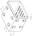
- FIG. 1 is an isometric view of an anti-vibration cage with detachable damping members for data storage devices in accordance with a preferred embodiment of the present invention
- FIG. 2 is a semi-exploded view of FIG. 1 , with two of the damping members detached from the anti-vibration cage;
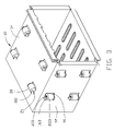
- FIG. 3 is similar to FIG. 2 , showing the two detached damping members being engaged with the disk drive cage.
- an anti-vibration cage 10 for data storage devices includes a plurality of damping members 20 rotatably attached to enclosure panels thereof. Only the damping members 20 attached to adjacent enclosure panels 12 , 14 of the anti-vibration cage 10 are shown in FIG. 1 .
- a plurality of rectangular openings 16 are respectively defined in the panels 12 , 14 .
- a pair of securing pieces 161 , 163 extends perpendicularly outward from each of the panels 12 , 14 from opposite sides of each rectangular opening 16 respectively.
- a width of each of the securing pieces 161 , 163 is less than that of the rectangular opening 16 .
- a first pivot hole 1611 is defined in the securing piece 161
- a second pivot hole 1631 is defined in the securing piece 163 .
- the securing piece 163 defines a gap 1633 communicating with the second pivot hole 1631 therein at a side edge thereof.
- Each damping member 20 includes a cylindrical damping portion 25 , and a shaft 22 inserted through an axial through hole (not shown) of the damping portion 25 .
- the damping portion 25 of the damping member 20 is made from resilient material, which is capable of dampening vibration, such as rubber.
- the shaft 22 is made from rigid material, such as steel.
- a first end 21 and a second end 23 of the shaft 22 protrude out from opposite ends of the damping portion 25 respectively.
- the second end 23 of the shaft 22 includes a first cap 231 , a neck 233 , and a second cap 235 .
- the neck 233 is connected between the first cap 231 and the second cap 235 .
- the diameter of the first or second cap 231 , 235 is greater than the diameter of the second pivot hole 1631 of the securing piece 163 of the anti-vibration cage 10 .
- the diameter of the neck 233 is less than that of the second pivot hole 1631 and a little greater than a natural width of the gap 1633 of the securing piece 163 .
- the diameter of the first end 21 of the shaft 22 is less than that of the first pivot hole 1611 .
- the first end 21 of the shaft 22 of the damping member 20 is inserted into the first pivot hole 1611 of the securing piece 161 . Then the shaft 22 is moved to a perpendicular position with respect to the securing pieces 161 , 163 where the neck 233 of the second end 23 is engaged in the second pivot hole 1631 , from a slanted position with respect to securing pieces 161 , 163 where the neck 233 is engaged to the gap 1633 and resiliently expands the gap 1633 (See FIG. 3 ).
- the gap 1633 of the securing piece 163 returns to its natural width after the neck 233 is fully engaged into the second pivot hole 1631 so that the neck 233 is prevented from accidentally escaping from the second pivot hole 1631 via the gap 1633 . Since the first and second caps 231 , 235 are larger than the second pivot hole 163 , the damping member 20 is reliably and rotatably attached to the securing pieces 161 , 163 .
- the second end 23 of the shaft 22 is moved to expand the gap 1633 so that the neck 233 of the second end 23 of the shaft 22 of the damping member 20 is enabled to disengage from the second pivot hole 163 via the gap 1633 . Then the first end 21 of the shaft 22 is taken out from the first pivot hole 1611 of the securing piece 161 . Thus, the damping member 20 is disassembled from the disk drive bracket 10 .
Landscapes
- Engineering & Computer Science (AREA)
- Theoretical Computer Science (AREA)
- Computer Hardware Design (AREA)
- Power Engineering (AREA)
- Human Computer Interaction (AREA)
- Physics & Mathematics (AREA)
- General Engineering & Computer Science (AREA)
- General Physics & Mathematics (AREA)
- Vibration Prevention Devices (AREA)
- Vibration Dampers (AREA)
Applications Claiming Priority (3)
| Application Number | Priority Date | Filing Date | Title |
|---|---|---|---|
| CNU2007202008075U CN201138570Y (zh) | 2007-08-10 | 2007-08-10 | 数据存储器减震装置 |
| CN200720200807U | 2007-08-10 | ||
| CN200720200807.5 | 2007-08-10 |
Publications (2)
| Publication Number | Publication Date |
|---|---|
| US20090040709A1 US20090040709A1 (en) | 2009-02-12 |
| US7719829B2 true US7719829B2 (en) | 2010-05-18 |
Family
ID=40039252
Family Applications (1)
| Application Number | Title | Priority Date | Filing Date |
|---|---|---|---|
| US11/849,309 Expired - Fee Related US7719829B2 (en) | 2007-08-10 | 2007-09-03 | Anti-vibration cage for data storage device |
Country Status (2)
| Country | Link |
|---|---|
| US (1) | US7719829B2 (zh) |
| CN (1) | CN201138570Y (zh) |
Cited By (9)
| Publication number | Priority date | Publication date | Assignee | Title |
|---|---|---|---|---|
| US20090267276A1 (en) * | 2005-02-18 | 2009-10-29 | Kabushiki Kaisha Kobe Seiko Sho | Vibration Reducing Bracket |
| US20100253186A1 (en) * | 2009-04-03 | 2010-10-07 | Hong Fu Jin Precision Industry (Shenzhen) Co., Ltd. | Electronic device enclosure |
| US20110164379A1 (en) * | 2010-01-05 | 2011-07-07 | Wistron Corporation | Fastener for securing computer storage device |
| US20140139996A1 (en) * | 2012-11-20 | 2014-05-22 | Inventec Corporation | Vibration-absorbing module and case structure thereof |
| US20140285963A1 (en) * | 2011-10-02 | 2014-09-25 | Intal Tech Ltd. | Portable computer vehicle dock |
| US20150378402A1 (en) * | 2013-03-12 | 2015-12-31 | Nec Platforms, Ltd. | Electronic device case structure |
| US9558789B1 (en) | 2015-09-30 | 2017-01-31 | Dot Hill Systems Corporation | Storage device sled and assembly method thereof |
| US9888607B2 (en) | 2015-09-30 | 2018-02-06 | Seagate Technology Llc | Self-biasing storage device sled |
| US10083721B2 (en) | 2015-09-30 | 2018-09-25 | Seagate Technology Llc | Method and apparatus for mitigating induced shock and vibration |
Families Citing this family (3)
| Publication number | Priority date | Publication date | Assignee | Title |
|---|---|---|---|---|
| CN102053678B (zh) * | 2010-12-13 | 2017-03-15 | 王一川 | 电脑机箱减震支脚 |
| TW201301270A (zh) * | 2011-06-20 | 2013-01-01 | Hon Hai Prec Ind Co Ltd | 電子裝置 |
| CN112837711A (zh) * | 2021-02-09 | 2021-05-25 | 拉扎斯网络科技(上海)有限公司 | 装机装置及系统 |
Citations (15)
| Publication number | Priority date | Publication date | Assignee | Title |
|---|---|---|---|---|
| US4705257A (en) * | 1987-03-23 | 1987-11-10 | Digital Equipment Corporation | Shock and vibration isolation mounting |
| US4937806A (en) * | 1988-02-12 | 1990-06-26 | Mdb Systems, Inc. | Shock-isolated portable mass data storage device |
| US5627727A (en) * | 1994-09-02 | 1997-05-06 | Ncr Corporation | Portable computer assembly and method |
| US6008984A (en) * | 1995-08-04 | 1999-12-28 | Havant International Limited | Disk file mounting |
| US6138980A (en) * | 1999-06-24 | 2000-10-31 | Lord Corporation | Pilot mounting |
| US6333848B1 (en) * | 1998-09-21 | 2001-12-25 | Kabushiki Kaisha Toshiba | Storage device with vibration reduction unit |
| US6473299B1 (en) | 1999-09-16 | 2002-10-29 | Intergraph Corporation | Anti-vibration disk drive cage |
| US6505806B1 (en) * | 2000-05-09 | 2003-01-14 | Husky Injection Molding Systems, Ltd. | Dynamic machine mount |
| US20030169565A1 (en) * | 2002-03-07 | 2003-09-11 | Chih-Chong Wang | Non-screwed fastening device |
| US7137767B2 (en) * | 2004-03-24 | 2006-11-21 | Hewlett-Packard Development Company, L.P. | Storage media drive isolation apparatus and methods |
| US7196902B2 (en) * | 2005-01-31 | 2007-03-27 | Hitachi Global Storage Technologies B.V. | Disk drive coupling apparatus for rigidly coupling a disk drive to a chassis of a computer |
| US7307835B1 (en) * | 2006-08-18 | 2007-12-11 | International Business Machines Corporation | Computer module connection |
| US7312999B1 (en) * | 2005-04-29 | 2007-12-25 | Network Appliance, Inc. | High density drive chassis assembly |
| US20080019091A1 (en) * | 2006-07-18 | 2008-01-24 | Hon Hai Precision Industry Co., Ltd. | Mounting apparatus for a data storage device with damping member |
| US7463483B1 (en) * | 2007-06-04 | 2008-12-09 | Inventec Corporation | Bracket structure |
-
2007
- 2007-08-10 CN CNU2007202008075U patent/CN201138570Y/zh not_active Expired - Fee Related
- 2007-09-03 US US11/849,309 patent/US7719829B2/en not_active Expired - Fee Related
Patent Citations (15)
| Publication number | Priority date | Publication date | Assignee | Title |
|---|---|---|---|---|
| US4705257A (en) * | 1987-03-23 | 1987-11-10 | Digital Equipment Corporation | Shock and vibration isolation mounting |
| US4937806A (en) * | 1988-02-12 | 1990-06-26 | Mdb Systems, Inc. | Shock-isolated portable mass data storage device |
| US5627727A (en) * | 1994-09-02 | 1997-05-06 | Ncr Corporation | Portable computer assembly and method |
| US6008984A (en) * | 1995-08-04 | 1999-12-28 | Havant International Limited | Disk file mounting |
| US6333848B1 (en) * | 1998-09-21 | 2001-12-25 | Kabushiki Kaisha Toshiba | Storage device with vibration reduction unit |
| US6138980A (en) * | 1999-06-24 | 2000-10-31 | Lord Corporation | Pilot mounting |
| US6473299B1 (en) | 1999-09-16 | 2002-10-29 | Intergraph Corporation | Anti-vibration disk drive cage |
| US6505806B1 (en) * | 2000-05-09 | 2003-01-14 | Husky Injection Molding Systems, Ltd. | Dynamic machine mount |
| US20030169565A1 (en) * | 2002-03-07 | 2003-09-11 | Chih-Chong Wang | Non-screwed fastening device |
| US7137767B2 (en) * | 2004-03-24 | 2006-11-21 | Hewlett-Packard Development Company, L.P. | Storage media drive isolation apparatus and methods |
| US7196902B2 (en) * | 2005-01-31 | 2007-03-27 | Hitachi Global Storage Technologies B.V. | Disk drive coupling apparatus for rigidly coupling a disk drive to a chassis of a computer |
| US7312999B1 (en) * | 2005-04-29 | 2007-12-25 | Network Appliance, Inc. | High density drive chassis assembly |
| US20080019091A1 (en) * | 2006-07-18 | 2008-01-24 | Hon Hai Precision Industry Co., Ltd. | Mounting apparatus for a data storage device with damping member |
| US7307835B1 (en) * | 2006-08-18 | 2007-12-11 | International Business Machines Corporation | Computer module connection |
| US7463483B1 (en) * | 2007-06-04 | 2008-12-09 | Inventec Corporation | Bracket structure |
Cited By (13)
| Publication number | Priority date | Publication date | Assignee | Title |
|---|---|---|---|---|
| US20090267276A1 (en) * | 2005-02-18 | 2009-10-29 | Kabushiki Kaisha Kobe Seiko Sho | Vibration Reducing Bracket |
| US20100253186A1 (en) * | 2009-04-03 | 2010-10-07 | Hong Fu Jin Precision Industry (Shenzhen) Co., Ltd. | Electronic device enclosure |
| US8070243B2 (en) * | 2009-04-03 | 2011-12-06 | Hong Fu Jin Precision Industry (Shenzhen) Co., Ltd. | Electronic device enclosure |
| US20110164379A1 (en) * | 2010-01-05 | 2011-07-07 | Wistron Corporation | Fastener for securing computer storage device |
| US9557768B2 (en) * | 2011-10-02 | 2017-01-31 | Alexander Vasilevsky | Portable computer vehicle dock |
| US20140285963A1 (en) * | 2011-10-02 | 2014-09-25 | Intal Tech Ltd. | Portable computer vehicle dock |
| US9298218B2 (en) * | 2011-10-02 | 2016-03-29 | Intal Tech Ltd. | Portable computer vehicle dock |
| US20160209872A1 (en) * | 2011-10-02 | 2016-07-21 | Alexander Vasilevsky | Portable computer vehicle dock |
| US20140139996A1 (en) * | 2012-11-20 | 2014-05-22 | Inventec Corporation | Vibration-absorbing module and case structure thereof |
| US20150378402A1 (en) * | 2013-03-12 | 2015-12-31 | Nec Platforms, Ltd. | Electronic device case structure |
| US9558789B1 (en) | 2015-09-30 | 2017-01-31 | Dot Hill Systems Corporation | Storage device sled and assembly method thereof |
| US9888607B2 (en) | 2015-09-30 | 2018-02-06 | Seagate Technology Llc | Self-biasing storage device sled |
| US10083721B2 (en) | 2015-09-30 | 2018-09-25 | Seagate Technology Llc | Method and apparatus for mitigating induced shock and vibration |
Also Published As
| Publication number | Publication date |
|---|---|
| US20090040709A1 (en) | 2009-02-12 |
| CN201138570Y (zh) | 2008-10-22 |
Similar Documents
| Publication | Publication Date | Title |
|---|---|---|
| US7719829B2 (en) | Anti-vibration cage for data storage device | |
| US7616436B2 (en) | Systems and methods for mounting components of an information handling system | |
| US8118377B2 (en) | Computer enclosure | |
| EP2031597B1 (en) | Fixing apparatus for hard disk drive | |
| US8220756B2 (en) | Mounting apparatus for data storage device | |
| US7495907B2 (en) | Mounting apparatus for storage device | |
| EP2031596B1 (en) | Fixing apparatus for hard disk drive | |
| US8004830B2 (en) | Quick-releasing structure for fastening a hard disk, and hard disk carrier and computer system using the same | |
| KR101589276B1 (ko) | 힌지 유니트 및 이를 포함하는 휴대용 컴퓨터 | |
| US8070125B2 (en) | Storage device mounting apparatus | |
| US7656658B2 (en) | Mounting apparatus for data storage device | |
| US9448583B1 (en) | Electronic device and hinge assembly | |
| US8807488B2 (en) | Mounting apparatus for storage device | |
| US9468125B2 (en) | Electronic device | |
| US20090060682A1 (en) | Screw assembly with vibration-absorbing member | |
| US20100103607A1 (en) | Vibration dampening structure for disk drive | |
| US20130033813A1 (en) | Disk drive mounting apparatus | |
| US20060045616A1 (en) | Method and apparatus for mounting a component in an information handling system | |
| US9615479B2 (en) | Slide rail interlocking apparatus and electronic device having the same | |
| US20150285432A1 (en) | Display device holder | |
| US7656655B2 (en) | Mounting apparatus for a data storage device with damping member | |
| US20110103001A1 (en) | Mounting mechanism for hard disk drives | |
| US8070243B2 (en) | Electronic device enclosure | |
| US8556219B2 (en) | Mounting apparatus for data storage device | |
| US20180045223A1 (en) | Fan mount |
Legal Events
| Date | Code | Title | Description |
|---|---|---|---|
| AS | Assignment |
Owner name: HONG FU JIN PRECISION INDUSTRY (SHENZHEN) CO., LTD Free format text: ASSIGNMENT OF ASSIGNORS INTEREST;ASSIGNOR:LI, ZHAN-YANG;REEL/FRAME:019776/0225 Effective date: 20070831 Owner name: HON HAI PRECISION INDUSTRY CO., LTD., TAIWAN Free format text: ASSIGNMENT OF ASSIGNORS INTEREST;ASSIGNOR:LI, ZHAN-YANG;REEL/FRAME:019776/0225 Effective date: 20070831 Owner name: HON HAI PRECISION INDUSTRY CO., LTD.,TAIWAN Free format text: ASSIGNMENT OF ASSIGNORS INTEREST;ASSIGNOR:LI, ZHAN-YANG;REEL/FRAME:019776/0225 Effective date: 20070831 |
|
| REMI | Maintenance fee reminder mailed | ||
| LAPS | Lapse for failure to pay maintenance fees | ||
| STCH | Information on status: patent discontinuation |
Free format text: PATENT EXPIRED DUE TO NONPAYMENT OF MAINTENANCE FEES UNDER 37 CFR 1.362 |
|
| STCH | Information on status: patent discontinuation |
Free format text: PATENT EXPIRED DUE TO NONPAYMENT OF MAINTENANCE FEES UNDER 37 CFR 1.362 |
|
| FP | Lapsed due to failure to pay maintenance fee |
Effective date: 20140518 |