US7719153B2 - Permanent magnet machine and method with reluctance poles and non-identical PM poles for high density operation - Google Patents
Permanent magnet machine and method with reluctance poles and non-identical PM poles for high density operation Download PDFInfo
- Publication number
- US7719153B2 US7719153B2 US11/642,232 US64223206A US7719153B2 US 7719153 B2 US7719153 B2 US 7719153B2 US 64223206 A US64223206 A US 64223206A US 7719153 B2 US7719153 B2 US 7719153B2
- Authority
- US
- United States
- Prior art keywords
- rotor
- flux
- air gap
- portions
- pole
- Prior art date
- Legal status (The legal status is an assumption and is not a legal conclusion. Google has not performed a legal analysis and makes no representation as to the accuracy of the status listed.)
- Expired - Fee Related, expires
Links
- 238000000034 method Methods 0.000 title claims abstract 11
- 230000004907 flux Effects 0.000 claims abstract description 90
- 230000005284 excitation Effects 0.000 claims abstract description 42
- 239000000463 material Substances 0.000 claims abstract description 19
- 230000001939 inductive effect Effects 0.000 claims abstract 2
- 239000003302 ferromagnetic material Substances 0.000 claims description 7
- 230000001360 synchronised effect Effects 0.000 claims description 4
- 230000002401 inhibitory effect Effects 0.000 claims 1
- 238000004804 winding Methods 0.000 claims 1
- 230000004048 modification Effects 0.000 description 8
- 238000012986 modification Methods 0.000 description 8
- 230000005291 magnetic effect Effects 0.000 description 7
- 230000008901 benefit Effects 0.000 description 3
- 238000003475 lamination Methods 0.000 description 3
- 230000000712 assembly Effects 0.000 description 2
- 238000000429 assembly Methods 0.000 description 2
- 230000004888 barrier function Effects 0.000 description 2
- 230000000994 depressogenic effect Effects 0.000 description 2
- 230000006698 induction Effects 0.000 description 2
- 239000000696 magnetic material Substances 0.000 description 2
- RYGMFSIKBFXOCR-UHFFFAOYSA-N Copper Chemical compound [Cu] RYGMFSIKBFXOCR-UHFFFAOYSA-N 0.000 description 1
- 239000004593 Epoxy Substances 0.000 description 1
- XEEYBQQBJWHFJM-UHFFFAOYSA-N Iron Chemical group [Fe] XEEYBQQBJWHFJM-UHFFFAOYSA-N 0.000 description 1
- 239000000853 adhesive Substances 0.000 description 1
- 230000001070 adhesive effect Effects 0.000 description 1
- 229910052802 copper Inorganic materials 0.000 description 1
- 239000010949 copper Substances 0.000 description 1
- 239000000314 lubricant Substances 0.000 description 1
- 239000002184 metal Substances 0.000 description 1
- 229910052751 metal Inorganic materials 0.000 description 1
- 230000009467 reduction Effects 0.000 description 1
- 230000003313 weakening effect Effects 0.000 description 1
Images


Classifications
-
- H—ELECTRICITY
- H02—GENERATION; CONVERSION OR DISTRIBUTION OF ELECTRIC POWER
- H02K—DYNAMO-ELECTRIC MACHINES
- H02K21/00—Synchronous motors having permanent magnets; Synchronous generators having permanent magnets
- H02K21/02—Details
- H02K21/04—Windings on magnets for additional excitation ; Windings and magnets for additional excitation
- H02K21/046—Windings on magnets for additional excitation ; Windings and magnets for additional excitation with rotating permanent magnets and stationary field winding
-
- H—ELECTRICITY
- H02—GENERATION; CONVERSION OR DISTRIBUTION OF ELECTRIC POWER
- H02K—DYNAMO-ELECTRIC MACHINES
- H02K1/00—Details of the magnetic circuit
- H02K1/06—Details of the magnetic circuit characterised by the shape, form or construction
- H02K1/22—Rotating parts of the magnetic circuit
- H02K1/27—Rotor cores with permanent magnets
- H02K1/2706—Inner rotors
- H02K1/272—Inner rotors the magnetisation axis of the magnets being perpendicular to the rotor axis
- H02K1/274—Inner rotors the magnetisation axis of the magnets being perpendicular to the rotor axis the rotor consisting of two or more circumferentially positioned magnets
- H02K1/2753—Inner rotors the magnetisation axis of the magnets being perpendicular to the rotor axis the rotor consisting of two or more circumferentially positioned magnets the rotor consisting of magnets or groups of magnets arranged with alternating polarity
- H02K1/276—Magnets embedded in the magnetic core, e.g. interior permanent magnets [IPM]
- H02K1/2766—Magnets embedded in the magnetic core, e.g. interior permanent magnets [IPM] having a flux concentration effect
Definitions
- the field of the invention is brushless machines, including both AC and DC machines, including both motors and generators, and including induction machines, permanent magnet (PM) machines and switched reluctance machines.
- PM machines have been recognized for having a high power density characteristic.
- a PM rotor does not generate copper losses.
- One drawback of the PM motor for the above-mentioned application is that the air gap flux produced by the PM rotor is limited, and therefore, a sophisticated approach is required for high speed, field weakening operation.
- Another constraint is that inductance is low, which means that current ripple must be controlled.
- a PM electric machine has the property of high efficiency and high power density, however, the air gap flux density of a PM machine is limited by the PM material, which is normally about 0.8 Teslas and below.
- a PM machine cannot operate at an air gap flux density as high as that of a switched reluctance machine.
- a sophisticated power electronics inverter is required.
- Rosenberg et al. U.S. Pat. No. 3,411,027, illustrates a permanent magnet (PM) machine with field excitation. There is no intent to shield the flux path for the field induced flux to prevent flux leakage. Therefore, significant flux leakage would occur resulting in a reduction of power density. In addition, Rosenberg et al. does not teach any additional reluctance poles or reluctance flux paths for producing reluctance torque in such a PM motor.
- PM permanent magnet
- the reluctance torque is produced by the difference between the d-axis inductance, L d , and the q-axis inductance, L q .
- L d the d-axis inductance
- L q the q-axis inductance
- Tarima also discloses symmetrical concavities per pole formed on the air gap face of the magnetic pole pieces of the rotor iron core. These are provided for the purpose of reducing core losses otherwise inherent in the design.
- the present invention is intended to improve reluctance torque and power density in a PM machine, while still providing a compact configuration.
- This invention provides a high density PM machine in which reluctance poles are added to permanent magnets (PM's) in a machine rotor to allow enhanced field control.
- the PM pole portions of one polarity provide enlarged flux paths in relation to flux paths for pole portions of an opposite polarity, with the enlarged flux paths communicating with a core of the rotor so as to increase torque produced by the electric machine.
- the reluctance poles can be provided with asymmetric pole faces.
- DC excitation is provided by asymmetric PMs disposed at the ends of the rotor making it unnecessary to use the stationary DC excitation coil assemblies.
- the PM elements rotate with the rotor.
- FIG. 1 is a longitudinal section view of a brushless PM machine with reluctance poles
- FIG. 2 is a longitudinal section view of a second embodiment of a brushless PM machine with reluctance poles
- FIG. 2 a is a transverse sectional view of a rotor assembly seen in FIG. 2 ;
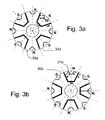
- FIGS. 3 a and 3 b are transverse sectional views of a rotor assembly seen in FIG. 3 ;
- FIG. 4 is a longitudinal section view of a fourth embodiment of a brushless PM machine with reluctance poles w without field excitation coils;
- FIG. 5 shows a modification to the rotor assembly in FIGS. 1-4 ;
- FIGS. 6 a and 6 b are schematic views of one alternative for utilization of excitation coils that can be used in the present invention.
- FIG. 13 shows a modification to the rotor assembly to improve performance while maintaining a uniform air gap.
- the rotor 12 is an assembly that has a hub 12 a with a plurality of laminations 12 b of ferromagnetic material stacked on the hub, keyed to the hub at location 12 c and clamped by non-magnetic metal end pieces 12 d as further described in U.S. Pat. No. 6,972,504, cited above.
- the stacked laminations reduce the occurrence of eddy currents resulting from the flux which travels through in an axial direction through the rotor assembly 12 .
- FIG. 5 shows a modification of the rotor 12 to provide a second set of PM elements 17 a set deeper into the rotor 12 and parallel to the first set of PM elements 17 .
- the spaces between the sets of PM elements 17 , 17 a become N polarity reluctance flux paths 19 for AC flux entering and leaving the rotor through a q-axis N pole.
- the d-axis reluctance flux paths are superimposed on the PM N polarity poles.
- the PM poles are non-identical with S pole portions having enlarged flux paths in relation to flux paths for the N pole portions, the enlarged flux paths communicating with a core 12 a of the rotor 12 so as to increase torque produced by the electric machine.
- the PM material 14 together with the excitation current going through the excitation coils 23 and 24 produces the north (N) and south (S) poles on the exterior of rotor 12 ( FIG. 1 a ) that faces the stator 11 and the radial air gap 20 ( FIG. 1 ).
- This rotor flux in the radial air gap 20 can be either enhanced or weakened according to the polarity of the DC excitation in the excitation assemblies 23 , 24 .
- the radial air gap 20 receives the rotor flux from the rotor 12 , which interacts with the primary flux induced by the coils in the stator 11 to produce a torque.
- FIG. 8 shows a modified rotor 12 ′ in which the d-axis reluctance pole faces 18 a facing the primary air gap 20 each have a groove of varying depth formed in the pole face 18 a , and this groove is asymmetrical in shape and in position and this results in the pole face 18 a being asymmetrical in shape in relation to a radial axis of symmetry 18 b from an axis of rotation 15 b for the rotor 12 ′ to cause a thickness of the primary air gap 20 to vary across the PM and d-axis reluctance pole faces 18 a .
- This increases the air gap asymmetrically across the d-axis pole faces 18 a . This further enhances the forward rotation torque but will reduce the backward rotation torque.
- the difference between the forward and backward torque difference can be controlled through design.
- FIG. 9 shows a modification of the rotor in which the PM pole faces 19 b facing the primary air gap are depressed relative to the pole faces 19 a for the reluctance poles 19 causing a thickness of the primary air gap to vary across the PM pole faces and the reluctance pole faces.
- FIG. 10 shows a modified rotor 12 ′′′ in which the d-axis reluctance pole faces 19 e facing the primary air gap 20 project further into the primary air gap 20 and the pole faces 19 f for the q-axis reluctance poles are recessed relative to the d-axis reluctance pole faces 19 e causing a thickness of the primary air gap to vary across the reluctance pole faces.
- FIG. 10 also shows PM elements 17 b defining the q-axis reluctance poles as being disposed along radiuses parallel to side pieces 17 for the d-axis poles to provide q-axis poles of different sized flux conduction regions than for the d-axis reluctance poles.
- FIG. 13 shows a modification to FIG. 11 in which a thin bridge 19 h is provided over the q-axis poles faces 19 f of FIG. 11 . This reduces the rotor surface variation for noise and hydraulic friction reasons.
Landscapes
- Engineering & Computer Science (AREA)
- Power Engineering (AREA)
- Synchronous Machinery (AREA)
Abstract
Description
Claims (16)
Priority Applications (1)
| Application Number | Priority Date | Filing Date | Title |
|---|---|---|---|
| US11/642,232 US7719153B2 (en) | 2005-12-21 | 2006-12-20 | Permanent magnet machine and method with reluctance poles and non-identical PM poles for high density operation |
Applications Claiming Priority (3)
| Application Number | Priority Date | Filing Date | Title |
|---|---|---|---|
| US75269505P | 2005-12-21 | 2005-12-21 | |
| US80696806P | 2006-07-11 | 2006-07-11 | |
| US11/642,232 US7719153B2 (en) | 2005-12-21 | 2006-12-20 | Permanent magnet machine and method with reluctance poles and non-identical PM poles for high density operation |
Publications (2)
| Publication Number | Publication Date |
|---|---|
| US20070145850A1 US20070145850A1 (en) | 2007-06-28 |
| US7719153B2 true US7719153B2 (en) | 2010-05-18 |
Family
ID=38192804
Family Applications (1)
| Application Number | Title | Priority Date | Filing Date |
|---|---|---|---|
| US11/642,232 Expired - Fee Related US7719153B2 (en) | 2005-12-21 | 2006-12-20 | Permanent magnet machine and method with reluctance poles and non-identical PM poles for high density operation |
Country Status (1)
| Country | Link |
|---|---|
| US (1) | US7719153B2 (en) |
Cited By (11)
| Publication number | Priority date | Publication date | Assignee | Title |
|---|---|---|---|---|
| US20090295249A1 (en) * | 2008-06-02 | 2009-12-03 | Denso Corporation | Hybrid-type synchronous machine |
| US20110169364A1 (en) * | 2010-01-14 | 2011-07-14 | Kabushiki Kaisha Yaskawa Denki | Rotor for use in ipm rotating electric machine, and ipm rotating electric machine provided with the rotor |
| US20110285238A1 (en) * | 2010-05-20 | 2011-11-24 | Denso Corporation | Double-stator motor |
| US20110291515A1 (en) * | 2010-05-31 | 2011-12-01 | Yue Li | Brushless motor |
| CN103066783A (en) * | 2011-10-21 | 2013-04-24 | 株式会社电装 | Double-stator motor |
| US8760105B2 (en) | 2010-11-30 | 2014-06-24 | Ut-Battelle, Llc | Electric machine and current source inverter drive system |
| US20150171678A1 (en) * | 2012-08-29 | 2015-06-18 | Kabushiki Kaisha Yaskawa Denki | Rotary electric machine and rotor |
| US20150270752A1 (en) * | 2013-01-24 | 2015-09-24 | Mitsubishi Electric Corporation | Permanent-magnet-type rotating electric mechanism |
| WO2016115722A1 (en) * | 2015-01-23 | 2016-07-28 | 浙江迈雷科技有限公司 | Permanent magnet synchronous motor |
| US10715017B2 (en) * | 2017-06-02 | 2020-07-14 | Hamilton Sundstrand Corporation | Hybrid synchronous machines |
| US11509175B1 (en) | 2022-04-06 | 2022-11-22 | John Sheung-Chun Hsu | Homopolar multi-core energy conversion device |
Families Citing this family (23)
| Publication number | Priority date | Publication date | Assignee | Title |
|---|---|---|---|---|
| MY148155A (en) * | 2005-10-24 | 2013-03-15 | Panasonic Corp | Capacitor motor and process for producing the same |
| US7719153B2 (en) * | 2005-12-21 | 2010-05-18 | Ut-Battelle, Llc | Permanent magnet machine and method with reluctance poles and non-identical PM poles for high density operation |
| JP4727467B2 (en) * | 2006-03-17 | 2011-07-20 | 日本電産サンキョー株式会社 | motor |
| JP4404223B2 (en) | 2007-03-20 | 2010-01-27 | 株式会社安川電機 | Electromagnetic steel sheet forming body, electromagnetic steel sheet laminate, permanent magnet type synchronous rotating electric machine equipped with the same, permanent magnet type synchronous rotating electric machine, vehicle using the rotating electric machine, elevator, fluid machine, processing machine |
| US7791236B2 (en) | 2007-08-16 | 2010-09-07 | Ford Global Technologies, Llc | Permanent magnet machine |
| JP4492681B2 (en) * | 2007-11-16 | 2010-06-30 | 株式会社デンソー | Synchronous machine |
| US8072113B2 (en) * | 2008-07-22 | 2011-12-06 | Pratt & Whitney Canada Corp. | Inductance augmenter for an electric machine |
| US7902710B2 (en) * | 2008-10-01 | 2011-03-08 | Caterpillar Inc. | Electric machine |
| CN102405583B (en) * | 2009-02-24 | 2014-05-14 | 有限公司日库技术研究所 | Variable magnetic flux rotating electric machine system |
| US20110101817A1 (en) * | 2009-11-05 | 2011-05-05 | Gm Global Technology Operations, Inc. | Variable geometry electric machine |
| JP5708181B2 (en) * | 2010-05-12 | 2015-04-30 | 株式会社デンソー | Rotating electrical machine rotor |
| JP2012080713A (en) * | 2010-10-05 | 2012-04-19 | Hitachi Ltd | Permanent magnet-type rotary electric machine and compressor using the same |
| CN103683768B (en) * | 2012-09-06 | 2017-12-12 | 德昌电机(深圳)有限公司 | Transverse flux permanent magnetic motor |
| US9112386B2 (en) * | 2013-01-15 | 2015-08-18 | Roopnarine | Electric motor with improved flux path and power density |
| JP6451990B2 (en) * | 2015-04-02 | 2019-01-16 | 株式会社デンソー | Rotating electric machine |
| US10491066B2 (en) * | 2015-06-16 | 2019-11-26 | Danfoss Editron Oy | Method and arrangement for adjusting the magnetization of a permanent magnet machine |
| WO2017036549A1 (en) * | 2015-09-04 | 2017-03-09 | Pierburg Pump Technology Gmbh | Automotive auxiliary device with electric drive motor |
| DE102019117364A1 (en) * | 2019-06-27 | 2020-12-31 | Valeo Siemens Eautomotive Germany Gmbh | Rotor for an electric machine, electric machine for a vehicle and a vehicle |
| JP7131521B2 (en) * | 2019-10-02 | 2022-09-06 | トヨタ自動車株式会社 | Rotating electric machine and method for controlling the rotating electric machine |
| WO2021106153A1 (en) * | 2019-11-28 | 2021-06-03 | 三菱電機株式会社 | Rotary electric machine |
| JP2021168536A (en) * | 2020-04-09 | 2021-10-21 | 大銀微系統股▲分▼有限公司Hiwin Mikrosystem Corp. | Rotor structure of permanent magnet motor |
| JP7478104B2 (en) * | 2021-01-08 | 2024-05-02 | 株式会社アイシン | Rotor core |
| CN114567133A (en) * | 2022-04-02 | 2022-05-31 | 山东理工大学 | Production method of asymmetric magnetic pole permanent magnet driving motor rotor |
Citations (13)
| Publication number | Priority date | Publication date | Assignee | Title |
|---|---|---|---|---|
| US3411027A (en) | 1965-07-15 | 1968-11-12 | Siemens Ag | Permanent magnet excited electric machine |
| JP2000288835A (en) * | 1999-03-31 | 2000-10-17 | Amada Co Ltd | Tapping device for plate material working machine |
| US6147428A (en) * | 1997-04-14 | 2000-11-14 | Sanyo Electric Co., Ltd. | Rotor of electric motor |
| US6177745B1 (en) * | 1997-09-26 | 2001-01-23 | Fujitsu General Limited | Permanent magnet rotor type electric motor |
| US6441525B1 (en) | 2000-09-28 | 2002-08-27 | Hitachi, Ltd. | Permanent magnet rotating electric machine |
| US20040007930A1 (en) * | 2002-04-15 | 2004-01-15 | Denso Corporation | Permanent-magnet rotor for an inner rotor type electric rotary machine and magnet-saving type rotor for a synchronous motor |
| US20040232794A1 (en) * | 2003-05-22 | 2004-11-25 | Hsu John S. | Method and radial gap machine for high strength undiffused brushless operation |
| US20050200223A1 (en) | 2004-03-10 | 2005-09-15 | Hitachi, Ltd. | Permanent magnet rotating electric machine and electric car using the same |
| US6967424B2 (en) * | 2003-02-18 | 2005-11-22 | Minebea Co., Ltd. | Rotor assembly and stator assembly for an electrical machine |
| US6972504B1 (en) | 2004-05-18 | 2005-12-06 | Ut-Battelle Llc | Permanent magnet machine and method with reluctance poles for high strength undiffused brushless operation |
| US6989619B2 (en) * | 2003-05-22 | 2006-01-24 | Ut-Battelle Llc | Rotor apparatus for high strength undiffused brushless electric machine |
| US20070145850A1 (en) * | 2005-12-21 | 2007-06-28 | Hsu John S | Permanent magnet machine and method with reluctance poles and non-identical PM poles for high density operation |
| US7518278B2 (en) * | 2004-05-18 | 2009-04-14 | Ut-Battelle, Llc | High strength undiffused brushless machine and method |
-
2006
- 2006-12-20 US US11/642,232 patent/US7719153B2/en not_active Expired - Fee Related
Patent Citations (14)
| Publication number | Priority date | Publication date | Assignee | Title |
|---|---|---|---|---|
| US3411027A (en) | 1965-07-15 | 1968-11-12 | Siemens Ag | Permanent magnet excited electric machine |
| US6147428A (en) * | 1997-04-14 | 2000-11-14 | Sanyo Electric Co., Ltd. | Rotor of electric motor |
| US6177745B1 (en) * | 1997-09-26 | 2001-01-23 | Fujitsu General Limited | Permanent magnet rotor type electric motor |
| JP2000288835A (en) * | 1999-03-31 | 2000-10-17 | Amada Co Ltd | Tapping device for plate material working machine |
| US6441525B1 (en) | 2000-09-28 | 2002-08-27 | Hitachi, Ltd. | Permanent magnet rotating electric machine |
| US20040007930A1 (en) * | 2002-04-15 | 2004-01-15 | Denso Corporation | Permanent-magnet rotor for an inner rotor type electric rotary machine and magnet-saving type rotor for a synchronous motor |
| US6967424B2 (en) * | 2003-02-18 | 2005-11-22 | Minebea Co., Ltd. | Rotor assembly and stator assembly for an electrical machine |
| US20040232794A1 (en) * | 2003-05-22 | 2004-11-25 | Hsu John S. | Method and radial gap machine for high strength undiffused brushless operation |
| US6989619B2 (en) * | 2003-05-22 | 2006-01-24 | Ut-Battelle Llc | Rotor apparatus for high strength undiffused brushless electric machine |
| US7129611B2 (en) * | 2003-05-22 | 2006-10-31 | Ut-Battelle Llc | Method and radial gap machine for high strength undiffused brushless operation |
| US20050200223A1 (en) | 2004-03-10 | 2005-09-15 | Hitachi, Ltd. | Permanent magnet rotating electric machine and electric car using the same |
| US6972504B1 (en) | 2004-05-18 | 2005-12-06 | Ut-Battelle Llc | Permanent magnet machine and method with reluctance poles for high strength undiffused brushless operation |
| US7518278B2 (en) * | 2004-05-18 | 2009-04-14 | Ut-Battelle, Llc | High strength undiffused brushless machine and method |
| US20070145850A1 (en) * | 2005-12-21 | 2007-06-28 | Hsu John S | Permanent magnet machine and method with reluctance poles and non-identical PM poles for high density operation |
Non-Patent Citations (1)
| Title |
|---|
| Koichiro Muta, Makota Yamazaki and Junji Tokieda, Toyota Motor Corp., "Development of New-Generation Hybrid System THS II-Drastic Improvement of Power Performance and Fuel Economy", No. 2004-01-0064, ISBN 0-7680-1319-A, Copyright 2004 SAE International. |
Cited By (19)
| Publication number | Priority date | Publication date | Assignee | Title |
|---|---|---|---|---|
| US8018111B2 (en) * | 2008-06-02 | 2011-09-13 | Denso Corporation | Hybrid-type synchronous machine |
| US20090295249A1 (en) * | 2008-06-02 | 2009-12-03 | Denso Corporation | Hybrid-type synchronous machine |
| US20110169364A1 (en) * | 2010-01-14 | 2011-07-14 | Kabushiki Kaisha Yaskawa Denki | Rotor for use in ipm rotating electric machine, and ipm rotating electric machine provided with the rotor |
| US8319387B2 (en) * | 2010-01-14 | 2012-11-27 | Kabushiki Kaisha Yaskawa Denki | Rotor for use in IPM rotating electric machine, and IPM rotating electric machine provided with the rotor |
| US8427023B2 (en) * | 2010-01-14 | 2013-04-23 | Kabushiki Kaisha Yaskawa Denki | Rotor for use in IPM rotating electric machine, and IPM rotating electric machine provided with the rotor |
| US8860274B2 (en) * | 2010-05-20 | 2014-10-14 | Denso Corporation | Motor provided with two stators arranged radially inside and outside rotor |
| US20110285238A1 (en) * | 2010-05-20 | 2011-11-24 | Denso Corporation | Double-stator motor |
| US20110291515A1 (en) * | 2010-05-31 | 2011-12-01 | Yue Li | Brushless motor |
| US8866359B2 (en) * | 2010-05-31 | 2014-10-21 | Johnson Electric S.A. | Brushless motor having V-shaped permanent magnets |
| US8760105B2 (en) | 2010-11-30 | 2014-06-24 | Ut-Battelle, Llc | Electric machine and current source inverter drive system |
| CN103066783A (en) * | 2011-10-21 | 2013-04-24 | 株式会社电装 | Double-stator motor |
| CN103066783B (en) * | 2011-10-21 | 2015-07-08 | 株式会社电装 | Double-stator motor |
| US20150171678A1 (en) * | 2012-08-29 | 2015-06-18 | Kabushiki Kaisha Yaskawa Denki | Rotary electric machine and rotor |
| US9564780B2 (en) * | 2012-08-29 | 2017-02-07 | Kabushiki Kaisha Yaskawa Denki | Rotary electric machine and rotor |
| US20150270752A1 (en) * | 2013-01-24 | 2015-09-24 | Mitsubishi Electric Corporation | Permanent-magnet-type rotating electric mechanism |
| US9716411B2 (en) * | 2013-01-24 | 2017-07-25 | Mitsubishi Electric Corporation | Permanent-magnet-type rotating electric mechanism |
| WO2016115722A1 (en) * | 2015-01-23 | 2016-07-28 | 浙江迈雷科技有限公司 | Permanent magnet synchronous motor |
| US10715017B2 (en) * | 2017-06-02 | 2020-07-14 | Hamilton Sundstrand Corporation | Hybrid synchronous machines |
| US11509175B1 (en) | 2022-04-06 | 2022-11-22 | John Sheung-Chun Hsu | Homopolar multi-core energy conversion device |
Also Published As
| Publication number | Publication date |
|---|---|
| US20070145850A1 (en) | 2007-06-28 |
Similar Documents
| Publication | Publication Date | Title |
|---|---|---|
| US7719153B2 (en) | Permanent magnet machine and method with reluctance poles and non-identical PM poles for high density operation | |
| US8294321B2 (en) | Brushless machine having ferromagnetic side plates and side magnets | |
| US6972504B1 (en) | Permanent magnet machine and method with reluctance poles for high strength undiffused brushless operation | |
| US8018111B2 (en) | Hybrid-type synchronous machine | |
| US9252634B2 (en) | Synchronous motor | |
| EP1624555A2 (en) | Axial-gap dynamo-electric machine | |
| US7902700B1 (en) | Low harmonic loss brushless motor | |
| KR100615878B1 (en) | IPM motors, motor vehicles, electric cars and trams | |
| US20130187504A1 (en) | Dynamo-electric machine | |
| US10749385B2 (en) | Dual magnetic phase material rings for AC electric machines | |
| US20130134805A1 (en) | Switched reluctance motor | |
| US20130069453A1 (en) | Mechanically commutated switched reluctance motor | |
| JP6668844B2 (en) | Rotating electric machine | |
| US7129611B2 (en) | Method and radial gap machine for high strength undiffused brushless operation | |
| US20130214623A1 (en) | Switched reluctance motor | |
| KR20220044429A (en) | Electric motor having stacked different rotor segments and method for designing the same | |
| CN110994839A (en) | Electric motor rotor and alternating-pole electric motor | |
| US7405504B2 (en) | Rotor for rotary electric machine | |
| US6989619B2 (en) | Rotor apparatus for high strength undiffused brushless electric machine | |
| WO2020194390A1 (en) | Rotating electric machine | |
| JP5805046B2 (en) | Vehicle motor and vehicle generator | |
| US11349358B2 (en) | Apparatus and method for an interior permanent magnet with rotor hybridization | |
| JP2002186244A (en) | Permanent magnet linear motor | |
| US6211596B1 (en) | Claw-pole machine | |
| US6573634B2 (en) | Method and machine for high strength undiffused brushless operation |
Legal Events
| Date | Code | Title | Description |
|---|---|---|---|
| AS | Assignment |
Owner name: U.S. DEPARTMENT OF ENERGY,DISTRICT OF COLUMBIA Free format text: CONFIRMATORY LICENSE;ASSIGNOR:UT-BATTELEE, LLC;REEL/FRAME:019294/0508 Effective date: 20070411 Owner name: U.S. DEPARTMENT OF ENERGY, DISTRICT OF COLUMBIA Free format text: CONFIRMATORY LICENSE;ASSIGNOR:UT-BATTELEE, LLC;REEL/FRAME:019294/0508 Effective date: 20070411 |
|
| AS | Assignment |
Owner name: UT-BATTELLE, LLC,TENNESSEE Free format text: ASSIGNMENT OF ASSIGNORS INTEREST;ASSIGNOR:HSU, JOHN S.;REEL/FRAME:024099/0799 Effective date: 20100318 |
|
| FEPP | Fee payment procedure |
Free format text: PAYOR NUMBER ASSIGNED (ORIGINAL EVENT CODE: ASPN); ENTITY STATUS OF PATENT OWNER: SMALL ENTITY |
|
| FPAY | Fee payment |
Year of fee payment: 4 |
|
| FEPP | Fee payment procedure |
Free format text: MAINTENANCE FEE REMINDER MAILED (ORIGINAL EVENT CODE: REM.) |
|
| LAPS | Lapse for failure to pay maintenance fees |
Free format text: PATENT EXPIRED FOR FAILURE TO PAY MAINTENANCE FEES (ORIGINAL EVENT CODE: EXP.) |
|
| STCH | Information on status: patent discontinuation |
Free format text: PATENT EXPIRED DUE TO NONPAYMENT OF MAINTENANCE FEES UNDER 37 CFR 1.362 |
|
| FP | Lapsed due to failure to pay maintenance fee |
Effective date: 20180518 |